Halma SENSITRON GALILEO 32 User manual

GALILEO 32
SENSITRON
A Halma Company
GALILEO 32
Manuale/Manual
MT2276E
SENSITRON S.R.L. - All rights reserved - www. sensitron.it
Gas contro panel
for addressable gas detectors
Manuale / Manual
MT2276E REV2 18/05/2018©
Sensitron S.r.l., Viale della Repubblica 48, Cornaredo (MI)
TEL. +390293548155 FAX. +390293548089

SENSITRON
A Halma Company
MT2276E
GALILEO 32
Manuale/Manual
P. 2/14
EN
This manual must be carefully read by all persons who have or will have the responsbility for installing, using or servicing this product. Like any
equipment, this product will perform as designed only if installed, used and serviced in accordance with the manufacturer’s instructions. Otherwise, it
could fail to perform as designed and persons who rely on this product for their safety could suer severe personal injury or death.The warranties made
by Sensitron s.r.l. with respect to this product are voided if the product is not installed, used and serviced in accordance with the instructions in
this user guide. Please protect yourself and others by following them. We recommend our customers to write or call regarding this equipment prior to use
or for any additional information relative to use or repair.
EN
P. 3 1. Introduction
P. 5 2. Installation
P. 10 3. System power up and operation
P. 16 4. User levels
P. 17 5. Menu’s details
P. 27 6. PC configuration software

SENSITRON
A Halma Company
MT2276E
GALILEO 32
Manual (EN)
P. 3/14
1. Introduction The present manual explains the procedures for installing, operating and pro-
gramming, as well as some aspects related to the commissioning and mainte-
nance for the control unit Galileo 32.
. DETECTION CONTROL PANEL CHARACTERISTICS
The GALILEO 32 is an advanced multifunction gas detection control panel de-
signed to control and monitor up to 32 SMART 3G detectors connected on a
closed RS 485 serial loop.
Always keeping the main focus on security, the GALILEO 32 control panel has
been developed according to the European standards on functional safety, the
SIL (Safety Integrity Level) requirements (European Standard EN 50402). Re-
dundancy has been implemented in every module being part of the system and
with the correct installation the system comply with the functional safety require-
ments up to SIL 3. On the GALILEO 32 front plate, an high brightness display pro-
vides an ongoing reading of the concentration being measured and, in case of
an alarm, the alarm threshold attained and the respective channel.
The unit comes into a metal cabinet complete with 24Vdc, 5A power supply and
oers the possibility to allocate 2 back-up batteries max. 12V 7 Ah.
An RS232C serial port for connection to a Personal Computer is available, which
permits the remote programming of the control panel with a substantial reduc-
tion in time.
. SYSTEM CONFIGURATION
Figure 1.2
System block diagram

SENSITRON
A Halma Company
MT2276E
GALILEO 32
Manual (EN)
P. 4/14
. TECHNICAL SPECIFICATIONS
Housing Metal cabinet 430 x 405 x 140 mm.
Inputs Max. 32 detectors type SMART “S” on 1 x RS485 closed bus
Outputs 8 relay board mounted in the control panel
Relay contact rating 16 A 250 Vac
Serial ports 1 x RS485 and 1 x RS232
Power Supply 230V AC +/- 10% 50Hz
Power consumption Max 10 VA
Backup battery 2 x 12V 7 Ah max
Display LCD backlight 128x128 points
Visual indications LED 8 double LED on the front panel
Temperature Operational 0-55°C
Storage -20 / +70 C°
Relative humidity Operational 15-85%
Storage 5-85%
(non condensing)

SENSITRON
A Halma Company
MT2276E
GALILEO 32
Manual (EN)
P. 5/14
2. Installation . CONTROL UNIT
Installation cabinet: IP20 minimum.
Devices installed in zone that have been classified and connected to control unit
shall be protected with one of the types of protection listed in EN 60079-0, corre-
sponding to their own category.
Analogue 4-20 mA detectors to be connected shall comply with the following in-
terface specification:
Signals < 3 mA will be interpreted as fault low.
Signals between 3 mA and 4 mA will be indicated as negative signal.
Signals between 20 mA and 21 mA will be indicated as signal above the
measuring range.
Signals > 21 mA will be interpreted as fault high.
Digital RS 485 detectors to be connected shall comply with the high security
data transmission protocol SIL3.
Have the control unit mounted by using the three mounting holes on the back
part of the cabinet.
Connect the three core mains supply cable to the power supply terminals (1.5
mm2per core minimum) and have it secured with the appropriate cable grip.
Connect the Power supply and the RS485 line for the detectors to the terminal
block before powering up the control panel.
After powering up the control panel, connect the red and black power supply ca-
bles fitted with Faston connectors to the 2 x sealed lead acid batteries (12 Vdc / 7
Ah max.). The battery should be carefully fitted inside the space at the left side of
the cabinet.
Figure 2.1
a) Control panel cabinet

SENSITRON
A Halma Company
MT2276E
GALILEO 32
Manual (EN)
P. 6/14
. GAS DETECTORS
GALILEO 32 gas control panel can be connected to Sensitron’s SMART “S” de-
tector version.
Detectors are to be duly installed according to the gas to be detected and in ful-
filment of all EU or national rules in force. Before installing the gas detectors, we
recommend to strictly follow what stated in the detectors’ handbook and to con-
sider the few rules given here below just as a generic prescription.
As a general statement, detectors should be mounted close to any possible
source of release or where any eventual gas stagnation could be foreseen.
To measure a gas with specific weight higher than air, like Propane or Butane,
the detectors should be installed at 30 cm. from floor. Whereas to detect a gas
with specific weight lighter than air, like Methane or Hydrogen, the detectors
should be placed 30 cm. from ceiling.
To detect Carbon Monoxide or Oxygen, we recommend to mount the detector at
a breathing level or “nose height” about 150 cm. from floor, while for CO2 (Car-
bon Dioxide) detectors should be mounted at 30 cm from the floor.
For the remaining gases not mentioned as an example here above, we invite our
customers to contact Sensitron or its local agent or to consult our Tutorial Guide
to Gas detection. We remind that the correct positioning of a gas detector is vital
to assure a prompt and accurate detection.
Communication between the GALILEO 32 and the detectors is by a closed
RS485 loop. For the electrical connections, please refer to the Smart “S” detec-
tor instruction manual.
Figure 2.1
b) Power supply and battery connection details

SENSITRON
A Halma Company
MT2276E
GALILEO 32
Manual (EN)
P. 7/14
. LAYOUT OF THE CONTROL UNIT MAIN BOARD
All connections of the GALILEO 32 control panel are to be performed on the
main board. See below the layout.
Figure 2.3
Main board layout
. SYSTEM WIRING
Communication between the GALILEO 32 and the detectors is by a closed
RS485 loop. The control panel constantly monitors the detectors. A break in the
communication from any one of the detectors generates a Fault status in the
control panel.
. GAS DETECTORS CONNECTION
Wirings between the control panel and the remote devices should be made by a
closed loop and by 4 wires: 2 wires for the RS485 communication and 2 wires for
the power supply. The cable for the RS485 communication must an EIA RS485: 2
core wires with section 0.22 / 0.35 mm2 and shield (twisted pair). Nominal capac-
ity between the wires < 50pF/m, nominal impedance 120 ohm. These features
can be found in BELDEN cable 9842 or similar (data transmission cable in EIA
RS485). By this wiring, the line total length should not exceed 1000m.
Detectors are to be daisy chained. Absolutely avoid any star or tree mode con-
nection to prevent interference or wrong communication.
Make sure that each multi-polar wire includes just one RS485.
For the detectors’ power supply connection use a 2-wire cable with suitable sec-
tion as a function of the distance and the number of detectors.
Once the installation has been completed and the system is powered-on, make
sure that each detector gets at least 12 or 24 Vdc (it depends in the used power
supply.

SENSITRON
A Halma Company
MT2276E
GALILEO 32
Manual (EN)
P. 8/14
Figure 2.5
Detector connections
. RELAY OUTPUT CONNECTION
For the programming of the relays functions, the PC software is required. Any-
way, the relays 1, 2 and 3 are already set to trigger for System Fault (Relay 1 re-
dundant with Relay 2) and for Emergency (Relay 3).
Relays from 4 to 8 can be configured by the user. The relay output is a single
pole change over; this\ can be used to drive output devices that require a clean
set of contacts, isolated from the output voltage.
Figure 2.6
Relay output connection

SENSITRON
A Halma Company
MT2276E
GALILEO 32
Manual (EN)
P. 9/14
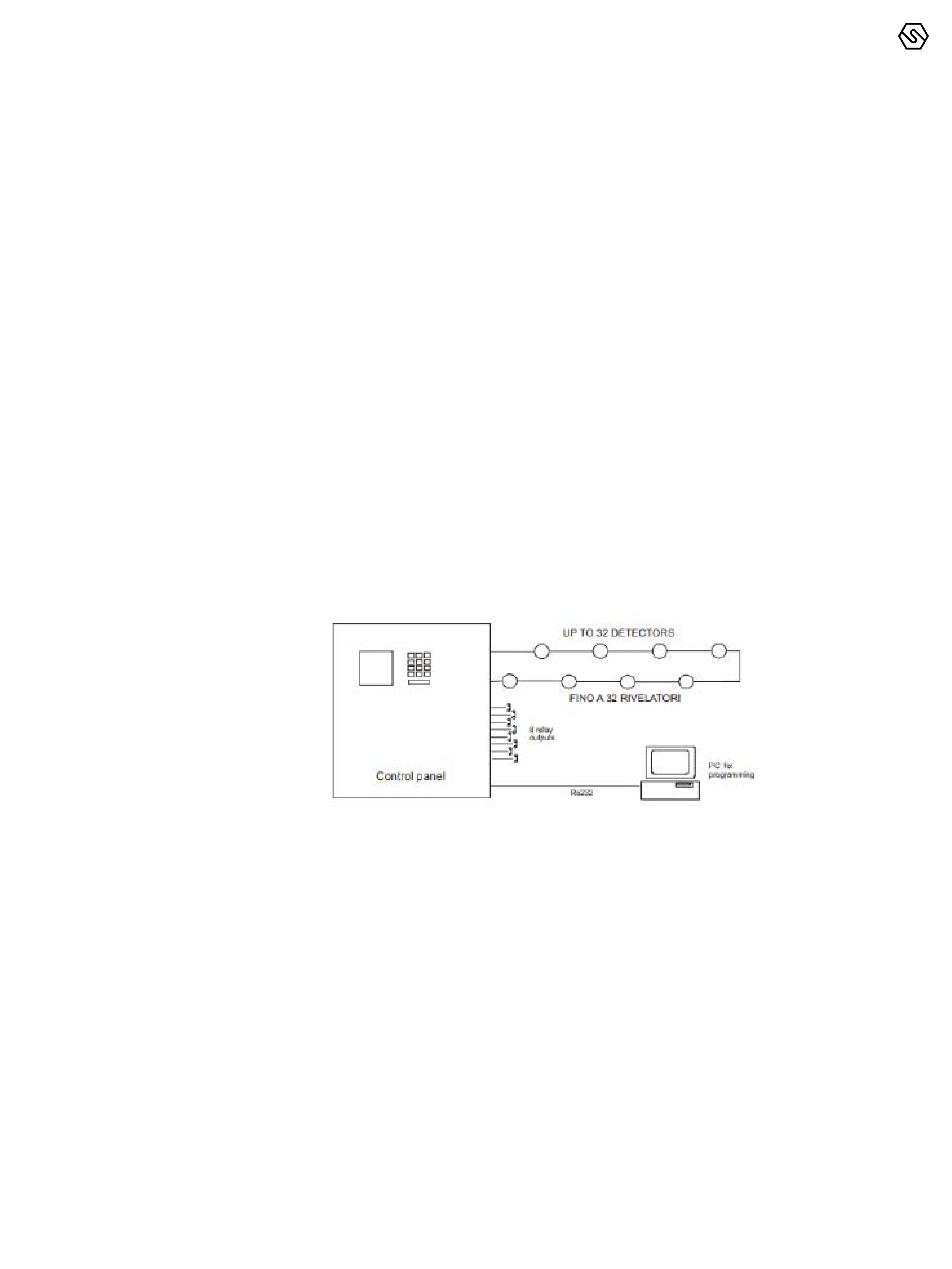
. SERIAL CONNECTION TO A PERSONAL COMPUTER
The control panel can be connected to a Personal Computer using the RS485
serial port, to permit initial programming.
Below the connection to the Personal Computer.
Figure 2.7
Personal computer connection
3. System power up
and operation
The chapter explains the procedures for the operation, the commissioning and
the maintenance of the control unit Galileo 32.
For the programming of the Galileo 32 control panel the PC software is required.
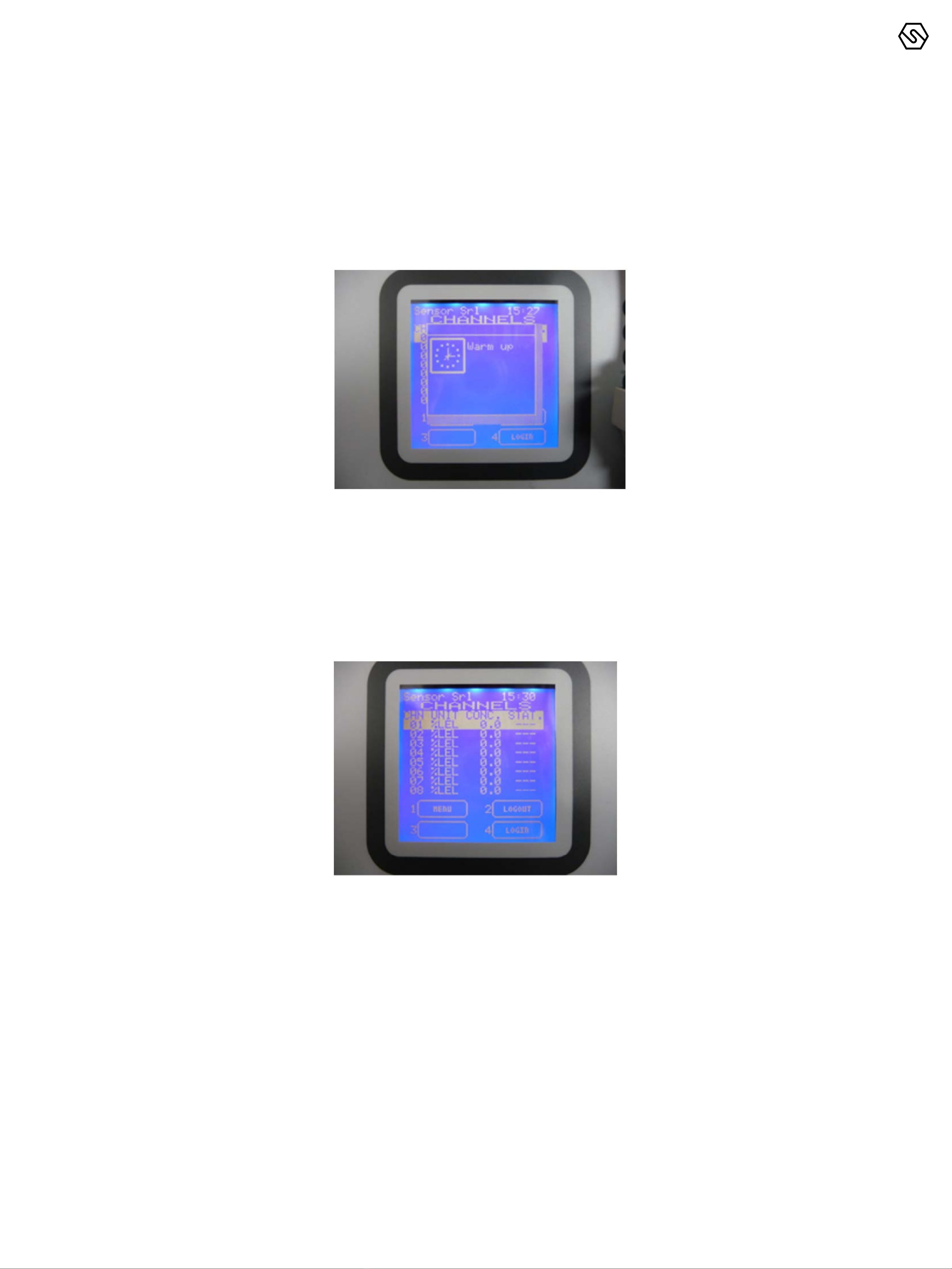
The communication between the user and the central unit is done by means of
an LCD display. In the various system states, various screens will be shown on
display. A few general rules apply at any level as follows:
- Should there is a list displayed, scrolling through may be done using
the UP/DOWN and LEFT/RIGHT arrow keys. Once a selection has been
made, in some menus, pressing ENTER key will switch to a more
detailed view of that particular selection.
All the arrow keys, UP/DOWN, LEFT/RIGHT are being used also to
move through the parameter under change fields.
At any display level, pressing the ESCAPE key instead will switch back
to the previous view. Pressing twice the ESCAPE key will take back to
the main screen.
The same, at any display level, should the keys are not pressed for
more that 3 minutes, the view will automatically switch back to the
main window of the Normal mode.

SENSITRON
A Halma Company
MT2276E
GALILEO 32
Manual (EN)
P. 10/14
. POWER ON
After ensuring correct installation of the Galileo 32, the unit can be switched on.
When first switched on, after the “Warm Up” time (3 minutes by default – pro-
grammable 120-180 seconds) the control panel display will show an empty pi-
cture without any indication because, at the first switch ON, in the control panel
there is not any programming.
Figure 3.1
a) Warm Up screen.
The control panel programming must be performed just by the Personal Com-
puter with the dedicate configuration software (see the previous paragraph for
the connection of the control panel to the PC).
For an already configured control panel, the normal screen will show eight chan-
nels (detectors) with their status:
Figure 3.1
b) Typical NORMAL state screen.

SENSITRON
A Halma Company
MT2276E
GALILEO 32
Manual (EN)
P. 11/14
Figure 3.2
System states diagram.
. SYSTEM STATES
The system is designed so that it may be at a certain moment in one of
following operating modes, which will be comprehensively explained in the
following chapters:
NORMAL
ALARM
FAULT
TEST/MAINTENANCE
UNSET
EMERGENCY

SENSITRON
A Halma Company
MT2276E
GALILEO 32
Manual (EN)
P. 12/14
3.3 NORMAL
This is the system state when everything works properly and there is no Alarm
and no Fault notification. Under this condition it is possible to visualise the cur-
rent status of the inputs.
On LCD display, in the main frame the 8 channels information is shown, with the
actual concentration, as configured in the related channel.
3.4 ALLARM
The alarm condition will be activated according to the settings for each and
every input: The activation conditions are open to programming, but for each
sensor type (in eect each gas revealed) a standard configuration is defined and
loaded by default, when making the settings of a certain input, through the PC
software. In the alarm window the following info is available:
Alarmed channels review, in the case when more than one input are in alarm
state simultaneously, according to the following:
If at a certain point, the signalling made by means of the LCD display of the front
end panel, because of its limited capacity cannot indicate simultaneously all the
gas detectors in alarm state, then the following rules are being applied:
IThe events are ordered by severity, as follows: Over-range, Alarm 3,
Alarm 2, Alarm 1
II Over-range is seen as an Alarm event with the highest severity.
III In the case there are present also other events than alarms, like
faults or emergencies, the alarm events will be in the upper side and
the others in the bottom side of the display
Figure 3.3
Typical NORMAL state screen
Figure 3.4
a) Typical ALARM state of the ACTIVE EVENTS screen

SENSITRON
A Halma Company
MT2276E
GALILEO 32
Manual (EN)
P. 13/14
Pressing Enter key, with a certain alarm event selected, a window is opening
showing the details of the related channel as in the next image:
Figure 3.4
b) ALARM details screen
Figure 3.5
a) Typical FAULT state of the ACTIVE EVENTS screen.
At any access level, by selecting in the main window the 1—Menu and than AC-
TIVE EVENTS sub menu, it is possible to see the gas detectors in alarm state, or
not yet reset.
3.5 FAULT
IShort circuit or open circuit in a detecting circuit
II Removal of a remote gas detector
III Under-scale detection
IV System fault in all the situations presented below at the paragraph
related to EMERGENCY MODE.
Against the fault conditions the following situations have priority:
IAlarm signals, and/or
II Unset of the corresponding gas detector or function, and/or
III Putting under Test the corresponding gas detector or function. This
state is meant for testing and maintenance purpose.
The related function may be tested. A window similar with the one
presented in the subchapter ALARM, will be available on the display.
IV Should the FAULT events are combined with EMERGENCY events,
then the EMERGENCY events will be in the upper side and then the
FAULT events following ordered by date and time, with the most recent
on the top.

SENSITRON
A Halma Company
MT2276E
GALILEO 32
Manual (EN)
P. 14/14
Pressing Enter key, with a certain fault event selected, a window is opening
showing the details of the related channel as in the next image:
Figure 3.5
b) FAULT details screen
3.6 TEST/MAINTENANCE
This state is meant for testing and maintenance purpose. The related function
may be tested following an operations sequence, especially designed for this
purpose. The test/maintenance condition may be activated for each one of the
individual channels.
An user with the OPERATOR or MAINTENANCE level cannot put under TEST/
MAINTENANCE more than 50% of the system’s channels and outputs.
The signals from channels under TEST will be displayed but will not be consid-
ered, in the way that no alarm will be triggered even though the alarm thresholds
are being exceeded.
In the same way, the relays under TEST, will not be activated, even if an alarm
event associated is taking place while the relay is in TEST/MAINTENANCE mode.
EXCEPTION: In the case just one channel is defined, it will be possible to put that
only the channel under test.
The same applies to the case when just one relay is defined. That one relay can
be put under test.
3.7 UNSET
The state is useful for virtually taking o the system various parts, without physi-
cally interrupting the connection.
The UNSET condition may be activated for each one of the individual input chan-
nels and for each one of the 8 relay output.
In the same way as for TEST/MAINTENANCE mode, an user with the OPERATOR
or MAINTENANCE level cannot UNSET more than 50% of the system’s channels
and relays.
The only exception is the ENGINEER level, which may UNSET the whole system
if necessary. It is required to do so for maintenance operations in the installation
where the gas detection systems is installed.

SENSITRON
A Halma Company
MT2276E
GALILEO 32
Manual (EN)
P. 15/14
3.8 EMERGENCY MODE
Special defined state in which the systems switches in case of main unit mal-
functioning or in case of degrading of SIL level, during operation, due to system
faults that may occur.
A typical emergency situation will lead to the following screen: The situations in
which the system should pass into the Emergency Mode are as follows:
AMalfunctioning of one of the two microprocessors from the Main
Board of the Control Unit, detected by the microprocessor itself with
fault notification;
BMalfunctioning of one of the two microprocessors from the Main
Board of the Control Unit, detected by the second microprocessor and
yet the faulty micro still continuing to operate without notifying fault;
CThe microprocessors, memories, multiplexers, DAC’s, relay drivers are
be monitored by a self testing facility implemented into the system’s
hardware and software. The control device will notify a system fault
should the associated procedures related to the self testing functions
are revealing any malfunction.
The system has three user levels and depending on these, various options are
available. The there levels are as follows:
IOPERATOR level (O)
II MAINTENANCE level (M)
III ENGINEER level (E)
Once logged in as a certain level, a letter in the top right side of the screen will
inform about the level, as follows: “O” for Operator. “M” for Maintenance and “E”
for Engineer. If the user is not logged in, the allowed operations are as per Oper-
ator level without the permission to do the “ACK” of the events.
The user passwords can be created and/modified just by the PC configuration
software.
4.1 OPERATOR LEVEL
It is the lowest user level. In all screens the options are at the minimum. The
“Operator” user may only see the system’s configuration. He may browse the
system through channels and relays.
The “Operator” cannot put under Test or take out of Test mode any systems
part, nor he can Unset parts of the system, or Set parts of the system previously
unset. In normal operating mode the display will show the SYSTEM STATE and
will oer the possibility to scroll through the system channels,
The main screen for all user levels is as in the following picture:
4. User levels
Figure 4.1
Typical NORMAL state screen

SENSITRON
A Halma Company
MT2276E
GALILEO 32
Manual (EN)
P. 16/14
In the bottom of the screen, for the “Operator” level there are available the fol-
lowing options:
IMENU, gets the user into a sub menu
II LOGOUT, logs out the active user
III LOGIN, opens the login dialogue window
* See next chapters for details.
In case of Alarm and/or Fault, and/or Emergency the system will switch automat-
ically to ALARM or FAULT or EMERGENCY mode.
The “Operator” user may only ACKNOWLEDGE (ACK) the event, without being
allowed to RESET it.
In eect the only situation when the “Operator” should login is when acknowl-
edging an event. The login is requested for record purposes, thus in the events
log a trace is being kept about the user that acknowledged a particular event.
4.2 MAINTENANCE LEVEL
The “Maintenance” level is the middle user level. Like the “Operator” user, the
“Maintenance” user may see the system’s configuration. He may also browse the
system through channels and relays.
Unlike the “Operator” the “Maintenance” user may also put under Test or take
out of Test mode any systems part, and he can Unset parts of the system, or Set
parts of the system previously unset.
*For more details see the next chapter 5 - MENU’S DETAILS
The operations allowed in the Maintenance level main screen are the same as
for the Operator level plus the option 3 – CHANNEL available for the TEST, SET
and UNSET operation of the channels and the relay.
In case of Alarm and/or Fault, the system will switch automatically to ALARM or
FAULT mode.
*For more details see the next chapter 5 - MENU’S DETAILS
4.3 ENGINEER LEVEL
The operations allowed in the Maintenance level main screen are the same as
for the Maintenance level.
In case of Alarm and/or Fault, the system will switch automatically to ALARM or
FAULT mode.
In eect the only situation when the “ENGINEER” should login is when Reset an
event. The login is requested for making the RESET of Alarm or Fault status. In
the events log a trace is being kept about the user that Reset a particular event.
For more details see the next chapter 5 - MENU’S DETAILS
In the following chapter, the various submenu’s of the main screen will be
detailed:
IMENU, gets the user into an operative menu
II LOGOUT, logs out the active user
III CHANNEL, puts in Test/Maintenance or Set/Unset mode the selected
device
VI LOGIN,opens the login dialogue window
5. Menu’s details

SENSITRON
A Halma Company
MT2276E
GALILEO 32
Manual (EN)
P. 17/14
1 2
34
Sensitron Srl 12.34
34
Sensitron Srl 12.34
CHN UNIT CONC STAT
CHANNELS
01 %LEL 0.0 ----
02 %LEL 0.0 ----
03 %LEL 0.0 ----
04 %LEL 0.0 ----
05 %LEL 0.0 ----
06 %LEL 0.0 ----
07 %LEL 0.0 ----
08 %LEL 0.0 ----
MENU
CHANNELS
LOGOUT
LOGIN
12
34
Sensitron Srl 12.34
MENU
ACTIVE EVENTS
EVENTS LOG
VIEW RELAYS
VIEW CHANNELS
SYSTEM INFO
ESC ENT
1 MENU
34
Sensitron Srl 12.34
MENU
SET
UNSET
TEST
EXIT TEST
ESC ENT
3 CHANNELS
2 LOGOUT
4 LOGIN
PASSWORD
ESCENT
ALARM
XX XXX XXX XX X
12
34
Sensitron Srl 12.34
FULL LOG
XX XXX XXX XX X
XXXXXX
XXX
XXXXX
XXXXXXX
12
34
Sensitron Srl 12.34
RELAYS
XX XXX XXX XX X
XX
XX
XX
XX
12
34
Sensitron Srl 12.34
VIEW CHANNELS
XX XXX XXX XX X
XXXX
XXXXXXXXXXX
XXXXX XXXX XXXX
1 2
34
Sensitron Srl 12.34
SYSTEM INFO
XX XXX XXX XX X
XXXXX
XXX
XXXXXXX
ACK RESET
MENU FILTER
SEL. PERIOD
MENU ACTIV.
RELAY DEACT.
1 2
34
Sensitron Srl 12.34
EVENT
DETAILS
Sensitron Srl 12.34
2 FILTER
ALARMS
FLT&SYST
SETTINGS
FULL LOG
ESC ENT
Sensitron Srl 12.34
ALARMS
EVENTS
LOG
Sensitron Srl 12.34
FLT &
SYSTEM
EVENTS
Sensitron Srl 12.34
SETTINGS
EVENTS
Sensitron Srl 12.34
FULL
EVETS
LOG
Sensitron Srl 12.34
4 SELECT
PERIOD
FROM DATE
TO DATE
ESCENT
Sensitron Srl 12.34
SET
UNSET
TEST
EXIT TEST
ESC ENT
3 RELAYS
Sensitron Srl 12.34
SET
UNSET
TEST
EXIT TEST
ESC ENT
3CHANNELS
WINDOW IN
NORMAL MODE
GALILEO 8/32 CONTROL PANEL
MENU FLOW CHART
M-E
M-E
M-E
M-E
MENULOGOUT
LOGINCHANNEL
M-E
M-E
M-E
M-E
M-E= Maintenance or engineer
user level code is required
default codes:
Operator= 0001
Maintenance=0002
Engigeer=0003
no
submenu
5.1 MENU
In the main window in normal mode, at any user level, one may view the system’s
configuration details, pressing the 1 key.
ACTIVE EVENTS (present just if some active event is present)
EVENT LOG
VIEW REL AYS
VIEW CHANNELS
SYSTEM INFO
5.1.1 ACTIVE EVENTS
Pressing ENT on ACTIVE EVENT the list of the actually active events is shown. If
there are active alarms and active Faults or Emergency situations, they will be
shown by splitting the window in two as below. In the upper side the Alarms and
in the lower side the Faults and Emergency situations. Using the LEFT/RIGHT ar-
row screen will switch between the two sides of the window.

SENSITRON
A Halma Company
MT2276E
GALILEO 32
Manual (EN)
P. 18/14
Figure 5.1.1
a) Active Events screen with Alarm and fault
Figure 5.1.1
b) Active Events screen with alarm only
Figure 5.1.1
c) Active events screen with fault only
Should there are just Alarms or just Faults/Emergency situations they will be
shown in the upper side of the window, respectively.
Below an example of alarm situation only:
Or in case just fault situation is present:
In case of a new event, the screen will switch in automatic to the Active Events
list and the buzzer will sound.
Until the event is acknowledged, the user cannot come back to the main screen.
In the upper figures 5.1.1.a), b) and c) the shown events are not yet acknowledged.
When acknowledged there is a “X” under the column “A”, for the related event.
In this screen there are two buttons:
IACK
II RESET

SENSITRON
A Halma Company
MT2276E
GALILEO 32
Manual (EN)
P. 19/14
IACK
Pressing 1 ACK with the cursor on the active event, will acknowledge it.
There are two situations:
The user is already logged in for a previous operation that requires
login. In this case pressing 1 ACK will simply refresh the screen image
and show an “X” letter on the “A” column (the “Acknowledged” column).
The user is not yet logged in. In this case the LOGIN dialogue window
pops up and the user should key in the password. After which the “X”
letter will be shown under the “A” column of the related active event.
Practically this is the only situation when the login of an “Operator”
level user is required so that a trace is being kept about the person
who acknowledged the active event.
II RESET
Pressing 2 RESET with the cursor on the active event, will reset it, so
the event will disappear from the active events list. Like described abo-
ve there are two situations:
The user is already logged in for a previous operation that requires
ogin. In this case pressing 2 RESET will simply refresh the screen im-
age and delete the event line from the list.
The user is not yet logged in.
In this case the LOGIN dialogue window pops up and the user should key in the
password. After which the screen will be refreshed and the event deleted.
Note
An “Operator” level is NOT allowed to reset active events. He can only acknowl-
edge them so that the display image may be switched back to the main screen.
The reset may only be done by “Maintenance” or “Engineer” level users.
5.1.2 EVENT LOG
In the main window, at any user level, one of the options on the bottom side
menus is EVENTS LOG. Using the up/down arrow keys and then selecting the
“EVENTS LOG” option, followed by ENTER, one enters a submenu. The window
that opens will show the most recent event, in chronological order.
Figure 5.1.2
a) Event detail screen
Using the up/down arrow keys one may scroll through the list.
Using the 2 and 4 keys, one may refine the search
Pressing the ESCAPE key instead will switch back to the main window.
Should 3 minutes pass without any key pressed, the view switches to the Opera-
tor main window.

SENSITRON
A Halma Company
MT2276E
GALILEO 32
Manual (EN)
P. 20/14
IV SELECT PERIOD
Opens a query asking to select the period to be observed by entering
the start and the end date.
The date should be introduced in a 2 digit format for day, month and year: “DD/
MM/YY”.
As the dialogue window opens, the cursor is already in the “DD” field waiting for
the day to be introduced. Keying in the day, the cursor will automatically move to
the “MM” field waiting for the month to be keyed in. The same for the year after
which the cursor moves to the end date “DD” field and the procedure repeats
for the introduction of the complete end date. In the end, pressing ENTER, the
window will next show only the selected period events.
Using the up/down arrow keys one may scroll through the new list.
To exit this view and come back to the main window press ESCAPE key.
II FILTER
In any of the events views, pressing the 2 key Filter, enters in a
submenu of the Event Log. Using the up/down arrow keys one may
scroll through the list.
FULL LOG
The FULL LOG option shows all the events, in chronological order,
starting with the most recent. Using the up/down arrow keys one may
search in the event log.
FLT & SYSTEM
Choosing the Fault & System LOG option enters the faults and system
events list. Using the up/down arrow keys one may search in the Flt &
fault event log.
Figure 5.1.2
b) Select period dialogue window
Figure 5.1.2
c) FILTER options screen
Table of contents
Other Halma Control Panel manuals

Halma
Halma Ampac ZoneSense Plus Instruction Manual

Halma
Halma Ampac SmartTerminal AS7240 Operating instructions

Halma
Halma Ampac LoopSense Operating instructions

Halma
Halma Ampac LoopSense Guide

Halma
Halma Ampac FireFinder Guide

Halma
Halma SENSITRON MULTISCAN++ PK-32 User manual

Halma
Halma ZoneSense Plus AS User manual
Popular Control Panel manuals by other brands

tau
tau K100M installation guide

Gilson
Gilson HM-630 operating manual

Lince
Lince GOLD 869 MST Series Installation, operation and maintenance manual

Tenways
Tenways Thermopad user manual

BadgePass
BadgePass BP 1501 Quick reference guide

Siemens
Siemens Cerberus PYROTRONICS MXL Operation, installation, and maintenance manual