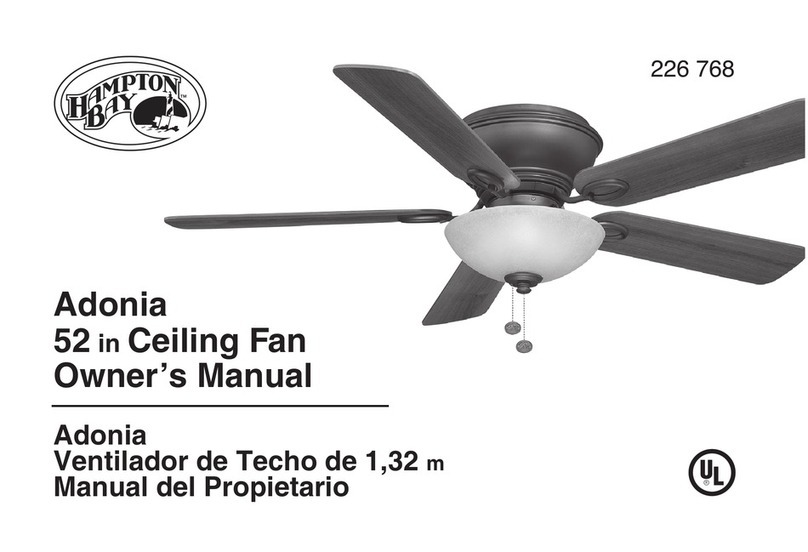
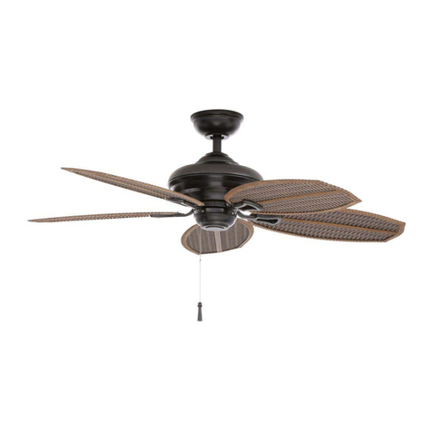
HAMPTON BAY 285-962 User manual
Other HAMPTON BAY Fan manuals

HAMPTON BAY
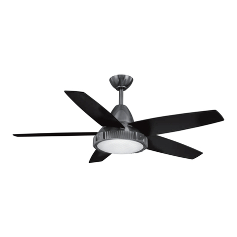
HAMPTON BAY 394-443 User manual
HAMPTON BAY
HAMPTON BAY Thorton User manual

HAMPTON BAY
HAMPTON BAY Victoria User manual
HAMPTON BAY
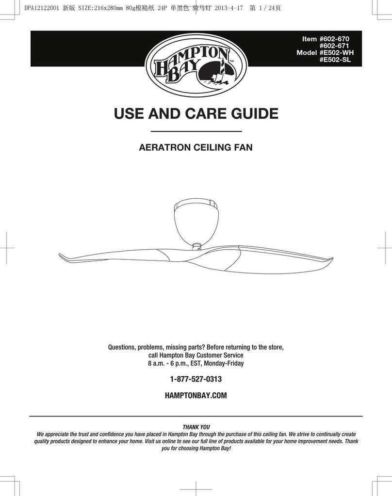
HAMPTON BAY AERATRON User manual
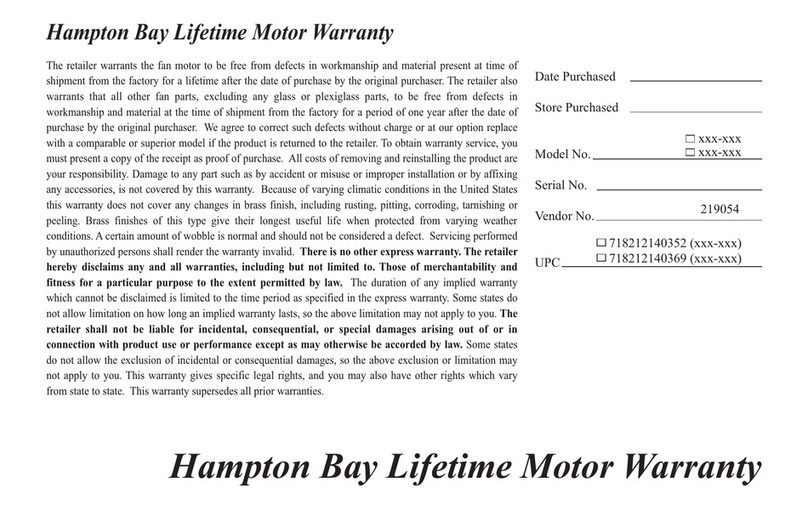
HAMPTON BAY
HAMPTON BAY 132 cm Fan User manual
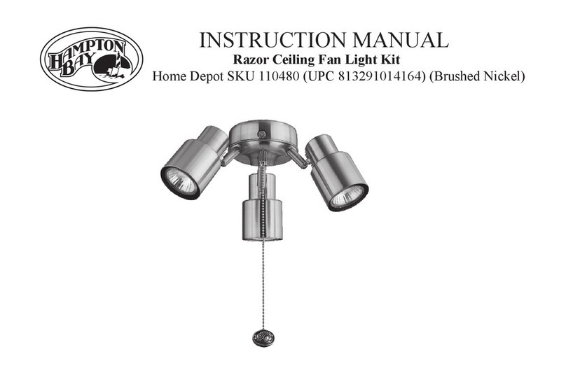
HAMPTON BAY
HAMPTON BAY Razor User manual
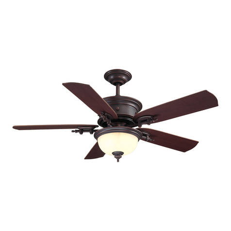
HAMPTON BAY
HAMPTON BAY Dawson 581 645 User manual
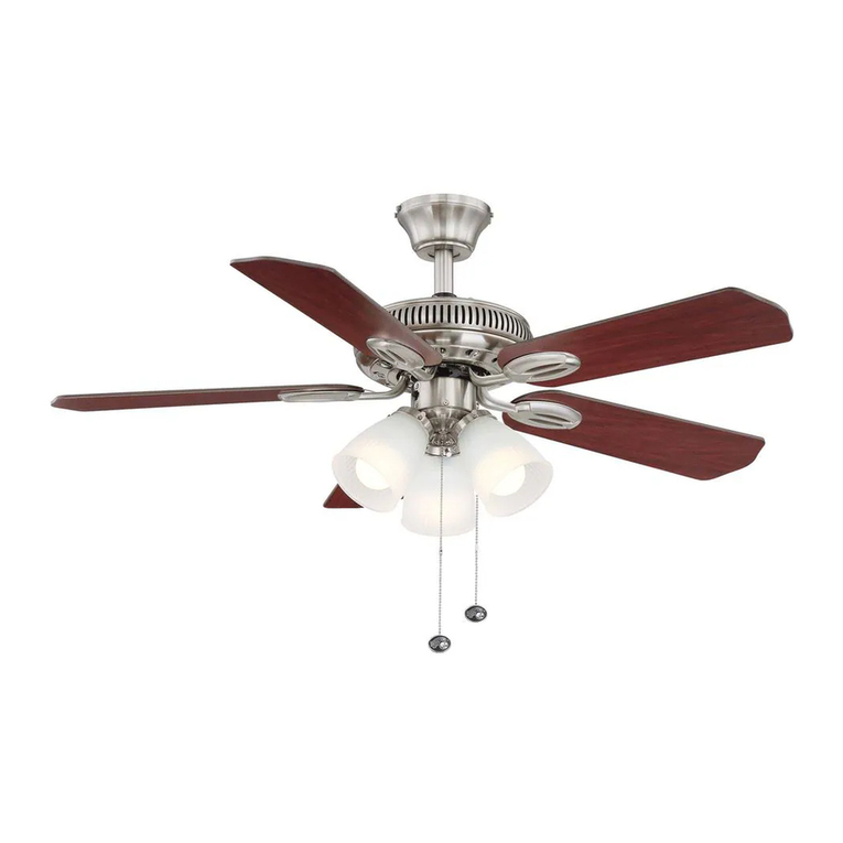
HAMPTON BAY
HAMPTON BAY Glendale User manual
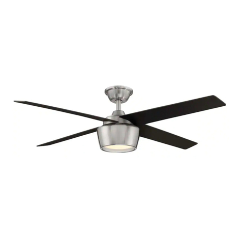
HAMPTON BAY
HAMPTON BAY YG763-BN User manual

HAMPTON BAY
HAMPTON BAY ASHBURTON YG593-WH User manual

HAMPTON BAY
HAMPTON BAY Middleton 42 inch User manual

HAMPTON BAY
HAMPTON BAY YG529-WH User manual
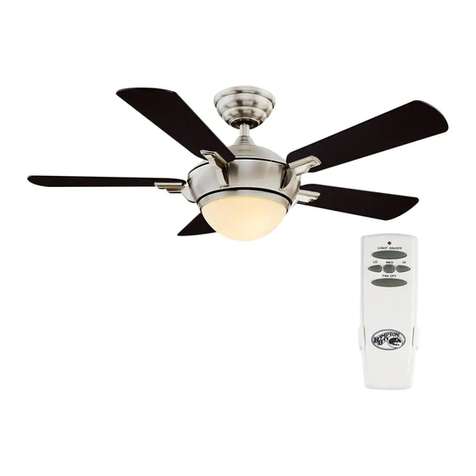
HAMPTON BAY
HAMPTON BAY Midili User manual

HAMPTON BAY
HAMPTON BAY Isolabella User manual

HAMPTON BAY
HAMPTON BAY Vasner User manual

HAMPTON BAY
HAMPTON BAY WELLSTON 51360 User manual

HAMPTON BAY
HAMPTON BAY 1005 819 968 User manual
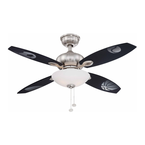
HAMPTON BAY
HAMPTON BAY AM213-BN User manual

HAMPTON BAY
HAMPTON BAY PORTSMOUTH 51355 User manual

HAMPTON BAY
HAMPTON BAY NORTH POND 51716 User manual
Popular Fan manuals by other brands

ELTA FANS
ELTA FANS H03VV-F installation guide

Hunter
Hunter 20714 Owner's guide and installation manual

Emerson
Emerson CARRERA VERANDA CF542ORB00 owner's manual

Hunter
Hunter Caraway Owner's guide and installation manual

Panasonic
Panasonic FV-15NLFS1 Service manual

Kompernass
Kompernass KH 1150 operating instructions


