HandyHeat Carbon Film User manual

Contents
Page 2 Product Overview
Page 3 Pre-Installation & Electrical Provision
Page 4 Insulation Underlay - Installation
Page 5 Carbon Film Installation - Under Wood/Laminate Flooring
Page 8 Notes & Trouble shooting
Carbon Film
Installation Instructions
Revision 4, 13/02/07

Carbon Film
Installation Instructions
Page 2
Cold Tail Joint
Cutting Marks
Insulation Tab
Cold Tail
Copper Conductor Strip
Clear Spoils
Product Overview
Thank you for selecting our electric underfloor heating system. Before you begin installing please read through these
instructions carefully & check that you have all the components required.
The system requires a mains voltage 230V supply & must be connected in compliance with building regulation Part 'P'
approved document and IEE 16th Edition
Contents of Heating Kit:
• Carbon heating film with cold connections made
• 6mm Foam Insulation Underlay
• Digital Programmable Thermostat
• Floor Probe
• Floor plan showing element layout
• 20Amp push fit cable connectors & connection box
• Polyethylene Sheet (Moisture Barrier)
• Factory test sheet with individual resistance readings
• Warranty / Guarantee Certificate
Important Notes:
Due to their moisture content, solid and kiln dried wood floor coverings should be laid, but not fixed, to allow acclimatisa-
tion with the heating system energised before final fixing. Allowances should be made for expansion. Refer to manufac-
turers instructions.
Laminate and veneered/engineered flooring needs to have an allowance made for expansion. Refer to manufacturers
instructions
The Carbon Heating Film, when installed under a wood floor, will heat the floor to a temperature of 27°C. This is the limit
to which most wood floors can be heated to. Consult wood flooring manufactures technical details for further information.
Please note that the surface temperature of the wood flooring under rugs and flush or low profile furniture may exceed
27°C if not monitored.
If other floor finishes are to be installed over the carbon film, e.g. Carpet, Vinyl etc, a stable floating floor must be con-
structed. Heat-Pak® flooring is recommended for this application, which is available from your underfloor heating supplier,
to give a smooth and thermally conductive sub-floor.

Carbon Film
Installation Instructions
Page 3
Isolated Mains Supply (230V~)
Cold Tails to
Electrical Supply from
15Amp Max to each thermostat
Floor
Probe
25mm Deep Minimum
Blank Fronted Junction Box
Thermostat to Junction Box
Heating Elements
Thermostat
Digital
First unpack & identify all components (a list of supplied
components is on page 2) and check the layout - see sup-
plied floor plan (example Fig. 2)
Ensure that the sub-floor (concrete or timber) is clean, dry &
free from dust & debris. The floor should also be suitably
level to take the kind of flooring that you will be laying. Some
types of wood plank flooring have a tolerance of just a mm
or two per linear metre & we strongly recommend that your
floor fitter surveys the floor before the heating is installed.
Make the electrical provision as per the diagram Fig.3.
The circuit must incorporate a 30mA RCD protection
For installations below 13Amp, A fused spur or combined
spur/ RCD is recommended.
For installations over 13Amp a suitable isolated supply should
be provided incorporating 30mA RCD protection.
The thermostat rating is 15amps & this is capable of control-
ling approx 3450watts of heating film (most domestic installa-
tions are within this figure). If the system supplied is over
3.45kW it will be subject to a more comprehensive electrical
installation. (Your electrician will be able to advise you on
this).
Note: all electrical connections should be made in compliance
with building regulation Part 'P' and the IEE 16th Edition.
Fig. 2
Fig. 3
Additional items to aid installation
Stanley/Craft Knife
Double Sided Adhesive Tape
Self Adhesive Cloth Tape (Duct Tape)
Multi-Meter
Pre-Installation
Electrical Provision
A E
D
B C

Carbon Film
Installation Instructions
Page 4
Step 1
Once you are satisfied that the sub-floor is suitable (see pre-
installation notes page 3), lay out the insulation underlay to
cover the entire floor area, except for the 50mm gap. The
foam underlay sheets should be laid with staggered joints
Fig.4.
If laying a double layer (recommended in conservatories &
other areas with a high heat loss) the second layer should
be laid at right angles to the first.
Notes:
The foam underlay should be cut with a Stanley knife or similar.
Step 2
Leave a gap of approximately 50mm at one edge of the room along where the cold cables are to be run, so as to allow
them to sit flush under the floor covering when it is laid. For systems of more than 8 elements a gap wider than 50mm may
be required.
Using a length of 50mm wide double sided tape on the sub floor within the gap that has been made in the underlay, can
be used to hold the cold cables in place.
Step 3
If you wish, you can join the sheets of underlay together to
prevent them from moving apart. This can be done by
taping the edges of adjoining sheets together with a self
adhesive cloth tape (Duct Tape) Fig. 5
Fig. 4
Fig. 5
Insulation Underlay - Installation

Carbon Film
Installation Instructions
Page 5
Check the resistance of each element using a suitable
electrical testing device.
A basic multi-meter will be sufficient to test the elements
at this stage.
You can purchase a suitable test device from your un-
derfloor heating supplier or most DIY stores stock similar
products.
DO NOT continue without first testing each element.
The desired resistance readings for each element are
listed on the enclosed room test data sheet. A sample of
the data sheet is shown in fig. 6. The reading should be
within the Design Resistance Reading Range e.g a
reading of 223Ω for the range circled in the example fig
6 is acceptable.
Note. The cold cables are double
Insulated, a coloured outer and a clear inner.
Carbon Film Installation
Under Wood/Laminate Flooring
Only LIGHT FOOTWARE should be worn . Avoid foot traffic on the heating elements and cold tail joints.
Un-pack the heating elements for the room and check that you have all the elements detailed on the enclosed drawing &
room test data sheet.
Step 4
Fig. 6
Step 5
Step 6
Position the rolled up elements along the edge of the room Fig.7, as per the drawing supplied. When you are satisfied with
the position of the elements (ensuring that they will not overlap), roll out the heating elements Fig.8. The elements can be
laid either way up, however we recommend they are installed copper face down to aid recessing the cold tail connections
into the insulation underlay.
Adjust positioning to obtain the best floor coverage and lightly fix into position with self adhesive cloth tape (duct tape) to
avoid movement.
Fig. 7 Fig. 8

Carbon Film
Installation Instructions
Page 6
If used, peel the backing from the double sided tape that was fixed
into the 50mm gap at the edge of the room.
Starting from the point furthest from the connection box, run the cold tails from each element along the room perimeter,
fixing them to the exposed double sided tape or if tape is not used, lay them carefully in the gap.
DO NOT run the cold tails under the heating elements
Below each of the “cold tail” joints form a cut out in the foam un-
derlay to allow the plastic cover of the joint and the cold tail itself
to lay within the underlay. Fig. 9
The cut out for the cold tail should extend to the 50mm gap at the
edge of the room.
If you have installed more than one layer of foam underlay, only
form the cut-outs in the top layer.
Step 7
Step 8
Fig. 9
Step 9
Once the cold tails are in position a resistance test needs to be per-
formed on each individual element for a second time. The desired
resistance readings for each element are listed on the enclosed room
test data sheet.
Record the actual reading in the box provided on the data sheet.
This is a requirement of the guarantee and MUST be performed
at this stage. The data sheet needs to be retained on site with the
heating system.
Note. The cold cables are double insulated, a coloured outer
and a clear inner.
Fig. 10
The cold tails can now be joined in parallel at the junction box
using the 8-way electrical connectors provided.
The junction box should be a double gang blank fronted box of a
minimum 25mm depth. Fig. 11
The paralleled cold tails should be routed to the junction box and
connected to a suitably sized supply cable from the thermostat.
See Fig. 2 Page 3
Note. The cold cables are double insulated, a
coloured outer and a clear inner.
Step 10
Fig. 11

Carbon Film
Installation Instructions
Page 7
Sensor Tip
50mm Gap
Depron
Cold Tails
Cold Tails
Step 11
Fig. 12
Position the floor sensor. If installing Heat-Pak® over the carbon system, refer to separate instructions regarding the floor
sensor.
For standard installation, the tip of the sensor should be approximately 300-500mm from the edge of the room with the tail
of the probe running back to the thermostat via the 50mm cold tail gap. Fig. 12. Form a channel in the foam underlay, in
between two of the elements running into the cold tail gap. Press the sensor into the channel and tape in place with self
adhesive cloth tape.
The sensor wire can be shortened or if required lengthened up to 50m with a minimum 0.75mm² 2-core flex cable. This
connection should be located above floor level ideally within the cold tail junction box.
It is advisable to mark on the installed location of the sensor tip, on the floor plan for future reference.
Test the resistance of the floor probe. Refer to the label on the floor probe wrapper for desired resistance readings. Make
a note of the reading.
When you are satisfied with the layout, cover the heating elements with the plastic sheet/moisture barrier provided. The
grade of PE-Sheet supplied will depend upon what is being installed over the system. If a wood floor, engineered wood or
laminate floor is being laid, a 100micron sheet (clear) will be provided. When fitting Heat-Pak® over a carbon heating sys-
tem a 200micron sheet (coloured blue) has to be used. The joints of the sheeting have to overlap by at least 20 cm. These
overlaps have to be sealed over their total length with a self-adhesive PVC cloth tape (Duct Tape)
Step 12
The floor finish can now be laid directly over the moisture barrier in accordance with the flooring manufacturers instruc-
tions. Under no circumstances should a separate underlay be installed at any point between the heating element and
the floor finish. Ensure that the floor finish has been acclimatised prior to installation to avoid excessive shrinkage when
heated. Refer to the notes on page 2 of this manual.
During the process of laying the floor, care should be taken not to damage any of the heating elements or cold tails. A
spare sheet of foam underlay or a board, can be used to kneel on to help spread weight.
Step 13
Once the floor finish has been laid, perform resistance tests on the floor probe and across the feed cable that connects the
thermostat to the junction box, to ensure that no elements have been damaged during the flooring installation. The desired
resistance reading for the heating system is at the bottom of the room test data sheet and should be within the tolerance of
+10 –5%. Record the final readings on the guarantee certificate.
Once this test has been completed, final connections to the thermostat can be made. See Separate installation instruc-
tions for the thermostat.
Step 14

Carbon Film
Installation Instructions
Page 8
1. Electric underfloor heating is designed to run at low temperatures and can have a slightly slower warm-up time than
conventional heating. This can be countered by using the features of the programmable thermostat instead of
switching the system on or off.
2. If installed in new buildings and especially conservatories, the heating period may be affected by the moisture con-
tent within the building. All new floor constructions and new buildings should be fully dried out before fitting wood,
engineered wood or laminate flooring.
3. The carbon film heating system is primarily designed to heat wood, engineered wood or laminate flooring. With such
materials it is important to control the temperature to which they are heated. The industry standard for most wood
flooring products is 27°C. Be aware that the carbon film heating system is capable of heating above this tempera-
ture and is only limited by the thermostat and the temperatures that it is set to operate to.
Notes
Electrical Notes
To satisfy the requirements of an acceptable British Standard a double sheathed single core cable to BS.6004 must be
used under floors. All our cold cables comply to this standard.
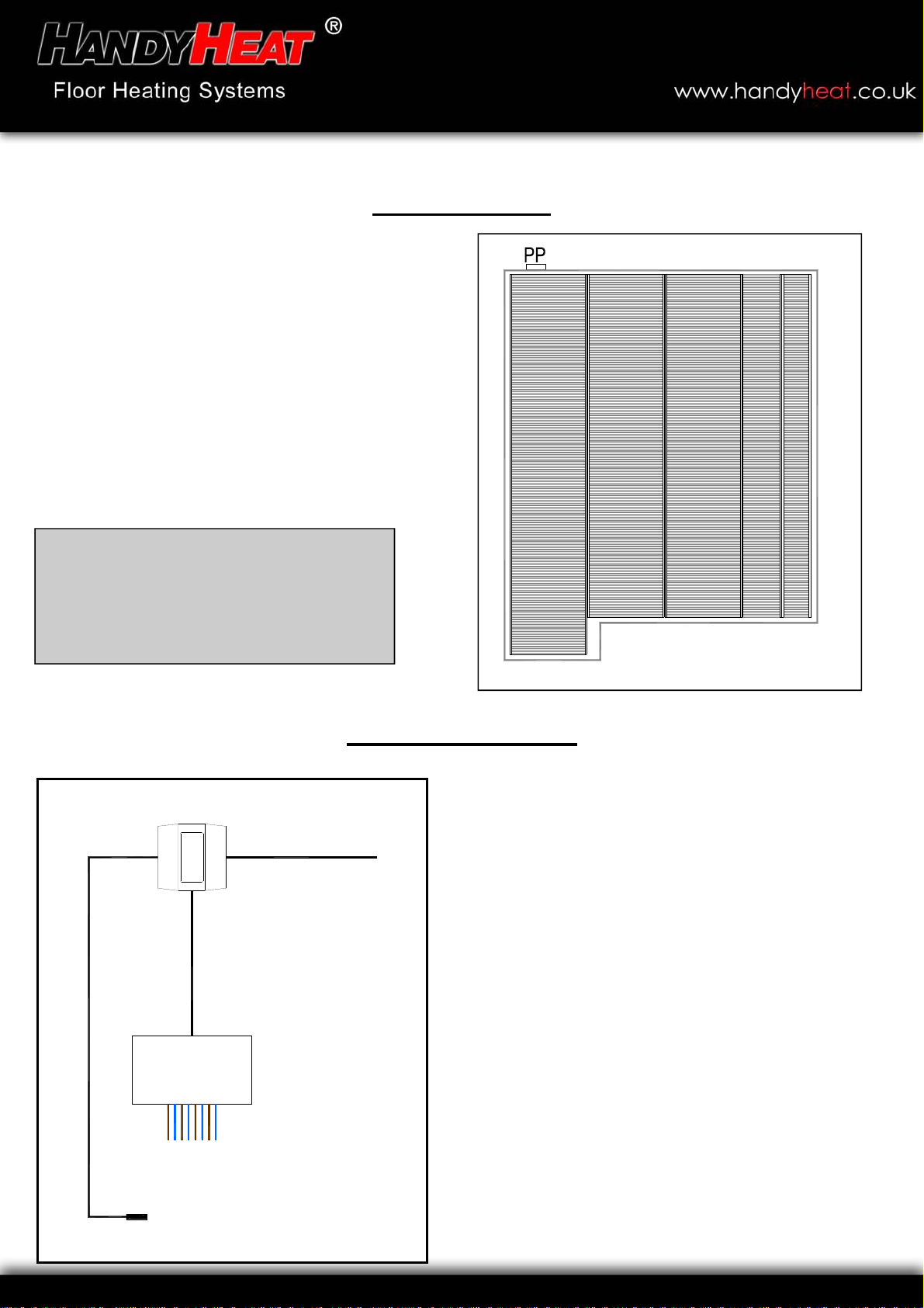
Each individual heating element is designed to accommodate a current carrying capacity of up to 10Amps and should be
connected in parallel at the junction box.
Consideration must be given by the electrical contractor in respect of the individual heating circuit ratings relative to the
thermostat rating, circuit breakers, interconnecting cable sizing and switched contactors where the load of the heating
system exceeds the rating of a single thermostat. Good wiring practice must be observed and the wiring must comply
with the IEE 16th edition regulations.
The electrical installation must incorporate a 30mA RCD Protection
Trouble shooting and FAQ’s
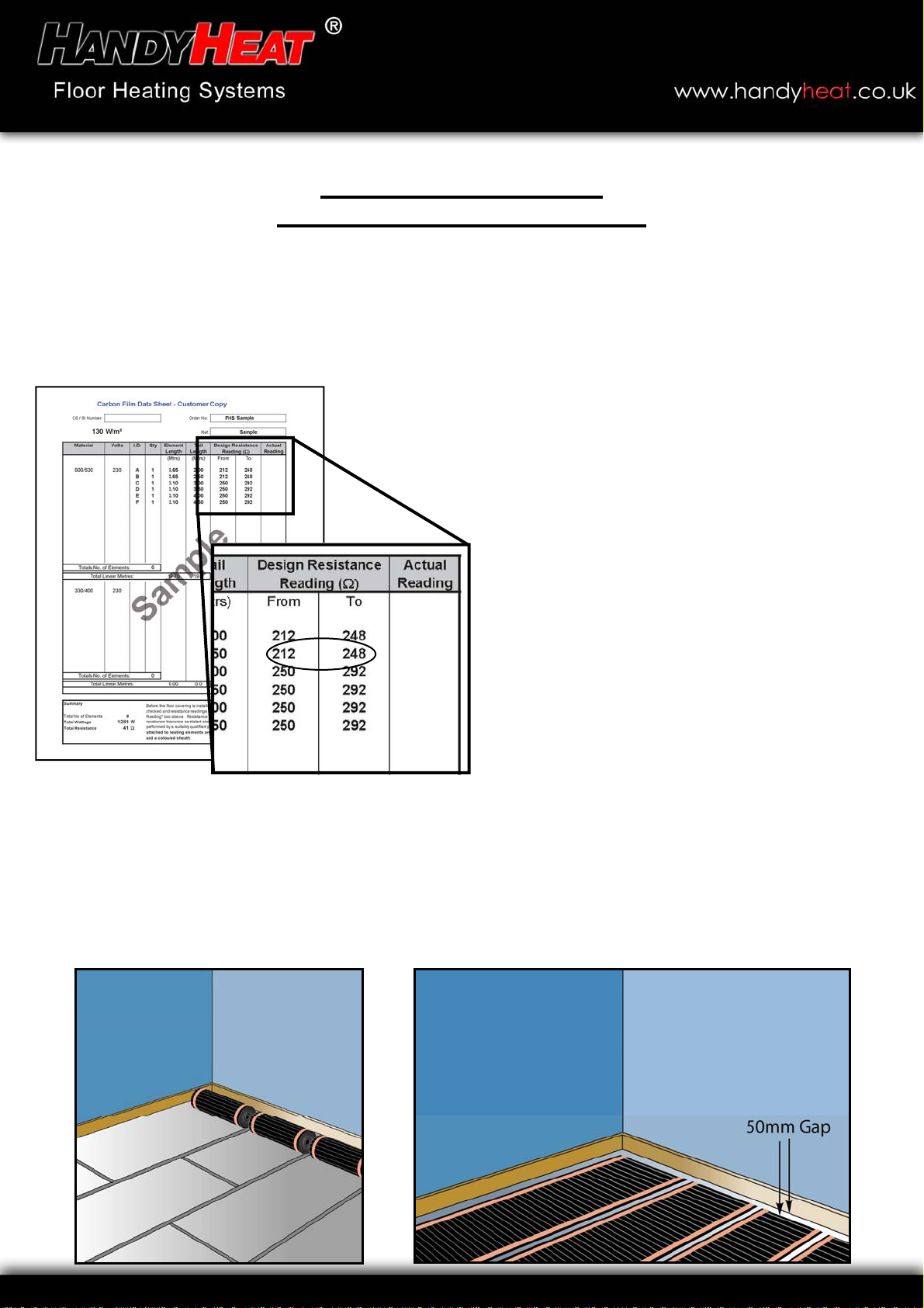
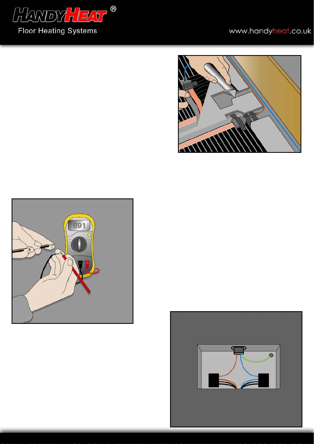
Q. When I perform the resistance test on the heating element I cannot get a reading.
A. Check that the test equipment you are using is set to read Ωand that both the inner and outer cable insulation
sheaths have been removed.
Q. What size cable should be used to connect the thermostat to the junction box?
A. The size of the cable will vary depending upon the electrical load required for the heating system. Therefore this ca-
ble needs to be correctly sized by the electrician.
Q. The heating elements are slightly too long, can they be cut?
A. Yes. The element should be cut across it’s width, along a clear section, in line with the cutting marks on either edge
of the element. Once cut, the ends of the copper conductors need to be sealed either re-using the green stickers
from the end of the off-cut or use electrical insulation tape.
Q. Can the elements be overlapped?
A. Under no circumstances should the heated areas of the elements be overlapped. Only the clear spoils at the edge
of the element can be over lapped
For help and advice regarding this product, please contact the Floor Heating Helpline: 0870 199 7842
These instructions are correct at time of writing
Table of contents