suntouch TapeMat D12 Series User manual

Installation Manual
TapeMat®
Please be aware local codes may require this product and/or the thermostatic control to
be installed or connected by an electrician. Please leave this manual with the end user.
Includes Custom TapeMat® and ShowerMat™
Series D12,
C12 & C15
Assembled in the
USA

IOM-WR-TapeMat 1526 2 of 32
Read this Manual BEFORE using this equipment.
Failure to read and follow all safety and use information can result
in death, serious personal injury, property damage, or damage
to the equipment.
Keep this Manual for future reference.
Specifications for TapeMat:
Floor heating mats are a simple way to heat an indoor space. This instruction manual is
provided as a guide to installing TapeMats, including design considerations, installation steps,
limitations, precautions, and floor covering guidelines.
TapeMat is a complete heating mat consisting of a series heating wire and a power lead for
connection to the electric power supply.
The heating wire length cannot be cut to fit.
Controls:
TapeMats must be controlled by a SunStat
®
floor sensing thermostat. (Listed separately)
Voltage:
120 VAC, 240 VAC, 1-phase (see Table 2)
Watts:
D12 and C12 Series - 12 W/ft
2
(41 Btu/h/ft
2
), C15 Series 15 W/ft
2
(51 Btu/h/ft
2
)
Maximum circuit load:
15 A
Maximum circuit overload protection:
20 A breaker
GFCI:
(Ground Fault Circuit Interrupter) required for each circuit (included in the SunStat control)
Listing:
UL Listed for U.S. and Canada under UL 1693 and CAN/CSA C22.2 No. 130.2-93,
File No. E185866
Application:
Indoor floor heating only (-X on the nameplate label indicates CUL Listing for this
application).
Suitable for installation in a shower area (see Step 3.10 for restrictions). (-W on
the nameplate label indicates CUL Listing for Wet Location in Canada per Canadian Electrical
Code, Part I (CEC).
Embedded in polymer-modified cement based mortar only (see Phase 4).
D12 and C12 Series - May be installed under masonry or non-masonry surfaces as indicated
in this manual.
C15 Series - May only be installed
under masonry surfaces as indicated
in this manual.
Minimum bend radius:
1 inch
Maximum exposure temperature:
(Continuous and storage)
194ºF (90ºC)
Minimum installation
temperature:
50ºF (10ºC)
Installation must be performed by qualified persons, in accordance with local codes, ANSI/
NFPA 70 (NEC Article 424) and CEC Part 1 Section 62 where applicable. Prior to installation,
please consult the local codes in order to understand what is acceptable. To the extent this
information is not consistent with local codes, the local codes should be followed. However,
electrical wiring is required from a circuit breaker or other electrical circuit to the control.
It is recommended that an electrician perform these installation steps. Please be aware
local codes may require this product and/or the control to be installed by an electrician.
Double-
sided Tape
Heating Wire
Factory Splice
Power lead
Mat Mesh

3 of 32 © 2015 Watts Water Technologies
Expected floor temperature
Heating performance is never guaranteed. The floor temperature attainable is dependent on
how well the floor is insulated, the temperature of the floor before start up, and the overall
thermal drain of the floor mass. Insulation is required for best performance. Refer to Phase 4
for important design considerations.
Important Safety Information
This is a safety-alert symbol. The safety alert symbol is shown alone or used with
a signal word (DANGER, WARNING, or CAUTION), a pictorial and/or a safety
message to identify hazards.
When you see this symbol alone or with a signal word on your equipment or in
this Manual, be alert to the potential for death or serious personal injury.
This pictorial alerts you to electricity, electrocution, and shock hazards.
This symbol identifies hazards which, if not avoided, could result in death
or serious injury.
This symbol identifies hazards which, if not avoided, could result in minor
or moderate injury.
This symbol identifies practices, actions, or failure to act which could result
in property damage or damage to the equipment.
Table of Contents
Important Safety Information.....................3
Phase 1 - Preparations ..............................5
Phase 2 - Electrical Rough-in ....................9
Phase 3 - TapeMat Installation ................ 11
Phase 4 - Floor Coverings ....................... 17
Phase 5 - Control Installation ..................20
Appendices ..............................................22
Troubleshooting .......................................29
Warranty...................................................31
These are the three most common installations:
1.
Wood framing:
With the mat installed on a well-insulated wood subfloor, and thin-set mortar
and tile on top, most floors can be heated up to 20°F warmer than they would otherwise be.
2. Insulated concrete slab:
With the mat installed on an insulated concrete slab, and thin-set
mortar and tile on top, most floors can be heated up to perhaps 15°F warmer than they
would otherwise be.
3.
Uninsulated concrete slab:
With the mat installed on an uninsulated concrete slab, and
thin-set mortar and tile on top, most floors can be heated up to perhaps 10°–15°F warmer
than they would otherwise be.
Please consult a designer or the factory if questions remain about the surface temperature
that can be expected from the cables in any particular construction.

IOM-WR-TapeMat 1526 4 of 32
NEVER install TapeMat under carpet, wood, vinyl, or other non-masonry flooring without
embedding it in thin-set, thick-set, or self-leveling mortar.
NEVER install TapeMat in adhesives or glues intended for vinyl tile or other laminate flooring, or
in pre-mix mortars. It must be embedded in polymer-modified, cement based mortar.
NEVER cut the heating wire. Doing so will cause dangerous overheating and will void the
warranty. The power lead may be cut shorter if necessary, but never remove completely
from the heating wire.
NEVER bang a trowel or other tool on the heating wire. Be careful not to nick, cut, or pinch
the wire causing it to be damaged.
NEVER use nails, staples, or similar to fasten the heating wire to the floor.
NEVER attempt to repair a damaged heating wire, splice, or power lead using unauthorized
parts. Use only factory authorized repair parts and methods.
NEVER attempt to repair a damaged shower mat. It must be replaced.
NEVER splice one mat heating wire to another mat heating wire to make a longer mat. Multiple
mat power leads must be connected in parallel in a junction box or to the thermostat.
NEVER install one mat on top of another or overlap the heating wire on itself. This will cause
dangerous overheating.
NEVER forget to install the floor sensor included with the thermostat.
NEVER install TapeMat in any walls, or over walls or partitions that extend to the ceiling.
NEVER install mats under cabinets or other built-ins having no floor clearance, or in small
closets. Excessive heat will build up in these confined spaces, and the mat can be
damaged by fasteners (nails, screws, etc.) used to install built-ins.
NEVER remove the nameplate label from the power leads. Make sure it is viewable for
inspection later.
NEVER extend the heating wire beyond the room or area in which it originates.
NEVER allow a power lead or sensor wire to cross over or under a heating cable. Damage
could result.
NEVER put the system into full operation until the tile or flooring installer verifies all cement
materials are fully cured (typically two to four weeks).
Table 1
As with any electrical product, care should be taken to guard against the
potential risk of fire, electric shock, and injury to persons. The following
cautions must be observed:
Local building or electrical codes may require modifications to the information provided.
You are required to consult the local building and electrical codes prior to installation. If
this information is not consistent with local building or electrical codes, the local codes
should be followed.
ALWAYS completely embed the heating wire and factory splices in the floor mortar.
ALWAYS maintain a minimum of 2.5" spacing between heating wires.

5 of 32 © 2015 Watts Water Technologies
Installation must be performed by qualified personnel, in accordance with local codes and
standards. A licensed electrician is recommended.
Phase 1 - Preparations
ALWAYS pay close attention to voltage and amperage requirements of the breaker, the
thermostat, and the TapeMat. For instance, do not supply 240 VAC power to 120
VAC TapeMat as damage will result.
ALWAYS make sure all electrical work is done by qualified persons in accordance with local
building and electrical codes, Section 62 of the Canadian Electrical Code (CEC)
Part I, and the National Electrical Code (NEC), especially Article 424.
ALWAYS use copper only as supply conductors to the thermostat. Do not use aluminum.
ALWAYS seek help if a problem arises. If ever in doubt about the correct installation procedure
to follow, or if the product appears to be damaged, the factory must be called before
proceeding with the installation.
Before installing TapeMat, make sure to fully inspect the products and carefully plan the site.
Items Needed
Materials:
• SunStat thermostat control with floor sensor.
• SunStat Relay control (if required)
•
Control electrical box (UL Listed, extra deep, see control instructions for size and type required)
• Junction electric box (if required, see Step 2.2)
• Wire nuts (Must be UL Listed and proper size)
• Flexible or rigid conduit (if required, see Step 2.4, must be UL Listed and proper size)
• 12-gauge or 14-gauge electrical wiring cable (consult local code)
• Nail plate (see Step 3.8)
Tools:
• Digital multi-meter for ohms testing; must read up to 20,000 ohms to measure sensor
• Drill with 1/2" & 3/4" bits
• Hammer and chisel
• Hot glue gun and hot glue (craft grade)
• Wire strippers
• Phillips screwdriver
• Fish tape
• Hole saw
• Floor covering installation tools
Floor sensor is
included in the
SunStat thermostat
packaging. This must
be installed in the
floor with the mat.

IOM-WR-TapeMat 1526 6 of 32
It is important to select the proper size mat for the given area. Mats cannot be cut shorter
in order to fit a given area. Doing so will damage the heating wire and prevent the system
from working.
Please check the product label for exact ratings. This table is for reference only.
Table 2 - Mat Sizes
Inspect mat, control, and sensor
To prevent the risk of personal injury and/or death, make sure power is not
applied to the product until it is fully installed and ready for final testing. All
work must be done with power turned off to the circuit being worked on.
STEP 1.1
Remove the TapeMat, SunStat Control, and sensor from their packages. Inspect them for any
visible damage and verify everything is the correct size and type according to the plan and
the order. Do not attempt to install a damaged product.
120 VAC TapeMat
2 ft Wide
Mat
Ft2
Mat Size
(W x L)
Model
Number
Amp
Draw
Ohms
10 2' x 5' 12000524 1.0 109 - 134
15 2' x 7'-6" 12000724 1.5 76 - 94
20 2' x 10' 12001024 2.0 57 - 71
25 2' x 12'-6" 12001224 2.5 43 - 54
30 2' x 15' 12001524 3.0 34 - 42
35 2' x 17'-6" 12001724 3.5 29 - 36
40 2' x 20' 12002024 4.0 25 - 32
45 2' x 22'-6" 12002224 4.5 22 - 28
50 2' x 25' 12002524 5.0 20 - 26
60 2' x 30' 12003024 6.0 17 - 21
70 2' x 35' 12003524 7.0 14 - 18
80 2' x 40' 12004024 8.0 12 - 16
90 2' x 45' 12004524 9.0 11-14
100 2' x 50' 12005024 10.0 10-13
3 ft Wide
15 3' x 5' 12000536 1.5 76 - 95
20 3' x 6'-8" 12000636 2.0 58 - 72
25 3' x 8'-4" 12000836 2.5 44 - 55
30 3' x 10' 12001036 3.0 34 - 42
45 3' x 15' 12001536 4.5 22 - 28
60 3' x 20' 12002036 6.0 17 - 22
240 VAC TapeMat
2 ft Wide
Mat
Ft2
Mat Size
(W x L)
Model
Number
Amp
Draw
Ohms
20 2' x 10' 24001024 1.0 221 - 271
30 2' x 15' 24001524 1.5 153 - 188
40 2' x 20' 24002024 2.0 115 - 142
50 2' x 25' 24002524 2.5 87 - 108
60 2' x 30' 24003024 3.0 68 - 84
70 2' x 35' 24003524 3.5 58 - 72
80 2' x 40' 24004024 4.0 51 - 63
90 2' x 45' 24004524 4.5 45 - 56
100 2' x 50' 24005024 5.0 40 - 51
120 2' x 60' 24006024 6.0 34 - 42
140 2' x 70' 24007024 7.0 29 - 36
160 2' x 80' 24008024 8.0 25 - 32
180 2' x 90' 24009024 9.0 22-28
200 24010024 10.0 20-26
3 ft Wide
30 3' x 10' 24001036 1.5 154 - 190
40 3' x 13'-4" 24001336 2.0 116 - 143
50 3' x 16'-8" 24001636 2.5 88 - 109
60 3' x 20' 24002036 3.0 68 - 84
90 3' x 30' 24003036 4.5 45 - 56
120 3' x 40' 24004036 6.0 34 - 43
120 VAC ShowerMat
Mat
Ft2
Mat Size
(W x L)
Order
Number
Model
Number
Amp
Draw
Ohms
10 36" x 60" 81017075 C12120010ST-S3660 1.0 109 - 137
10 48" x 48" 81017076 C12120010ST-S4848 1.0 109 - 137

7 of 32 © 2015 Watts Water Technologies
Do not remove this nameplate label. The
electrical inspector will need to see this.
STEP 1.2
Record the product information in Table 4.
Give this information to the homeowner to
keep in a safe place.
The Mat model number, serial number, voltage,
and resistance range are shown on a nameplate
label attached to the power leads.
Black
Lead
White or
Blue Lead
Ground
Lead
Black
Lead
White or
Blue Lead
Ground
Lead
Black
Lead
White or
Blue Lead
Ground
Lead
200 ohm
setting
Black wire
to COM
Red wire
to
Readings between the Black and Ground and
the White (or Blue for 240 VAC) and Ground
power lead wires should measure “open”, or
“O.L”, or the same as displayed when the test
leads are not touching anything.
Press the test lead tips to the Black and White
(or Blue for 240 VAC) power lead wires. This
reading should correspond to the factory
resistance range on the nameplate label
attached to the Power lead.
Temperature Typical Values
55°F (13°C) 17,000 ohms
65°F (18°C) 13,000 ohms
75°F (24°C) 10,000 ohms
85°F (29°C) 8,000 ohms
Table 3 - Floor Sensor Resistance Values
STEP 1.3
Use a digital multi-meter set to the 200Ω or
2000Ω (2kΩ) range to measure the resistance
between the conductors of the mat power
leads. Record these resistances in Table 4
under “Out of the box before installation”.
The resistance should measure within the
resistance range on the nameplate label.
If it is a little low, it may be due to low air
temperatures or meter calibration. Consult
the factory if in doubt.
Measure the resistance between either of
the white or black leads and ground lead.
This measurement should be “open”, usually
indicated by an “OL” or a “I”. This is the same
as displayed when the test leads are not
touching anything.
If there is any change in the reading, record
this information and contact the factory before
continuing. This could indicate damage, test
lead problems, or a number of other issues.
Try “pinning” the test leads to the cable lead
wires against a hard non-metal surface if the
readings continue to fluctuate.
Change the meter to the 20,000 ohms (20 kΩ)
range. Measure between the lead wires of the
control sensor. This resistance varies according
to the temperature sensed. Table 3 provides
approximate resistance-to-temperature values
for reference.

IOM-WR-TapeMat 1526 8 of 32
Mat 1 Mat 2 Mat 3
Mat serial number
Mat model
Mat voltage
Factory mat resistance range
OUT OF THE BOX BEFORE INSTALLATION (OHMS)
Mat black to white (black to blue for 240VAC)
Mat black to ground
Mat white to ground (blue to ground for 240VAC)
Sensor wire
AFTER MAT AND SENSOR ARE FASTENED TO FLOOR (OHMS)
Mat black to white (black to blue for 240VAC)
Mat black to ground
Mat white to ground (blue to ground for 240VAC)
Sensor wire
AFTER FLOOR COVERINGS ARE INSTALLED (OHMS)
Mat black to white (black to blue for 240VAC)
Mat black to ground
Mat white to ground (blue to ground for 240VAC)
Sensor wire
Retain this log to retain the warranty! Do not discard!
Table 4 - Mat and Sensor Resistance Log
INSTALLATION NOTES

9 of 32 © 2015 Watts Water Technologies
Phase 2 - Electrical Rough-in
To prevent the risk of personal injury and/or death, make sure power is not
applied to the product until it is fully installed and ready for final testing. All
work must be done with power turned off to the circuit being worked on.
STEP 2.1:
Circuit Breaker (Overcurrent Protection)
TapeMat(s) must be protected against overload by a circuit breaker. GFCI type (ground fault
circuit interrupter) or AFCI type (arc-fault circuit interrupter) breakers may be used if desired,
but are not necessary when using SunStat controls with integral GFCI
The rating of the breaker (see Table 5) is determined by the amp draw of the heating mats.
Add the amp ratings of all mats to be connected to the SunStat control (see Table 2 or the
Nameplate Label on the mat). If the total is less than 12 amps, use a 15 or 20 A breaker
(preference is 15 A). If the total is between 12 and 15 amps, use a 20 A breaker. If the total
is over 15 A, another circuit will be required with its own breaker and SunStat control.
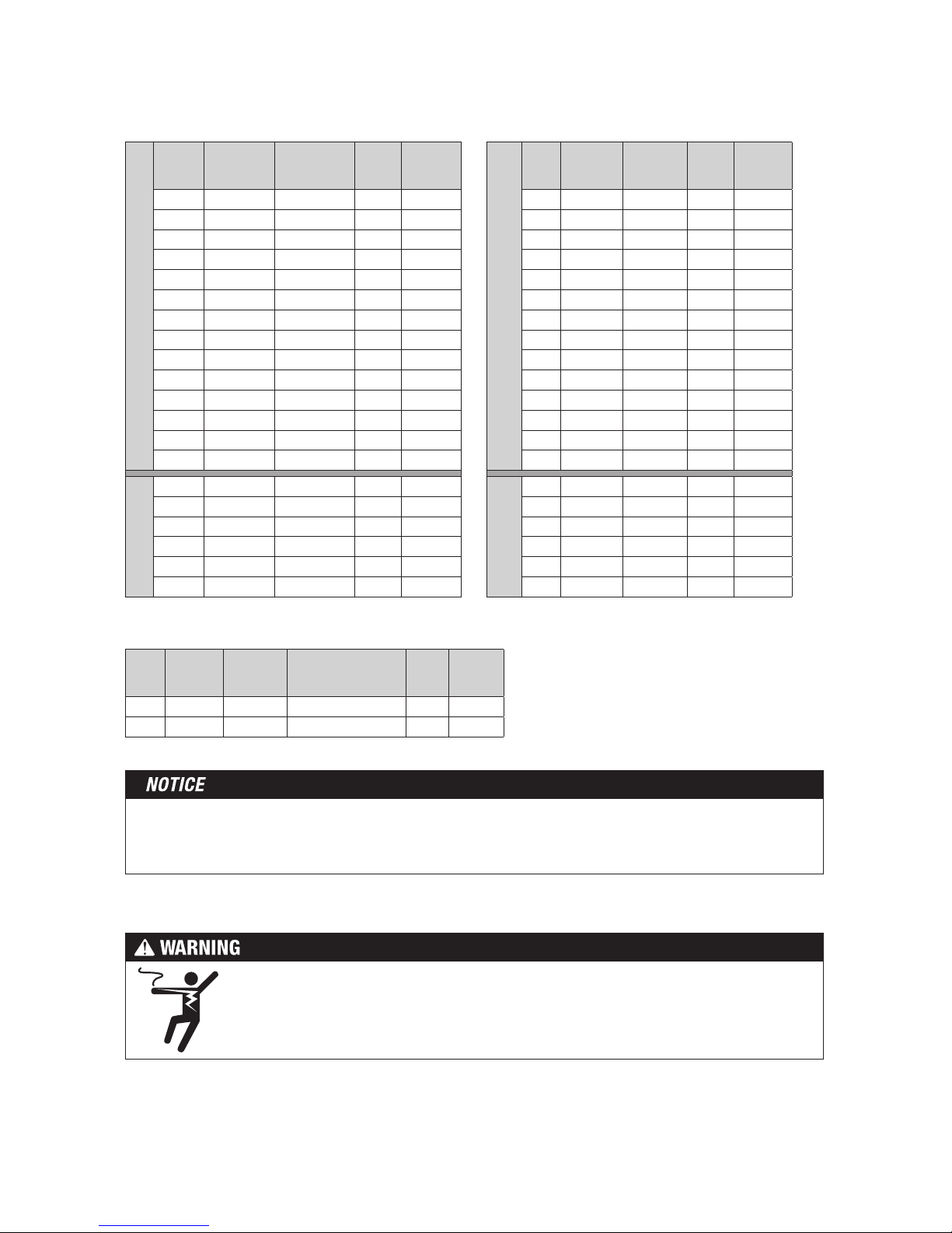
Circuit Breakers and Supply Wire
Mat(s) Supply Wire Breaker
VAC total amps (AWG)* qty type** rating
120 up to 12 amps 14 1SP 15 or 20 A
120 up to 15 amps 12 1SP 20 A
240 up to 12 amps 14 1DP 15 or 20 A
240 up to 15 amps 12 1DP 20 A
* Recommended only. Follow local codes for wire gauge size.
** SP= single-pole, DP=double-pole
Table 5
STEP 2.2:
Install Electrical Boxes
SunStat Thermostat:
Install an extra-deep electrical box for the SunStat thermostat. Follow the instructions included
with the SunStat for complete information on location and wiring. The thermostat must be
located at least 4 feet (1.2 meters) away from shower openings to avoid being exposed to
water or touched by a person while in the shower area.
SunStat Relay:
Install an extra-deep electrical box for any SunStat Relay(s). The SunStat Relay is used when
more than 15 amps must be controlled by one SunStat Thermostat. Follow the instructions
included with the SunStat Relay for complete information on location and wiring.
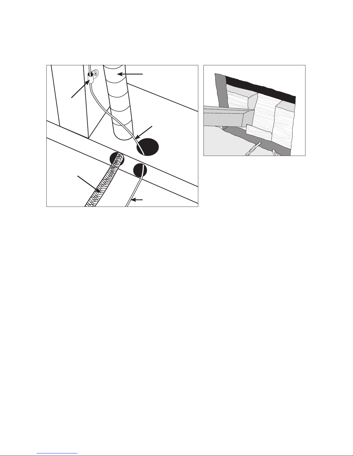
Junction Boxes:
If a mat is to be located so its Power lead is not long enough to reach the SunStat Control or
SunStat Relay directly, a junction box must be installed. Do not attempt to make a connection
to other wiring without a junction box. Use a standard junction box with a cover, mounting
it below the subfloor, in the attic, in the wall, or in another location easily accessible after all
coverings are complete. If the SunStat sensor wire is not long enough to reach the SunStat
Control directly, it may be extended. A junction box may be required by local code to make this
connection. Follow the installation instructions included with the SunStat Control for details.
For construction with an existing wall or where the wall is covered, cut the necessary openings
to mount the electrical boxes listed above. Wait to install the boxes until all wiring is fed into
these locations to make it easier to pull the wire.
It may be possible to tap into
an existing circuit as long as
there is adequate capacity for
the mat(s) and any additional ap-
pliance, such as a hair dryer or
vacuum cleaner. Avoid circuits
which have lighting, motors,
exhaust fans, or hot tub pumps
due to possible interference.

IOM-WR-TapeMat 1526 10 of 32
STEP 2.3:
Bottom Plate Work
Drill or chisel holes at the bottom plate as indicated. One hole is for routing the power lead
conduit and the other is for the thermostat sensor. These holes should be directly below the
electrical box(es).
Power lead
conduit
Wire
Clip
Power
lead
Sensor wire
Sensor wire
If going in to an existing wall, cut out
dry wall and chisel out bottom plate
to route wires to control.
STEP 2.4:
Install Power Lead Conduit and Thermostat Sensor
Power Lead Conduit:
The shielded power lead can be installed with or without electrical conduit (recommended
for added protection against nails or screws) depending on code requirements. Remove one
of the knock-outs in the electrical box to route the power lead. If electrical conduit is not
required by code, install a wire collar to secure the power leads where they enter the box. If
conduit is required by code, install 1/2" (minimum) conduit from the bottom plate up to the
electrical box. For multiple power leads (multiple mats) install 3/4" conduit.
Thermostat Sensor:
The SunStat Control sensor can be installed with or without electrical conduit depending on
code requirements. Conduit is recommended for added protection against nails or screws. Do
not place the sensor in the same conduit as the power leads to avoid possible interference.
Open a separate knock-out in the bottom of the thermostat box. Feed the sensor (and conduit,
if used) through the knock-out, down through the cut-out in the bottom plate, and out into the
floor where the heating mat will be installed. If the sensor wire needs to be secured to the wall
stud, wait until after the mat and sensor are completely installed on the floor.
STEP 2.5:
Rough-in Wiring:
Install appropriate 12 or 14 AWG electrical wire from the circuit breaker or branch circuit
source to the SunStat Control electrical box (and SunStat Relay box(es) if needed) following
all codes, see Table 5.
If SunStat Relay(s) are used, feed appropriate wire between the SunStat Relay(s) and the
SunStat Control. See SunStat Relay instructions for details of wire size and type.

11 of 32 © 2015 Watts Water Technologies
STEP 3.1:
Floor Cleaning
The floor must be completely swept of all debris including all nails, dirt, wood, and other
construction debris. Make absolutely sure there are no objects on the floor which might
damage the TapeMat wire.
Wet mop the floor at least twice to ensure there is no dirt or dust. This will allow proper
bonding of the mortar.
STEP 3.2:
Position the Power Leads
Carefully cut the tie binding the power lead coil. Do not nick the braid covering the power lead.
Place the mat on the floor to ensure the power lead will reach the control electrical box or
junction box location.
If the power lead will need to cross a long distance to reach the control location, it may be
possible to cut the mat mesh and pull loose the length of heating wire needed.
It is acceptable to run the power lead several feet in the floor area and embed in mortar, but
this may require making a shallow channel in the floor to ensure it lays flat with the rest of
the mat. See Step 3.8.
Make sure the power lead factory splice is to be completely flat and in the floor mortar,
not in the wall.
STEP 3.3:
Connect a LoudMouthTM
If a LoudMouth is being used, connect it to the power lead wires. Refer to the instructions
provided with the LoudMouth for details and proper connections.
Phase 3 - Mat Installation
Do not cut the heating wire to make it fit the area. Doing so will cause dangerous overheating
and will void the warranty.
Test fit the mat by rolling it out, flipping it on itself as needed.
Make sure it fits before cutting the mesh.

IOM-WR-TapeMat 1526 12 of 32
STEP 3.4
Test Fit the Mat
Roll out the mat, flipping it as needed to cover the intended area. This is very important to
ensure proper fit before proceeding. If there is too much mat for the area it cannot be cut
shorter and heating wire cannot be routed into a wall, under baseboards, or other similar areas.
All heating wire must be embedded in the floor mortar.
STEP 3.5
Shape the Mat
If the mat must be shaped to fit the floor area, see Table 6 for technique examples and see
the Appendix for additional layouts, techniques, and Cautions.
Install the mat approximately 4"–6" away from walls, showers, tubs, drains, etc. and 6" from a
toilet wax ring. It may be installed closer to walls if necessary, but make sure the heating wire
will not be located underneath finish trim. Install in-line with vanity and counter areas. Install
roughly 20" from back wall in toilet area.
Table 6
Mat Turns and “Fill-in” Techniques
This table contains some of the common turns and techniques used to layout around corners,
angles, and built-ins.
180° or Back-to-Back Turn. 90° or Flip Turn.
Carefully cut the orange mesh to make turns. Never cut, nick, or otherwise damage the
heating wire.
Cut mat
Flip mat
over
Rotate
Cut mat
DO NOT leave gaps between the mats. The heat will conduct only about 1-1/2" from the
heating wire. Mat should be installed continuously across the floor. Never install mats in a
fashion causing the heating wires to be any closer than 2" from each other or to overlap.

13 of 32 © 2015 Watts Water Technologies
Fill-in Technique.Roll-over Turn.
Mat mesh
removed
Use hot glue to
attach wire to the oor.
Cut mat
Roll
over
Installing in front of cabinets and toilets:
Install mat right up to the face of the cabinet
as shown above.
Mat can be installed under tile to within
6" from the wax ring, and can slightly
underlay the foot of the toilet if need be
(approximately 20" from wall).
ShowerMat
power lead
Factory splice embedded in mortar outside of shower

IOM-WR-TapeMat 1526 14 of 32
STEP 3.7
Use a digital multi-meter to measure the
resistance between the conductors of the
power leads again. Record these resistances in
Table 4 under “After mat is secured in place”.
STEP 3.8
Feed the power leads through the conduit
to the control electrical box, leaving at least
6"-8" of free power lead. Chisel a slot in the
floor to recess the factory splice level with the
heating wire. Secure the factory splice with hot
glue so it cannot be pulled into the conduit.
Chisel a path for the power
lead and factory splice.
Use hot glue to secure to the floor.
Place a metal nail plate over the transition point
to protect the power lead and sensor wire.
Power Lead/
Heating Wire
Connection
Nail
Plate
Floor
Sensor
Wire
Securing the mat as flat as possible will help
make a smooth surface for spreading mortar.
DO NOT staple or apply tape over the heating
wire. Damage can result.
DO NOT use nails, duct tape, other types of
tape, or other unapproved fasteners
to hold the heating wire or mesh
in place. Damage can result.
If the mat comes with double-sided tape
already attached, remove the liner along one
edge and press the tape down. Remove the
liner along the other edge and press the tape
down, pulling lightly on the mat to keep it flat.
Ensure all edges of the mat are secured to
the floor using double-sided tape or hot glue.
Secure as needed across the middle of the
mat to ensure the it stays flat during floor
mortar application later. Do not use staples
or anything else that will cause damage to
any waterproofing membrane.
STEP 3.6
Secure the Mat to the Floor
Lay the mat down flat. Ensure it fits well and
has no folds or large ripples.
It may be necessary to use a metal nail plate
to protect the power lead and sensor wire
as they transition into the wall. This will help
prevent nail penetrations from drywall and
baseboards trim.

15 of 32 © 2015 Watts Water Technologies
STEP 3.9
Feed the sensor wire to the SunStat
thermostat electrical box leaving at least
6"-8" of free lead length in the box. Weave
the sensor at least 1' into the mat area,
halfway between the heating wires, and
secure it using hot glue. Do not cross
the heating wires. It may be necessary
to chisel a small section of the subfloor
to accommodate the sensor, depending
on the thin-set thickness being used.
Tape
Top-Down view of Mat and the sensor entering wall.
Heating Wire
Sensor
Conduit
Power Lead
Factory Splice
(in thin-set, not
in conduit)

IOM-WR-TapeMat 1526 16 of 32
Locate power lead and factory connection to
heating wire at least 1’ outside the shower area.
Acceptance of this application must be verified by the local inspector or authority having
jurisdiction (AHJ).
STEP 3.10:
Shower Application
1. Refer to diagrams in the Appendix, especially pages 26 & 27.
2. Never install TapeMat or ShowerMat in shower walls (or any other wall).
3. Never make a field splice to mats installed in a shower.
4.
It is recommended that a dedicated mat be installed in the shower area, separate from
the mat in the rest of the floor. In case there is ever a problem with the shower installation,
this mat could be disconnected without loss of heat to the rest of the floor.
5.
Use the double-sided tape or hot-glue to secure the ShowerMat. Do not use staples or
anything that will damage any waterproofing membrane.
6.
If the heating wire must enter the shower area over a curb, secure the wire at the edges
in an "s-shaped" curve to ensure the wire is not bent sharply or pinched when surface
coverings are installed. Do not damage any waterproofing components, and do not run
the heating wire through a non-masonry curb, causing it to overheat.
7. Embed mats in mortar and install only under tile, stone, brick, or other masonry surface,
per this instruction manual.
8.
Never begin the mat in a shower. The connection between the power lead and the heating
wire must be fully embedded in mortar and located at least 1' (304.8 mm) away from shower
openings and other areas normally exposed to water.
9. Mat controls must be located at least 4' away from shower openings. Controls cannot be
exposed to water or touched by a person while in the shower area.
10. If covering a bench seat in the shower, carefully trim away mesh to release some heating
wire. Use hot glue to secure a single run of wire up the side of the bench riser. Fill in the
seat with mat. Then secure a single run of wire down the riser if needed. Use an "s-shaped
curve to avoid sharp bends at corners and help the wire to lay flat.
11. All grout seams should be sealed after the mortar and grout has completely cured.
Take photographs of the mat installation. This can be very useful later during remodel
work to help avoid possible wire damage. Keep the photos with this installation manual
and provide to end user upon completion.
Heating Wire
Factory Splice
Shower
Curb
Tile
Thin-set
Mortar
Avoid sharp
bends in
heating wire

17 of 32 © 2015 Watts Water Technologies
Phase 4 - Floor Coverings / General Recommendations
Do not use solvent based adhesives or pre-mix mortars because they are not as heat
resistant and do not conduct heat well.
Please note, this installation manual is not a structural or a floor covering installation manual
and is intended only for general guidance as it applies to the TapeMat product.
It is recommended to consult with professional flooring installers to make sure proper
materials are used and proper installation techniques are followed.
Make sure nails, screws, or other fasteners do not penetrate the floor in the TapeMat area.
The wire can easily be damaged by fasteners penetrating the floor.
When installing tile or stone, the Tile Council of North America (TCNA) guidelines, National Tile
Contractors Association (NTCA), or ANSI specifications should be followed as a minimum standard.
A polymer-modified thin-set cement-based mortar and grout is recommended instead of
water-based multi-purpose materials when installing a radiant product.
Select the proper size trowel for the installation of tile or stone. We recommend a minimum
3/8" x 1/4" trowel. This trowel works well for most ceramic tile. A thicker thin-set can be used
if required. Select the thin-set thickness in accordance with the floor covering requirements.
For additional information on tile installation, please contact TCNA at 864-646-8453 or visit
their web site at www.tileusa.com, or contact NTCA at 601-939-2071 or see their web site at
www.tile-assn.com
When installing floor coverings other than tile or stone, follow industry and/or manufacturer’s
recommendations. Ensure the mat is first covered with a layer of self-leveling cement based
mortar, letting it cure fully before applying any surface underlayment, floating wood or laminate
flooring, carpet, etc. The combined R-values of all floor coverings over the mat should not
exceed R-3. Higher R-values will diminish performance. Consult the floor covering manufacturer
to verify compatibility with radiant electric heat.
All floor coverings must be in direct contact with the cement-based mortar encasing the mat.
Do not elevate the floor above the mortar mass. Do not install 2" x 4" wooden nailers (sleepers)
on top of a slab for the purpose of attaching hardwood. Any air gap between the heating mat
and the finished floor covering will drastically reduce the overall output of the heated floor.
Care should be taken when laying area rugs, throw rugs, and other surface products on the
floor. Most products are okay to use, but if in doubt, consult the product manufacturer for
compatibility. Do not use rubber backed products that may degrade or very heavy rugs that
will trap heat. Be careful not to place a rug over the area where the sensor tip was placed,
causing false thermostat readings.
When placing furniture make sure an air clearance of at least 1-1/2" is available. Furniture able
to trap heat can damage the heating system, the flooring, and the furniture over time.
Use a digital multi-meter to measure the resistance between the conductors of the
power leads again. Record these resistances in Table 4 under “After floor coverings
are installed”.

IOM-WR-TapeMat 1526 18 of 32
Type of Construction
Mortar Applications:
Thin-set and thick-set (self-leveling) mortar applications are illustrated below and to the right.
a.
If a backer board or plywood sheeting is used to strengthen the floor, or if the mat will
be placed directly onto the slab, install TapeMat in the thin-set mortar bond coat above
these materials.
b. If a thicker mortar bed, or self-leveling concrete, is used to strengthen the floor, TapeMat
can be installed in either the mortar bed (dry-set) or in the mortar bond coat directly below
the tile or stone.
TapeMat is generally installed above the self-leveling mortar in a thin-set bond coat. Use plastic
lath instead of the typical metal lath when installing in a self-leveling layer.
Self-leveling Mortar Applications:
These are appropriate applications if installing engineered wood, vinyl, laminate, or carpet
floor coverings. Attach the TapeMat to the subfloor or slab, then pour self-leveling mortar
1/4” to 1/2” thick according to manufacturer’s specifications. Fully embed the heating wire
and splices so that no portion of these show. Install floor covering after the mortar has cured.
Special Precautions
Isolation Membrane: Install the TapeMat above the membrane, whenever possible, unless
recommended otherwise by the membrane manufacturer.
Insulation: Insulation dramatically enhances the performance and efficiency of floor-warming
systems. Do not install rigid insulation directly above or below backer board or mortar.
Mosaic Tile: When installing mosaic tile, it is recommended to apply a two-step process.
First, embed the Mat in a thin self-level mortar bed (1/4"–3/8"), then thin-set the mosaic tile
according to typical practice.
Expansion Joints: Do not install heating mats through an expansion joint. Install mats right
up to the joint, if necessary, but not through the joint.
DOUBLEPLYWOOD OVER FRAME FLOOR
Tile/stone or
laminate flooring
TapeMat
Plywood
Main Plywood Subfloor
Latex-Portland cement
mortar bond coat
Insulation
(per International Residential
Code, Chapter 11)
Never bang a trowel on the Heating Wire to remove excess mortar from the trowel. This
could damage the heating wire.

19 of 32 © 2015 Watts Water Technologies
Tile/stone or
laminate flooring
Tile/stone or
laminate flooring
Concrete slab with
rewire or rebar
Crack isolation membrane
/Insulating barrier
TapeMat
Thin-set or self-
leveling mortar bed
Insulation
(per International Residential
Code, Chapter 11)
Insulation
(per International Residential
Code, Chapter 11)
Cement backerboard,
thick-set, or self-
leveling mortar bed
TapeMat
Thin-set
THINSET OVER SLAB ON GRADE
CEMENT BACKERBOARD OVER FRAME FLOOR

IOM-WR-TapeMat 1526 20 of 32
Phase 5 - Control Installation
STEP 5.1:
Install the Controls
If it has not already been done, install an electrical box for the SunStat thermostat and SunStat
Relay. See Step 2.2 for details.
STEP 5.2
Read and follow the instructions included with the SunStat thermostat and SunStat Relay for
complete connection instructions, requirements, and mounting.
STEP 5.3
Make any final connections to the circuit breaker or branch circuit source.
Most laminate and wood floor manufacturers specify their flooring should not be subjected to
temperatures over 82° to 84°F (27° to 28°C). Check with the flooring dealer or manufacturer
and set the thermostat Floor Limit temperature appropriately.
Refer to the installation sheets provided with the controls for proper setting. The system
should now operate as designed. Please leave this instruction manual, SunStat Control
instructions, and copies of photos of the installed heating system with the end user.
CKT#
CKT#
CKT#
Radiant Floor Heating Mat
Warning - Risk of electric shock
Electric wiring and heating panels
contained below the floor. Do not
penetrate floor with nails, screws,
or similar devices
Nappe de chauffage de sol
Avertissement: Rique de choc électrique
Câblage électrique et nappes de chauffage
dans le sol. Ne pas enfoncer de clous, vis
ou autes éléments d’assemblage similaires.
Tapete radiante para calefaccion de pisos
Precaución: Riesgo de electrocución
El piso contiene cables eléctricos y paneles
calafactores. No insertar clavos, tornillos ni
dispositivos similares.
STEP 5.4
System Start Up
After all controls are installed, do not energize the system, except to briefly test operation of
all components (no longer than 10 minutes). Do not put the system into full operation until
the tile or flooring installer verifies all cement materials are fully cured (typically two to
four weeks). See mortar manufacturer’s instructions for recommended curing time.
Place this warning label (provided with
the product) on the electrical panel and
indicate the circuit breaker number that
supplies the radiant heating. Also, place
the label indicating “Radiant Floor Heating”
on the control.
Make sure 120 VAC is supplied to 120 VAC mats and 240 VAC is supplied to 240 VAC mats.
Otherwise, dangerous overheating and possible fire hazard can result.
This manual suits for next models
2
Table of contents
Other suntouch Floor Heating System manuals