Momento CAR-P series User manual

INSTRUCTION MANUAL
INS481-201411-01
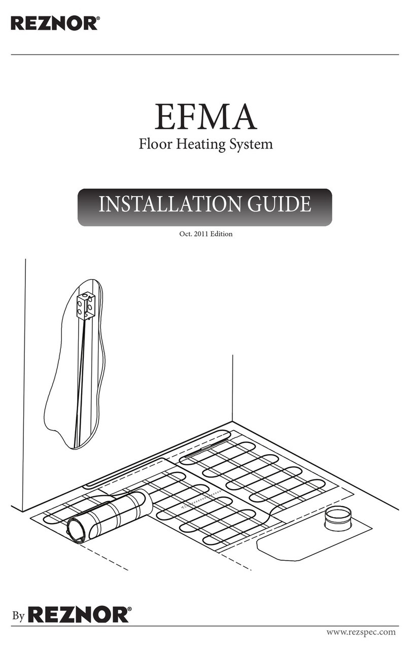
CAR-P Series
Floor Heating Cable
for Installation with Strapping

Warranty
Subject to provisions stipulated in the Consumer Protection Act’s legal requirements respecting the quality and
durability of goods: Momento guarantees its CAR-P series heating cables and its heated floor systems for
a period of 25 years from the date of purchase against any manufacturing defect or malfunction.
Limitations and exclusions
The above mentioned guarantees are limited to the reimbursement of the original purchase cost or replacement
of the heating cables (hereinafter called "equipment") excluding any other part and also excluding any cost or any
expense relating to connection, removal or installation of aforesaid equipment, including all workmanship costs.
The buyer may choose between the reimbursement of the original purchase cost and the replacement of defec-
tive equipment, subject to the aforementioned restrictions. This warranty is provided to the original buyer
of the equipment as well as subsequent owners of the building where the equipment was installed.
Warranty terms
The above mentioned warranties are subject to the following conditions:
i. The buyer must provide the original purchase invoice for the defective equipment, to Momento or to one of
their authorized dealer.
ii. The buyer must report promptly in writing to Momento any malfunction of equipment covered by the present
warranties, in a reasonable time frame, from the time the malfunction occurred or the malfunction was
brought to their knowledge thereby enabling Momento’s representatives enough time to verify the defective
equipment, if need be.
iii. Equipment covered under the present warranties must be installed in compliance with Momento’s instructions.
iv. Equipment covered under the present warranties must be used under normal conditions of use and be
maintained on a regular basis from the date of purchase.
Name and address of the person providing the present warranties:
Momento
2713, boul. Louis XIV
Québec (Québec) G1C 5S9 CANADA
Telephone: 418-663-7878 • 1 866 930-7878
Fax: 418-663-7267
www.momentoconfort.com

Table of contents
1 Warnings and cautions......................................................................................................................................................................................2
2 Product specifications and details ..........................................................................................................................................................3
3 Selection of floor heating system ............................................................................................................................................................4
4 Critical information ..............................................................................................................................................................................................5
5 Selection of floor covering material.......................................................................................................................................................7
6 Thermal insulation................................................................................................................................................................................................8
7 Installation instructions ...................................................................................................................................................................................9
7.1 Planning work..............................................................................................................................................................9
7.2 Room layout and corresponding floor heating system product............................................................ 10
7.3 Preparing the subfloor........................................................................................................................................... 10
7.4 Marking the floor ..................................................................................................................................................... 12
7.5 Installing the floor heating system.................................................................................................................... 13
7.6 Installing the temperature sensor ..................................................................................................................... 16
7.7 Applying self-levelling cement........................................................................................................................... 17
7.8 Connecting the system.......................................................................................................................................... 18
7.9 Measuring resistance and measures table ..................................................................................................... 19
7.10 Using the floor heating system........................................................................................................................... 19
8 Temperature controller..................................................................................................................................................................................20
9 Pre-installation preparations ...................................................................................................................................................................21
9.1 Installation tips ......................................................................................................................................................... 21
9.2 Floor covering tips................................................................................................................................................... 21
10 Operating tips ........................................................................................................................................................................................................22
11 Locating a fault......................................................................................................................................................................................................22
12 Control card..............................................................................................................................................................................................................24
Please read through these instructions carefully
before you begin installing & check that
you are aware of all the components required.
CAUTION!

2
1
Warnings and cautions
Risks of electrical shocks and fire
For safe installation and efficient performance of this system, read the instruction
manual thoroughly and keep it handy.
• Where applicable, installation must meet requirements of the following codes:
- Canadian Electrical Code (CSA C22.1 Part 1);
- National Electrical Code (NFPA 70);
- Any other applicable local and/or national code.
• Where required by law, this product must be installed by a qualied individual.
• To prevent any possibility of electrical shocks, the power supply must be turned o
before handling the heating cables.
• A GROUND FAULT PROTECTION DEVICE MUST BE USED WITH THIS PRODUCT,
UNLESS EXEMPTED BY ELECTRICAL CODE IN FORCE.
• This heating cables must be used for indoor applications only.
• This heating cables must be installed and fully embedded in cement or an
equivalent binder (cement glue, ceramic glue or self-levelling cement).
SAVE THESE INSTRUCTIONS

3
Product specifications and details
The floor heating system is designed exclusively for interior floor heating. The system is not designed for snow
melting or any other outdoor uses; it is mainly designed to complement a building’s primary heating source by
serving as a secondary (floor warming) or primary room heat source (radiant floor heating);
This heating system, is a cable made of a twin conductor with a 10 feet cold lead.
The heating cable consists of a resistance-heating element insulated with Fluoropolymer (FP) having high
dielectric strength and high temperature withstand ability, which makes the heating cable safe. A metallic
sheath is provided to give additional mechanical strength and provide ground path. A final outer jacket of PVC
or Fluoropolymer is given to make it sturdier and provide corrosion protection. The hot and cold junction
is uniquely designed to make it fool proof.
These are available in a wide range of capacities and length to suit your requirements.
2

4
3
Selection of floor heating system
Selection of floor heating system will depend on the application.
As a general guideline, we recommend installation at a maximum of 12 watts per Sq.ft. for heating and comfort
applications.
Depending on the claimed result, the cable system can also be used in 9 watts per Sq.ft. applications. To ensure
optimal heating results, please contact a qualifed individual.
Wet areas (in locations subject to saturation with water) like showers, saunas and steam rooms, bathrooms, etc:
12 watts per Sq.ft. The UL listing for this product does not cover use in wet location in the United States.
Please note the above-indicated values are meant as a general guide, actual requirement will depend on insu-
lation levels, floor construction, type of floor coverings, ambient temperature, movement of the people etc.
Note: The floor heating system can be installed under a shower floor only if the floor is ceramic or natural stone.
A waterproof membrane must be used to maintain the heating cables in a dry environment. The manufacturer recom-
mends using a separate cable for the shower area. The UL listing for this product does not cover use in wet location in
the United States.

5
4
Critical information
1Heating cable must not touch, crossover or overlap itself at any point. (Please use strapping to avoid
bunching or crossover of cable). This could cause the cable to overheat.
2Heating cable cannot be cut.
3The heating cable length cannot be altered in any circumstances. This may cause over heating resulting in
damage to the cable.
4Take precautions to avoid damage to the heating cable during installation, due to dropping sharp objects
or stepping or careless pouring of concrete or banging the trowel on the heating cable while applying cement
mortar for tiling/flooring. In case of remodeling of floors, make sure that old mats/cables are removed before
you lay new heating cables.
5Heating cables should be separated from other heat sources such as floor luminaries and chimneys.
6Do not install the heating cable below -15 °C (5 °F) ambient temperature.
7Minimum bending radius of the under cable while laying shall not be less than 1 inch (25 mm).
8If Thermal Insulation Boards of adequate thickness is used, please ensure the item has typical R Value
of 0.027 or less.
9The cold lead, normally 10 feet long, can be cut/extended to suit the location of the electrical power
connection box.
10 Floor thermostat sensor location shall be centered between two adjacent runs of heating cable.
Do not locate oor thermostat sensor closer than 1 inch to heating cable or allow to overlap any other
cable.
11 Maximum limit of the temperature setting on the thermostat should not exceed 30 °C (86 °F).
12 Check the main voltage and wattage of the heating cable as per the selection made. These are marked
on the label of the product.
13 Keep the power leads conduit separate from the sensor cable conduit.
14 It is highly recommended to connect the Cablecheck during the installation to warn about accidental damage
to the heating cable or lead wires.
15 Incase GFCI trips during normal operation, and cannot be reset, there is likely a fault in the cable. No attempt
should be made to re-energize the heating cable. GFCI must not be bypassed in any circumstances.
Consult a qualified individual.
16 Do not install the heating cable under permanent fixtures.
17 Allow sufficient drying or curing period of the sub floor and finished floor before and after installing the
heating cable.
18 Indicate which branch circuits supply the power to the heating cable and retain the UL labels for each heating
cable in a convenient location, i.e. taped to the circuit breaker box, for reference by the electrical inspector
or home owner. Leave one UL label attached to the heating cable. Attach warning label in convenient location
to show the room location where heating cable is installed.
19 Use only listed conduit, fittings, and or other components.
20 Heating cables shall not extend beyond the room or area in which they originate.
21 This heating cable shall be installed only by qualified individual who are familiar with the construction and
operation of the heating cable and the risks involved.
22 The installation of the heating cable shall be in accordance with the manufacturer’s instructions and local
national codes.
23 The manufacturer recommends using a separate cable for the shower area. The UL listing for this product does
not cover use in wet location in the United States.
6
24 Required distances and clearances
• Minimum3"(76mm)betweenheatingcables;
• 3"(7.6cm)fromanyexteriorwall,interiorwall,drain,oranyxedobstacleyouneedtogoaround.
Note: 10" (25.4 cm) from a toilet drain with a wax ring seal;
• 3"(7.6cm)fromanyxedunit(e.g.,vanitysink,shower,refrigerator);
• 8"(20cm)fromanyheatingapplianceaxedtoorincontactwiththeoor;
• 2"(5cm)betweentheoorsurfaceandthefurnituretoallowairtocirculatefreely;
• 10'(3m):maximumlengthofafreecableinastraightline.
25 The system is only one step in the floor construction process. Each trade is responsible for the quality of its
work and must ensure that the work performed by the previous tradesman has been duly completed
according to code. All tradesmen are engaged in the installation process and share joint responsibility for it.
26 Perform all six (6) insulation and resistance test steps required during installation:
1 Before breaking the security seal and opening the product.
Note: Once the seal is broken, you are then in charge of the cable integrity throughout the entire installation
process. Be sure to follow instructions and observe all precautionary measures.
2 After the installation of the heating cable.
3 Before embedding the heating cable.
4 After embedding the heating cable.
5 After the final installation of flooring.
6 Before connecting the heating cable system.
- Enter results in the measurement table found in the envelope;
- Affix the measurement table to the electrical panel, once completed.
Note: The UL Listing for this product covers use in wet locations for CANADA only. Wet location installation in United
States shall be in accordance with the National Electric Code, (NFPA 70) and any other applicable jurisdictional code
and final acceptance is to be made by the Authority Having Jurisdiction (AHJ).
NEVER install a heating cable under an interior wall or any fixed unit,
a closet or in any other location where air cannot circulate freely over
the floor surface. Always maintain the following minimum clearance:
“Risk of electric shock and fire”.
“Damage to supply conductor insulation may occur if conductors
are routed less than 3 inches (76 mm) from this heating product.
Refer to installation instructions for recommended means of
routing supply conductors”.
CAUTION!
N
e
v
e
r
c
u
t
t
h
e
h
e
a
t
i
n
g
c
a
b
l
e
N
e
v
e
r
s
t
a
p
l
e
t
h
e
h
e
a
t
i
n
g
c
a
b
l
e
t
o
t
h
e
s
u
b
f
l
o
o
r
N
e
v
e
r
s
t
a
p
l
e
t
h
e
f
l
o
o
r
s
e
n
s
o
r
t
o
t
h
e
s
u
b
f
l
o
o
r
D
o
n
o
t
l
a
y
h
e
a
v
y
i
t
e
m
s
o
n
t
h
e
c
a
b
l
e
W
ARNING!

7
Selection of floor covering material
The type and thickness of floor covering materials used with this product must not exceed a thermal insulation
“R” value of 1 (RSI = 0.123).
Typical floor covering Thermal resistance
R RSI
Vinyl tiles 0.20 0.035
Linoleum 0.22 0.039
Ceramic 0.25 0.044
Low-pile carpet 1.0 0.123
Natural stone (Granite, limestone, marble, sandstone) 1” thick 0.38-0.114
Plywood 0.5” thick 0.63
Parquet flooring 0.70 0.123
Floating floor 10 mm to 16 mm (3/8” to 5/8”) (Laminate) 0.70 0.123
Wood on lathes (strapping)*2.10 0.368
*The floor covering highlighted in grey is prohibited.
5
For engineered wood floorings, laminated hardwood flooring,
vinyl coverings, and linoleum glued to a concrete surface,
consult your floor covering manufacturer to ensure they are
compatible with floor heating systems.
IMPORT
ANT!

8
6
Thermal insulation
The insulation levels of a floor will affect both the performance & running costs of floor heating system.
The thermal insulation reflects the heat upwards into the floor tile instead of allowing heat to penetrate into the
subfloor and keeps the floor warmer for longer time. While installing the floor heating system, user should install
adequate thermal insulation below it. In cases where the floor heating system is being installed over large areas,
insulation boards will greatly reduce warm-up times & running costs.
When floor heating systems are installed on a concrete slab, we strongly recommend adding a layer of insulation
to the slab prior to installing the heating cables. Adding insulation on top of the concrete slab or board, and
beneath any floor heating system will allow a greater percentage of heat generated to transfer to the flooring
surface.
The heating cable system is approved for the following types of installation:
• Onasuboor
Important: The subfloor material in contact with the heating cable must be able to withstand
a temperature of at least 90 °C (194 °F).

9
7
Installation instructions
Onceyouhavechosentheareatobeheated,measuretheareainsq.feet(donotincludetheareatakenupby
fixed objects such as appliances/baths/kitchen units, etc.) and required watt density for your room. Now calculate
total required output by multiplying area x watt density required for the room. Choose nearest suitable wattage
cable from the available range. When calculated size required is between two sizes of offered cables, select the
smallest of the two.
Cable rating Density and distance between cable
3 inches 4 inches 5 inches 6 inches
9.84 w/m
(3 w/ft.) 12 w/sq.ft. 9 w/sq.ft. 7.5 w/sq.ft. 6 w/sq.ft.
Each cable’s length is listed in the product selection guide; combine the cable lengths if more than one is being
used. It is recommended that you cut out a measuring template out of cardboard representing the distance
between the cable. You will then be able to place this template next to a cable in order to determine where the
next run should be placed.
We recommand the installation of the cable at a spacing of 3 or 4 inches for an uniform floor temperature.
7.1 Planning work
Materials provided by the manufacturer
• Heatingcable
• Installationstrappings
• Installationinstructions
• Measurementtablelabel
• Floortemperaturesensor
Material required
• TemperaturecontrolwithGFCI(availableatthemanufacturer)
• Cablechecktester(availableatthemanufacturer)
• Stapler
• Screws
• Protectiveglasses
• Measuringtape
• Broom
• Feltmarker
• Tape
• Hotgluegun
• Woodchisel
• Hammer
• Multimeterandmegohmeter
• Electriciantools
• Electricaltape
For installation over a concrete slab, add the following:
• Concretechisel
• Drillingmachine
• Percussiondrillforconcrete

10
7.2 Room layout and corresponding oor heating system product
• Createaroomlayoutplantoscale(formaximumaccuracy,usethemanufacturerformdesigned
for this purpose);
• Identifyallstationaryelements(toilet,bath,shower,counters,drawers,andpermanentfurnishings)
and never install the heating cable under these stationary elements (Figure 1);
• Determinethermostatortemperaturecontrollocation;
• Noteroomdimensions;
• Determinetheelectriccable(coldlead)locationthatwillbeconnectedtotheheatingcontrol;
• Calculatetheheatingareainsquaremeters(sq.m.)[squarefeet(sq.ft.)];
7.3 Preparing the subfloor
• Cleanandremoveanydebris,orprotrudingobjectsthatcoulddamagetheheatingcable;
• Suboorcracksmustbelledwithpolyesterwoodller(onlyforself-leveller);
• Thesuboormustbesolidlyfastenedinplacetopreventmovement;
• Theapplicationofaoorlevellingproductisrecommendedtopreventfuturedamagetotheceramiccaused
by subfloor movement;
• Forconcretesuboors,applyasurfacesealerthatiscompatiblewithelectricalheatingsystemsinaccordance
with the cement glue manufacturer’s instructions. Completely coat the surface;
• Letdrybeforeinstallingoorheatingsystem(refertothesealer'sinstructionsfordryingtime).
Liaison froide
Sonde de
température
10'
8'
Need help to optimize your work plan? Contact our technical support.
Clearly indicate all dimensions. A minimum of one horizontal and
one vertical dimensions are necessary to validate the scale.
Figure 1

11
heating cable
junction
cold lead
channel
strapping
cold lead
plywood
or concrete slab
strapping
heating cable
self-levelling
cement
cement glue
floor covering
Figure 2
Figure 3

12
7.4 Marking the oor
• Ontheoorofanemptyroom(underconstructionormajorrenovations),drawthelocationofstationary
elements (toilet, bath, shower, counters, drawers, permanent furnishings) that will be installed later. These
marks will outline the heating area to ensure the heating cable system is not placed under these stationary
elements;
• Theoortemperaturesensormustbecenteredbetweentwoparallelheatingcables.Theideallocationis
one where it is likely to be away from stationary objects and sheltered from outside influences (sunlight)
that could skew floor temperature readings. For maximum comfort, the area above the sensor must be free
of obstruction.
Figure 4
Figure 5

13
7.5 Installing the floor heating system
heating cable junction
channel
cold lead
Tape, hot glue gun, stapler
1) First insulation and resistance test.
Before breaking the security seal and opening the product, measure
thecable'selectricalandinsulationresistanceandrecordthereadings
on line 1) Before breaking seal.
Figure 6

14
Cable strappings’ installation:
• Thestrappingsarexedontheoorwithstaplesorscrews(whentheoorismadeofplywoodorwood)
or with a hot glue gun;
• Thestrappingsmustfollowtheoutlinedrawnontheroomlayout(section7.2);
• Ifthelacingdistancebetweentwostrappingsisover0.625m(2ft.),itisnecessarytoplaceanintermediate
strapping to maintain the cable in position during the pouring of self-leveller, this strapping is installed at the
end, after the lacing of the cable;
• Thecablecanbeinstalledundertheceramictileofashowerorotherwetsurfaces,thestrappingsandthe
heating cable must be glued under the wateproofing membrane and not stapled, staples could damage
the waterproofing membrane (the UL listing for this product does not cover use in wet locations in the
United States).
on plywood
on concrete slab
Figure 7

15
Installation of the heating cable
• Setthecableneartheconnectionboxandregularlylacetheheatingwirerespectingthedistancebetweenthe
sections; 76 mm (3”) minimum;
• Donotbendthecableat90°whensettingitinthestrappinghooks;leavea25mm(1“)radius.Thisradius
comes naturally; the cable must not be forced to have a tight bend;
• Atagislocatedat50%ofthecablelength.Duringinstallationoftheproduct,verifythecablehalftagto
compare with your cable layout planification. Adjust pattern with the result to cover the surface. If the cable is
too long, use the buffer zone to spend the remaining cable. Never shorten the heating cable. The heating cable
must not be shortened, neither cut;
• Alwaysstartthecableatleast76mm(3”)fromthewalls;
• Itisimportantnottosubjecttheheatingcabletoanymechanicalstrain
(stretching,bendingradiusunder25mm[1”],scoring).
• Avoidwalkingonthecables.
N
e
v
e
r
c
u
t
t
h
e
h
e
a
t
i
n
g
c
a
b
l
e
N
e
v
e
r
s
t
a
p
l
e
t
h
e
h
e
a
t
i
n
g
c
a
b
l
e
t
o
t
h
e
s
u
b
f
l
o
o
r
N
e
v
e
r
s
t
a
p
l
e
t
h
e
f
l
o
o
r
s
e
n
s
o
r
t
o
t
h
e
s
u
b
f
l
o
o
r
D
o
n
o
t
l
a
y
h
e
a
v
y
i
t
e
m
s
o
n
t
h
e
c
a
b
l
e
2) Second insulation and resistance test.
After the installation of the heating cable, measure the cable’s
electrical and insulation resistance and record the readings on line
2) After cable installation.
IMPORT
ANT!
Figure 8

16
7.6 Installing the temperature sensor
• Tominimizeoorheight,chisela10mmx10mmx250mm(3/8”x3/8”x10”)channelinthesuboorto
receive the floor sensor. The junction has an insulation sheath and a slightly larger diameter than the heating
cable.
• Gluethesensortothesuboor(Figure9).Thesensormustbesolidlyfastenedtothesuboortoensureitstays
in place when the cement or an equivalent binder (cement glue, ceramic glue, self-levelling cement) is applied.
Hot glue gun, hammer, wood chisel or concrete chisel
channel
temperature
sensor
The sensor must be embedded in cement or an equivalent binder
(cement glue, ceramic glue, self-levelling cement).
IMPORT
ANT!
Figure 9

17
7.7 Applying self-levelling cement
• Consultthemanufacturer’sinstructionforthetypeofoorcovering(ceramic,linoleum,orother).
See Section 5;
• Completelyembedtheheatingcableinself-levellingcement(Figure10).ItiscrucialthattheENTIREheating
cablebeembedded.Nopartoftheheatingcablemustbeexposed.(Asmallpart[top]ofthe
heatingcablemaybeexposedatthesurfaceoftheself-levellingcementONLYIFaceramicglueisused
afterward AND embeds that part);
• Levelthesuboorwithself-levellingcementorcoverthecablewithalayerofcementgluewheninstalling
the stones or ceramics.
Do not turn on the floor heating system before the cement has
completely dried. Follow manufacturer recommandations (may
take up to 30 days, depending on the product).
3) Third insulation and resistance test
Before embedding the heating cable in self-levelling, measure the
cable’s electrical and insulation resistance and record the readings
on line 3) Before embedding cable.
4) Forth insulation and resistance test.
Oncethecementorbinderhasbeenapplied,measurethecable’s
electrical resistance and record the readings on line 4) After
embedding cable.
IMPORT
ANT!
Figure 10

18
7.8 Connecting the system
Cold lead
240V/208V connection: 120V connection:
Line 1 – Black Sheath Line – Black Sheath
Line 2 – Red Sheath Neutral – Yellow Sheath
Bare wire – Ground Bare wire – Ground
Final view
The system must be connected by a master electrician.
6) Fifth insulation and resistance test.
Before wiring system, measure the cable’s electrical resistance
and record the readings on line 6) Before wiring system.
Self-levelling
cement
cement glue
floor
covering
IMPORT
ANT!
Figure 11
5) Fifth insulation and resistance test.
Afternalsurfacing.Oncethecementorbinderhasbeenapplied
and completely dried, measure the cable’s electrical resistance and
record the readings on line 5) After final surfacing.
Table of contents