5 (8)
EN.33.C.134.1512
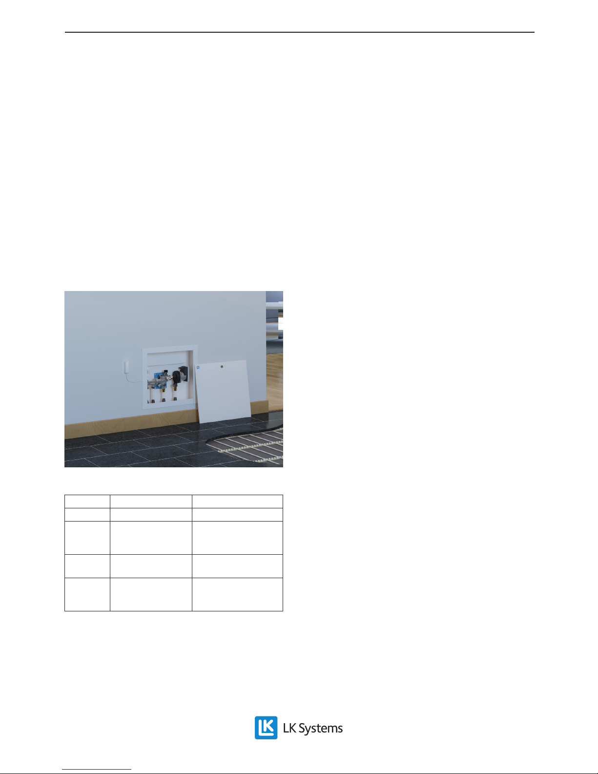
Assembly instructions | LK Minishunt M60
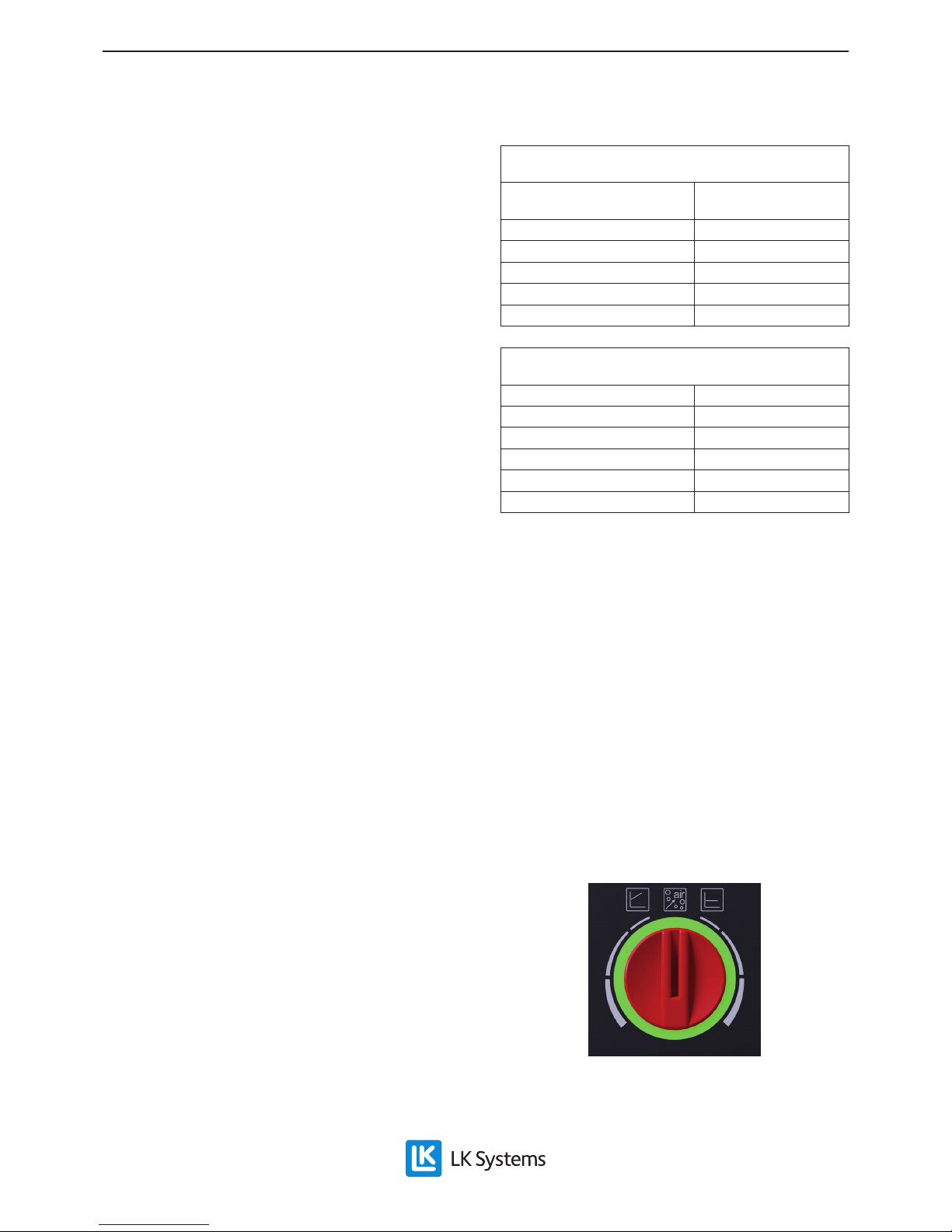
Setting of the temperature limiter for the feed temperature
of the under oor heating.
Dial settings from open
position
Max. temperature
0,0 65 ºC
0,5 57 ºC
1,0 50 ºC
1,5 43 ºC
2,0 35 ºC
Setting of the thermostat with the capillary tube connec-
ted sensor.
Marking on thermostat Room temperature
1 8 ºC
2 14 ºC
3 20 ºC
4 26 ºC
5 32 ºC
Circulation pump
The circulation pump has automatic speed con-
trol, which reduces power consumption and gi-
ves a quieter operation as the pump adjusts the
ow according to the requirements of the system.
A cast arrow on the pump housing indicates the
direction of the ow. For under oor heating it
is recommended that the pump is set to constant
pressure control. Chose the constant pressure
curve that best matches the requirements of the
system, see capacity chart below. Ensure that the
pump never runs dry and the system is well ven-
ted before use. Use the pump´s automatic venting
routine at start up.
Setting the pump function selector
2. Start the pump. Upon start up, use the auto-
matic venting routine to remove accumula-
ted air in the pump. The automatic venting
routine starts after 3 seconds and proceeds
for 10 min. The venting routine is indicated
with a fast ashing green diode light. After
completing the venting process, the con-
stant pressure curve that best matches the
requirements of the system is chosen. See
capacity chart below.
3. Set the switch (2) for single or twin pipe
radiator systems (twin pipe radiator sys-
tem is factory set at delivery). For single
pipe systems the outer hex-screw spindle is
gradually screwed out until correct tempe-
rature is achieved to the radiators. The inner
hex-screw spindle must be screwed out.
For twin pipe systems the outer hex-screw
spindle (dim. 10 mm hex.) must be screwed
in and the inner hex-screw spindle (dim. 4
mm hex.) screwed out.
4. Set the primary temperature from the hea-
ting source to the minishunt to approx. 55
°C.
5. Set the temperature limiter (6) as given in
the table below. Normal setting is approx.
50 °C.
6. Set the thermostat (3) as given in the table
below.
7. Allow the system to stabilize for approx. 10
min.
8. The feed temperature should now be bet-
ween 35-45 °C.
• If the temperature is too low, see heading
Trouble shooting. Note that at start up a
system in an unheated concrete slab, can
take up to 24 hours before the feed tempe-
rature has reached the correct level.
• If the temperature is too high, adjust the
feed temperature using the temperature
limiter (6) as given in the table below.
9. Finish off by resetting the primary tempera-
ture to normal temperature.