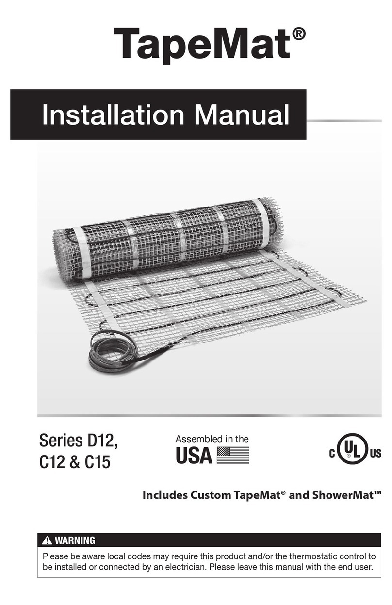
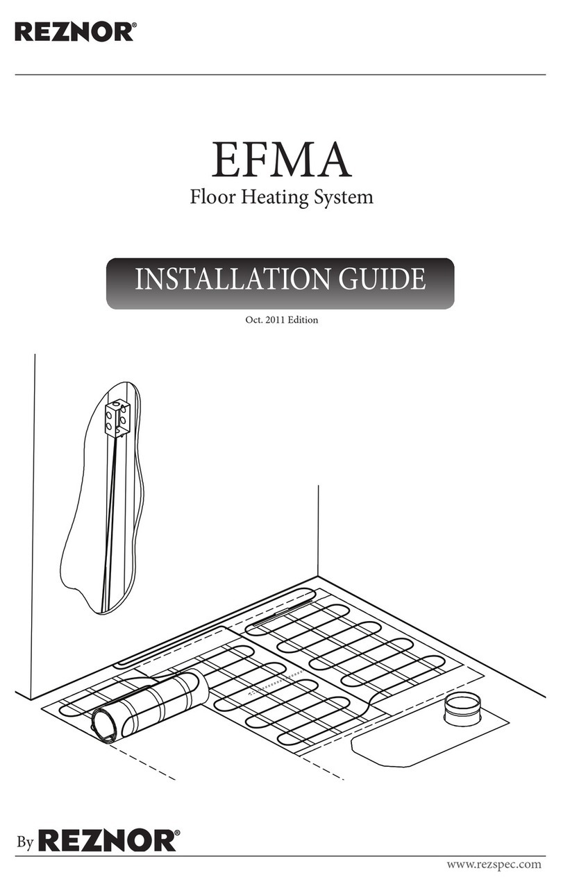
Elements eRibbon User manual

eRibbon
Installation Manual
www.electricunderoorheating.co.uk
Before you begin installing read
through these instructions carefully
and check that you have all the
components required.

2
The eLine Brand
Congratulations on choosing your eRibbon underoor heating product from the eLine
range of under oor heating solutions.
The eLine range has been manufactured to exceed all relevant standards and expectations
considering ease of installation and usability through the lifetime of the product.
The eRibbon Product
The eRibbon mats are constructed from at amorphous metal ribbons covered by two
layers of polyethylene electric insulation. The ribbons are evenly spaced on a mesh
mat providing a simple and easy to install product.
Introduction
Important notes, please read carefully before proceeding with installation
Do’s & Dont’s
Do
Carefully read this instruction manual before starting your installation and follow
the testing procedure as detailed on page 7. Throughout your installation:
• Ensure that the electric circuit that supplies electricity to the eRibbon heating
system is equipped with a 30Ma residual current device (RCD)
• Connect all cold tail leads from the eRibbon heating mats in parallel at the
low level junction box
• Ensure that the total current for all mats does not exceed more than 80% of
the current rating of the MCB/ Fuse
• Use insulation under the mats to reduce costs and warm up time. Check with
your installer to determine the R value of the sub-oor insulation layer
Don’t
• Install mats under walls or partitions, or in areas under heavy cabinets,
closets, or xtures (toilets, sinks, tubs, etc.).
• Install mats within 3cm of any heat conductive building part, such as cold
water pipes.
• Install mats within 5cm of one another, 10cm of any wall, or 15cm of a
replace or hot water pipe.
• Connect any other electrical appliance on the same electric fused spur or RCD
unit of the heating system.
• Install heating mats under wooden oor if the wooden oor is thicker than
18mm.
• Use carpet underlay with thermal resistance greater than 0.8 Tog.
• Install under carpet with thermal resistance greater than 2.0 Tog.
• Overlap heating mats.
• Fold or wrinkle eRibbon heating mats.
• Place heavy/sharp tools (or any other potentially damaging object) on top of
the heating mats.
• Walk unnecessarily on the heating mats.
• Use cellulose insulation.
• Install mats when the room temperature is below -5°C (23°F).
• Install underoor heating mats anywhere except inside buildings.
Tools needed for installation
You will require the following items to install and test the oor warming systems.
• Tape measure, drawing pad and pencil
• Utility knife, scissors
• Cable strippers, screw driver
• Resistance tester (multimeter), insulation resistance tester
You will also need the appropriate tools and materials to install your nished oor surface;
these will probably include products like double-sided tape, eFoam
and various other
tools and materials for your specic project.
Contents of eRibbon system
• Heating mat
• Installation instructions
• Warranty
The following pages contain all the information you will need about the eRibbon.
Please take the time to study this information thoroughly before you attempt to
install this product.
Glossary of Terms
A – Heating element
B – Fibreglass backing mesh
C – Factory made cold tail joint
D – Cold tail power lead
Electrical Requirements
3
Please follow these instructions carefully. If you require assistance prior to
or during your installation please call our helpline on 08714 74 08 18
Electrical Requirements
Before installing the eRibbon you should make allowance for the electrical
connections (see diagram below).
The eRibbon system requires a mains voltage 230/240V and must be connected in
accordance
with the current IEE regulations and building regulations part ‘P’ approved
document.
For areas up to 22m² the eRibbon power connection can be provided through a 13A
switched spur outlet/combined RCD spur outlet. For larger areas a dedicated circuit
should be installed from the local consumer unit.
Conrm your thermostat is suitable to switch the appropriate electrical
load e.g. 15A thermostat 230V is suitable to switch up to 22m² of eRibbon.
If you are required to switch greater electrical load than 15A a suitably sized
thermostat or electrical contactor MUST BE INSTALLED. If in doubt please
call our helpline on 08714 74 08 18.
It is a requirement that all eRibbon systems are protected by a 30ma RCD earth trip
either at the consumer unit or by a combined RCD spur outlet.
When installing in a bathroom or other wet areas the thermostat must be
located outside Zone 2 (0.6m from any wet appliance e.g. shower, sink etc)
or outside of the wet area ideally on the opposite face of the wall.
Important. When designing your electrical installation you should always
consult an electrician concerning your requirements.
eRibbon and Floor Sensor

Installation Instructions
4
Step 1
Draw an installation plan showing the placement of the mats, oor sensor, and
junction box or boxes. Ensure the eRibbon mats are not laid in areas where xed
appliances may be positioned. Decide a suitable position for the thermostat.
Step 2
The oor should now be prepared ready for the eFoam insulation. All loose particles
should be removed and the oor thoroughly cleaned and treated with any proprietary
sealants as normally required.
Step 3
Position and cut the efoam to t your room size securing it with the spray adhesive and
using the utility tape to cover all eFoam joints.
Step 4
Position the double sided tape at regular intervals across the oor where the eRibbon
mats are going to be laid.
Ensure your eRibbon is correctly sized before you unpack the product.
Call 08714 740818 with any questions.

Installation Instructions
5
Step 5
Perform the following tests: Insulation resistance test, a heating cable resistance
test and a oor sensor resistance test. (see page 7) record your ndings in the test &
commission form enclosed in the box.
Step 8
With the eRibbon laid and secure the nished oor surface can now be laid. When
using the Duralay Heatow underlay install directly above the eRibbon
Step 7
Position the oor sensor thermostat probe directly below the electrical connection
point.
The oor sensing probe should be installed in-between two heating ribbons and
secured with the single sided adhesive tape (the oor sensor is used to measure the
maximum temperature beneath the oor).
Step 6
Unfold the eRibbon with the breglass net facing up, lay the eRibbons onto the
eFoam insulation. Using the doublesided adhesive tape clearly xed to the eFoam
ensures the eRibbon is installed with no raised folds. Each pair of cold tails should be
connected to a low level connection point.
Note
After the nished oor covering has been laid perform the following tests:
• Insulation resistance test
• Heating cable resistance test
• Floor sensor resistance test
Record your ndings in the test & commission form enclosed in the box.
Register your warranty online at: www.electricunderoorheating.co.uk/warranty
Note Do not over lap the eRibbon mats

Mat Planning and Layout Instructions
6
Planning your eRibbon
It is important when organising the layout of the mats that you accurately
draw your room area as this will help save time and ensure a smooth
installation.
The eRibbon heating mats should cover at least 65 – 80% of the oor area, the
more coverage the less time needed to heat the area. The eRibbon mats have been
designed with wide heating elements that are positioned closer together so that you
can achieve comfortable temperatures more quickly providing you with a guaranteed
even distribution of heat across your oor.
The eRibbon heating mats are available in several convenient sizes. Choose the
combination of heating mats that best enables you to cover the recommended
65 – 80% of your room. Plan to use the larger heating mats as much as possible and
the smaller mats only as gap llers.
Please nd below a list of the available mat sizes complete with the resistances for
your reference whilst installing the eRibbon.
Product Specications
Q/F Part Code Dimensions Coverage Resistance W/m2
1251 eRib1001 1m x 1m 1m2321-393 150
1251 eRib1015 1m x 1.5m 1.5m2207-241 225
1253 eRib1002 1m x 2m 2m2155-183 300
1254 eRib1025 1m x 2.5m 2.5m2131-153 375
1255 eRib1003 1m x 3m 3m2107-124 450
1256 eRib1035 1m x 3.5m 3.5m2100-115 525
1257 eRib5012 0.5m x 1.2m 0.5m2534-618 90
1258 eRib5015 0.5m x 1.5m 0.75m2445-516 113
1259 eRib5002 0.5m x 2m 1m2321-393 150
1260 eRib5025 0.5m x 2.5m 1.25m2253-309 187
1261 eRib5003 0.5m x 3m 1.5m2199-240 225
1262 eRib5035 0.5m x 3m 1.75m2187-224 262
1263 eRib5004 0.5m x 3.5m 2m2154-183 300
1264 eRib5045 0.5m x 4m 2.25m2146-172 337
1265 eRib5005 0.5m x 4.5m 2.5m2131-153 375
1266 eRib5055 0.5m x 5.5m 2.75m2130-151 412
1267 eRib5006 0.5m x 6m 3m2107-123 450

Testing & Commissioning
Floor Construction Examples
Warranty Validation
To validate your 15 year online warranty registration you must perform the insulation
resistance test, the heating cable resistance test, and the sensor resistance test three times
during the installation process.
1. Before you lay the eRibbon.
2. After you have laid your eRibbon and before you cover your eRibbon.
3. After your nished oor has been laid.
This information must then be recorded on your commissioning record form (enclosed within box).
Insulation Resistance Test
This test is performed to measure the insulation
resistance between conductors and ensures the cable
insulation is not damaged. A low resistance reading
indicates a damaged cable and must be repaired or
replaced.
The insulation resistance tester should be connected
between the main conductor o the cold tails and
earth. The meter should
record a high resistance value
e.g. above 100 Meg ohms.
Floor Construction Examples
The eRibbon allows direct installation of timber laminate, parquet or carpet above the heating mats with no danger of damaging the colour, texture or coating of these delicate
oor coverings.
Carpet
Install the eRibbon and place
your carpet and underlay
directly above mats.
Wood /Laminate
Install the eRibbon and place
your wooden/laminated oor
directly above the mats.
Duralay Heatow
Underlay (optional)
eRibbon
eFoam underlay
Finished oor
screed
Timber oor
Concrete sub-base
Heating Cable Resistance Test
The test is carried out to prove continuity of the heating
element. A low resistance ohm meter should be used
(ie multimeter on ohm setting), connect your meter
onto the mains lead and conrm resistance value
matches that quoted on your specication label on the
eRibbon cold lead joint.
Floor Cable Resistance Test
See Heating Cable Resistance Test and repeat with oor
sensor cable.
7

Troubleshooting
Symptom Probable Causes Corrective action
Floor does not heat No power at controller Check Power supply
MCB Tripped Check the circuit is not overloaded or short circuited
Thermostat not set correctly Refer to thermostat Instructions
eRibbon not correctly connected with thermostat Refer to thermostat Instructions
Floor temperature sensor not connected Refer to thermostat Instructions
Faulty sensor/thermostat Contact the eLine Helpdesk 08714 74 08 18
Heating element cut or damaged Contact the eLine Helpdesk 08714 74 08 18
Floor warming all the time Thermostat not set correctly Refer to thermostat Instructions
Floor temperature sensor not connected Refer to thermostat Instructions
Floor not getting warm enough Thermostat not set correctly Refer to thermostat Instructions
Floor sensor to close to heating element Contact the eLine Helpdesk 08714 74 08 18
Contact the eLine Helpdesk with any questions on 08714 74 08 18
eRibbon
Edison House, Unit 7,
Edison Close, Ransomes Europark,
Ipswich, Suolk, IP3 9GU
United Kingdom
Copyright Elements, a trading division CJ Electrical (Ipswich) Limited. Registered in England no. 2895711
Troubleshooting
Tel: 01473 27 66 80
Fax: 01473 27 66 78
Email: info@electricunderoorheating.co.uk
Web: www.electricunderoorheating.co.uk
8
devilink™`
The asy choice for underoor heating
eCentral
An easy to use touch screen panel which
oers complete control over your entire
heating system wirelessly from one
central control – devilink™.
eStat
Provides total control and exibility
when using your underoor heating
system. With the options of both manual
and fully programmable controls.
eDemist
An ultra thin self-adhesive heating
pad that ts inconspicuously behind
virtually any mirror keeping the mirror
completely mist free.
Call 01473 27 66 80 to receive the latest
underoor heating catalogue
eGuard Monitor
Monitors mats and cables for faults
during installation.
Table of contents
Other Elements Floor Heating System manuals