Penrod Warmset User manual

Installation Manual
Warmset
Floor
heating
system
Warmset Ltd

1
Local building codes and regulations may require all or part of the
installation of this product, and/or the corresponding thermostat to be
performed by a licensed electrician. Leave this manual with the end-user.

2
Warmset mat is an electrical product and should be installed by a qualied
licensed electrician in accordance with local building and electrical codes,
and in accordance with Article 424, Part IX, of the National Electrical Code
(US), ANSI/NFPA 70 and Section 62 of Canadian Electrical Code (CEC) Part 1.
Product Information Specications
Mesh Mat
Attention
Installation 01 Before Beginning
02 Installation Preparations
03 Electrical Rough-in
04 Mat Installation
05 Thermostat Installation
06 Floor Coverings
07 System Start-Up
Troubleshooting
System information System Information table
Mat Data sheet
3
9
25
27
29
Contents

3
Specifications
Warmset Mat
Skill level
requirements
Expected
Performance
The Warmset system is a self-contained heating mat, designed for use em-
bedded in a layer of self-leveling compound and/or thin set. It consists of a
thin heating ribbon tted onto a mesh.
Although the mesh is designed to be cut in order to facilitate installation
around objects and corners, it is important to note :
The heating ribbon cannot be cut.
This includes shorting the lengths to t, or splicing two lengths together.
All Warmset products must be installed by knowledgeable and qualied
persons. An intermediate skill level in electrical wiring is required. Although
Warmset products may be installed by any qualied person (pending local
codes), it is recommended that a certied and licensed electrician roughs in
the power supply wiring.
Please check and adhere to all local codes as they may require all or part of
the installation to be performed by a licensed electrician.
With electric radiant oor heating, performance is never guaranteed. Warm-
set is designed to deliver the performance listed in the above specications
section. The attainable ooring temperature is dependent on the type of
oor, and the overall thermal drain of the oor.
Thorough Insulation is recommended for optimal performance.
Warning Under no circumstance should the heating ribbon be cut, pierced, or
held in place through the use of staples. Only the mesh can be stapled.

4
Specifications
Voltage 120/240 VAC
Power 120 W/m2(11.1 W/ft2)
Max circuit load 15 A
Max circuit overload protection 20 A breaker
Mat length 1 – 40 m (3 – 131 ft)
Mat width 0.5 m (20 in)
ThermostatWarmset Mats must be controlled by a oor-sensing thermostat.

5
Mesh Mat
E
B
C C C
A
D
A.
Fiberglass mesh
B.
Heating ribbon
C.
Double
sided tape
D.
Factory splice
E.
Power lead
F.
Factory end
F

6
A. Tile & Stone /
Vinyl ooring or
Engineered Wood
Floor
B. Latex Portland
Cement /
Flooring Glue
C. Self Leveling
compound
D. Probe
E. Warmset
F. Primer Coating
for Self Leveling
Compound
G. Plywood Floor
A. Tile & Stone
B. Latex- Latex
Modied Thinset
C. Probe
D. Warmset
E. Plywood oor
A. Tile & Stone /
Resilient Flooring
B. Latex Modied
Thinset / Flooring
Glue
C. Self Leveling
compound
D. Probe
E. Warmset
F. Insulated Board
G. Concrete Floor
Tile & Stone / Resilient Flooring with Plywood suboor
Tile & Stone (no self leveling compound) with Plywood suboor
Tile & Stone / Resilient Flooring with Concrete Suboor
G
E
G
F
D
F
E
C
E
D C
B
B
A
D C B
A
A

7
Never install Warmset mat under carpet, wood, vinyl, or other non-masonry
ooring without embedding it in self-leveling mortar, thin-set or thick-set.
Never install Warmset mat in adhesives or glues intended for vinyl tile or
other laminate ooring, or in pre-mix mortars. It must be embedded in
polymer-modied, cement-based mortar.
Never install Warmset mat under built-ins such as cabinets or vanities or
where air does not ow freely. Heating mats installed under built-ins such as
cabinets or vanities, or in small closets, can cause dangerous levels of heat
build-up.
Never connect the Warmset mat to the thermostat before the installation is
completed.
Never use sharp tools or power tools to clean grout lines. Cleaning grout
lines with sharp tools or power tools may damage the heating ribbon and
will void the Warmset Warranty.
Never cut the heating ribbon. If the heating ribbon is cut, it can cause
electric shock, dangerous over-heating, or re. If necessary, the cold leads
may be cut shorter, but never remove them completely from the heating
ribbon.
Never use metal penetrative fasteners such as nails, staples or screws to
secure the heating ribbon to the suboor. Only the mesh can be stapled and
not the heating ribbon.
Never try to create a larger heating mat by splicing one heating mat to
another. Multiple mat cold leads must be connected in parallel.
Never install Warmset mats in walls or ceilings.
Never remove any labeling from Warmset mats. Make sure all appropriate
labels are visible for inspection.
Never install Warmset mats near other heat sources such as light xtures
and chimneys or other ammable devices.
Attention!
>
>
>
>
>
>
>
>
>
>
>
Never

8
Warmset is an electrical product. The appropriate precautions and
care that are associated with electrical installations should be taken.
Always be aware of risks of electric shock, re, and/or injury to
persons. Please read carefully and observe all precautions listed in
these pages.
Attention!
<
<
<
<
<
<
<
<
Caution
Always install a Class “A” GFCI or EGFPD circuit breaker with each Warmset
mat installation. Note: All Warmset thermostats come equipped with a built-
in Class “A” GFCI or EGFPD.
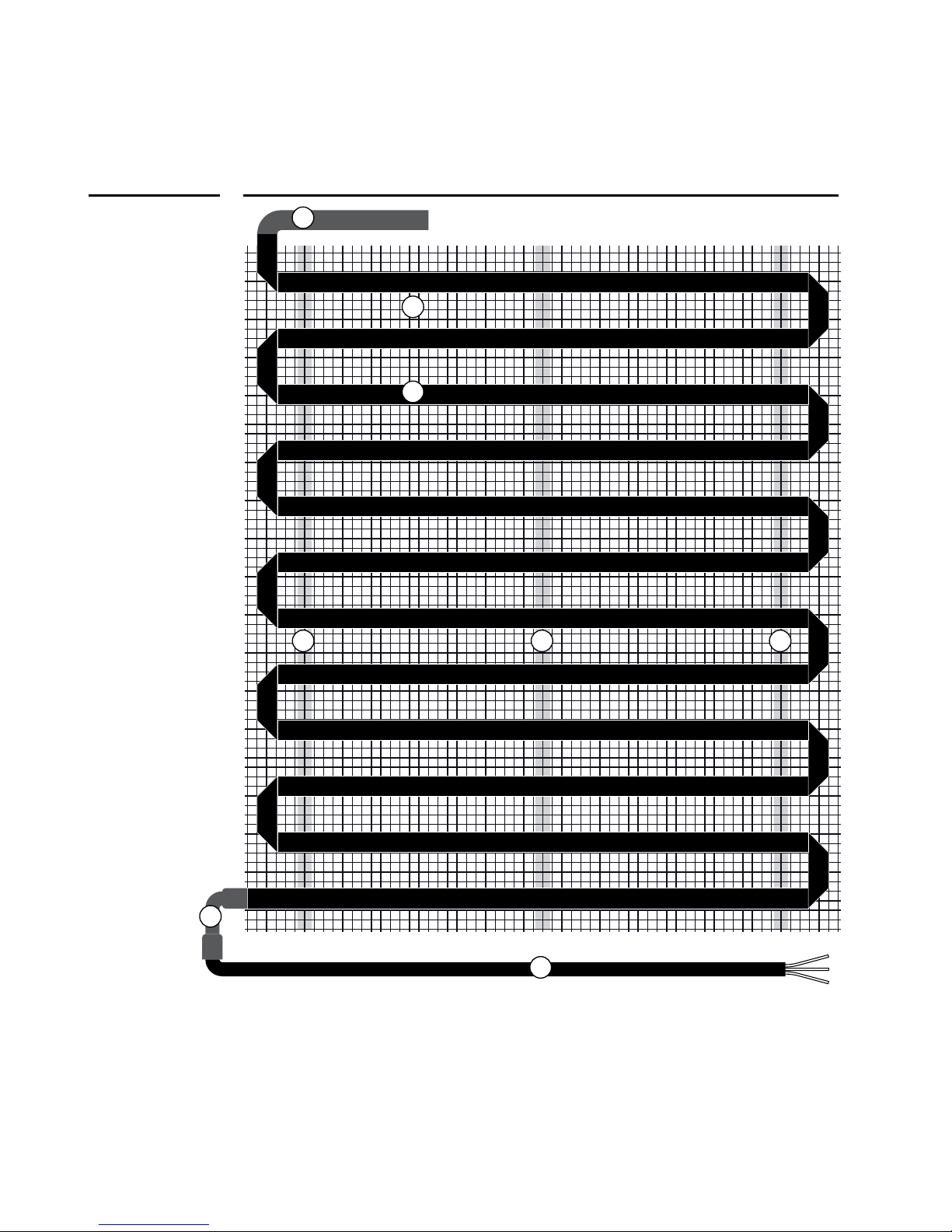
Always use caution when working with tools around Warmset mats. Be
careful not to nick or cut the heating ribbon.
Always completely embed Warmset mats in minimum 3/8”self-leveling
compound and thinset mortar, or other polymer-modied, cement-based
mortar.
Always adhere to all power limitations of the breaker, thermostat, and
chosen Warmset Mat. Be sure the Voltage and Current are appropriate for the
system.
Always install Warmset mats on a dedicated 20 A circuit.
Always make sure all electrical work is done by qualied people in
accordance with local electrical and building codes.
Always use copper wiring to complete the connections in the Warmset
system.
Always seek help or clarity if problems arise. If in doubt about any
installation procedures, or if the product appears to be damaged, please
contact Warmset before starting the installation process.
All Installations must be performed by qualied personnel
in accordance with all local regulations and building codes.
Thoroughly read and follow the installation instructions and
warnings before beginning installation.
Failure to do so can result in electric shock, re, property
damage, personal injury, and/or death.
Always

9
01 Before Beginning
In many applications, Warmset mats can be used as primary heat.
When installing Warmset mat systems, the local environment and
desired results should be considered.
Consider how much heat will be needed to counteract the heat loss
of the space, and try to insulate as effectively as possible.
Make a sketch of the room including all appropriate measurements. These
measurements should be made from wall to wall. Measurements should in-
clude the location and size of major obstacles and installations such as cab-
inets, bathtubs, toilets, etc. Determine the total area to be covered by the
Warmset mat by subtracting the area covered by these built-ins from the total
area of the room.
When planning your installation, consider the following:
Heat will not radiate well beyond roughly 1-1/2” on either side of the
heating ribbon. To avoid cold-spots, consistent coverage is important.
Heating ribbon must not be installed within 2” of a built-in such as a counter
or vanity.
Be sure not to install heating ribbon underneath cabinets or furniture
with no oor clearance. Excessive heat build-up can cause damage.
Do not place the heating ribbon within 4” of other wiring or piping.
When placing heating ribbon, be sure it will not be covered by trim.
The heating ribbon must be completely embedded in self-leveling com-
pound and thinset. Only power leads may exit.
All Warmset Mat mats have a width of 20”.
A gap of 4 to 6”around the edges of the oor should be maintained. This gap is
accounted for by calculating 90% of the total measured square footage. To nd
this value, simply multiply the total square footage found in part 1.1 by 0.9. Use
this result to determine the required Warmset mat sizes for the project.
>
1.1
>
>
>
>
>
>
>
1.2

10
When selecting heating mats remember:
Do not exceed 15 amps through a single thermostat or circuit relay.
Select either 120 VAC or 240 VAC depending on the local availability. Never
mix voltages on the same circuit.
Avoid loading circuit breakers to more than 80% of their capacity. This means
a maximum of 12 amps on a 15 amp breaker.
If the calculated size is not available, don’t use a larger mat, use the next
smallest size. Remember that the heating ribbon must never be cut shorter
to t.
Make sure an appropriate subfloor material has been installed in accordance
with the floor covering, construction requirements, and all local building
codes and regulations. Warmset mat systems can be installed over a variety
of subfloors. Make sure that your chosen subfloor is compatible with cement
adhesives. Common subfloor materials are plywood, existing tiles, cement,
various insulations, and concrete slabs.
When selecting multiple mats, pay close attention to the total current
load. Try to design your system so that it does not exceed 80% of the
rated current of the breaker.
Use a Warmset thermostat (or equivalent) to operate the system. These
thermostats must be purchased separately and are equipped with a
ground fault circuit interrupter (GFCI) that will protect the system in case
of fault. Warmset thermostats have the following specifications:
They are designed for electric inoor heating.
They are able to accept the chosen voltage (120-VAC or 240-VAC).
They have a rated power of 15 A.
They contain a GFCI and include a floor sensor.
They are UL listed for both Canada and the US.
01Before Beginning
<
<
<
<
1.3
1.4
1.5
<
<
<
<
<

11
02 Installation Preparations
Before installing Warmset mats, make sure to thoroughly inspect
the products and carefully plan the site. The ambient air temperature
must be above 0 ˚C or 32 ˚F. Conrm that all plumbing and other
electrical work that will become innaccesible after installation has
been completed.
Materials
Thermostat and oor probe sold separately (see part 1.5)
Appropriate available circuit breakers
A correctly sized electrical box
Junction box with cover (if required)
Electrical Conduit (if required)
Gauge wiring
Check with local building codes for any further safety requirements
Tools
Multimeter with ohmmeter function
A knife or scissors
Wire strippers
Non-conductive builders tape
All necessary small hand tools (drills, screwdrivers, measuring tape,
marker, shears to cut mesh substrate, etc...)
The installer must be familiar with electrical wiring techniques and any
relevant local building codes. A licensed electrician is recommended. If
applicable, the installer should also be familiar with the appropriate oor
covering techniques.
Unpack and inspect all components of the planned Warmset mat system.
Check thoroughly for any visible damage. Verify that everything is the correct
type and size as ordered.
Do not attempt to install a damaged component.
Record all product information about the system in the system information
table found on pages 27–28. Alert the homeowner to this information, and
instruct them to keep it in a safe place.
Do not remove any labels or tags from the product. Your building
inspector will need to be able to see these tags.
>
Items needed
>
>
>
>
>
>
>
>
>
>
>
2.1
2.2

12
200 OH M 200 OH M 200 OH M
The resistance properties of each mat must now be checked. It is essential
that this step is done thoroughly as required throughout the installation.
02Installation Preparations
2.3
Use a high-quality digital ohmmeter or multimeter to make the required mea-
surements. Measure the resistance between the white (or red for 240 VAC)
lead and the black lead. Check that the measurement is within the range listed
on the table at page 29.
Record these values in the system information table. If resistances are
measured slightly below the rated value, it might be due to low air tem-
perature or meter calibration. Contact Warmset if in doubt.
The system should also be checked for short circuits. Measure the white (or
red for 240 VAC) lead to ground (green and yellow), and black lead to ground.
Both of these measurements should read no continuity. Some meters display
this as ‘innite’ ohms or ‘open-line’.
These steps are performed three times in the installation process.
It is very important that they are performed accurately each time.
If there is any inconsistency in the readings, make note of the values and
contact the manufacturer. This could indicate possible damage to the system.
A
D
CB
E
A.
White (or red for
240 VAC)
B.
Black
C.
Ground Lead
(green & yellow)
D.
Black Wire:
to COM
E.
Red Wire:
to OHM
Resistance
<
Insulation
<

13
03 Electrical Rough-in
Warmset heating mats must be connected to a circuit breaker to
protect against circuit overload. Use a 120-VAC single-pole breaker
for 120-VAC systems. Use a 240-VAC double-pole breaker for 240-
VAC systems. A ground fault circuit interrupter is required. If there
is no GFCI built in to the chosen thermostat, one must be installed.
The required rating of the circuit breaker can be determined by the amp draw
of the given heating mats. Simply add the amp requirements from each mat
in the system. If the total amps required for the circuit exceeds 15 amps, a
second breaker must be used. The current draw must never exceed 15 amps
per breaker.
It is recommended to install Warmset mats on new, dedicated breakers; how-
ever it is possible to tap into an existing breaker if there is adequate capacity
available. Remember to leave excess current available for high-draw applianc-
es. Typical hair dryers pull 1200 watts of load, and some can draw more.
Choose a location and install an electrical box for the thermostat. Use an
extra-deep electrical box. For installations with several mats, a larger box may
be required. Electrical boxes should be located in a well ventilated area, and
placed so that the leads from any mats or junction boxes can easily reach it. It
must also be able to connect back to the chosen circuit breaker.
Run a line from the electrical box to the circuit breaker using 14 gauge type
electrical wiring, unless otherwise specied by local building codes. Leave at
least 6 Inches of extra cable in the box.
A junction box must be installed if multiples mats are being used, or if the
mat’s cold leads do not reach the electrical box.
Use a standard junction box and cover. Once the box is in place, run a line
from the junction box to the electrical box using 14 gauge NM type electrical
wiring, or as otherwise specied by local building codes.
3.1
>
>
3.2
3.3
3.4
Note: Be very careful when cutting the mesh. If the heating element
is damaged, do not try to repair it. Please contact the manufacturer.

14
04Mat Installation
4.1
4.2
<
<
<
4.3
Caution
Caution: Do not perform any electrical work unless you are
qualied to do so. Be sure all work is done with the power
turned OFF. Follow all local building and electrical codes.
Warning: risk of electric shock and re. Damage to cold
leads may occur if conductors are routed less than 2” from
the heating ribbon. Refer to installation instructions for
recommended means of routing cold leads.
Before Warmset products can be installed, the oor must be completely swept
of all debris.
Objects on the oor such as nails or other construction material can interfere
with the installation and operation of Warmset mat systems.
Clean the suboor as thoroughly as you can.
All Warmset mats have a width 20”. Depending on the layout and shape of
your room, creative placement of the heating mats may be required.
To facilitate working around obstacles, or unusual room shapes, the heating
element may be removed from the mesh. When the heating ribbon is
removed from the mesh to facilitate working around obstacles or unusually
shaped rooms, the measured center-to-center spacing between runs must be
maintained throughout the installation. However, in order to maintain even
heat dissipation, avoid removing excessive amounts of mesh.
Depending on your installation, large gaps between the mesh can exist. If you
are laying large quantities of heating mats outside of the mesh, pay close at-
tention to your spacing. Remember that gaps larger than 1.5” can create
cold spots.
Verify that the wiring will reach the required electrical box or junction box.
Never run wiring back over mats to reach these boxes.
Warmset heating mats can be cut for any straight or right angle.
This process is shown on the next page
Whencuttingandplacingmats,rememberto try and spacethem appropriately.
There isn’t minimum bending radius but it is important to ensure there is
no overlap between installed mats. Overlapped mats can cause dangerous
overheating.

15
04 Mat Installation
A.
Cut the mesh
on the dotted
line
B.
Be careful to
not damage the
heating element
A
B

16
04Mat Installation
C.
Once the mesh
has been cut,
the element can
be unfolded
to the desired
angle.
D.
The mats can
be cut for
several angles,
allowing the
system to work
around almost
any obstacles.
C
C
D

17
04 Mat Installation
Unroll the Warmset mat to cover the space. It is important to check the layout
by test-tting the entire system. Conrm that there are no folds or large
ripples. (UL 1683, 65.3c – That the heating product shall not extend beyond
the room or area in which it originates.)
Once the system has been tted in place; it must be secured to the sub-oor .
Warmset mats should be secured to the oor using non-conductive, double-
sided building tape. If need be, stabilize your installation with staples or hot
glue. At no time should you ever staple the heating ribbon itself. This will
jeopardize the functionality of your system. Only the mesh should be stapled
or glued.
As the mats are being laid, it is important to ensure that they lie as at as
possible. This will help make a smooth surface for spreading mortar.
Do not completely cover the heating ribbon with tape.
Once the entire system has been tted and secured, test the resistance of the
system as outlined in part 2.3, and note it in the table located on page 28.
Connect the leads from the heating mats back to the electrical box or
junction box. The cold leads can be installed with or without electrical
conduit (recommended for added protection) depending on code re-
quirements. If conduit is required by code, install 1/2” (minimum) conduit
from the bottom plate up to the electrical box. For multiple power leads
(multiple mats) install 3/4” conduit.
Drill a 1/2” hole in the base plate directly below the electrical box, or if it
being used, junction box. Run the line from the mats through this hole up
to the junction box or electrical box.
4.4
4.5
>
>
4.6
4.7
>
Never cut the heating ribbon to make it t.
Doing so will cause the system to malfunction dangerously.
Caution

18
UL 1683, 65.3h – Mark the appropriate circuit breaker referencing which
branch circuit supplies the Warmset heating system. When using multiple
mats, the mats should be connected in parallel. If multiple mats are being
installed, label the leads as they enter the junction box. Connect these mats to
the line going from the junction box to the electrical box.
The thermostat oor sensor can be installed with or without electrical conduit
(recommended for added protection) depending on code requirements. Do
not place the sensor in the same conduit as the cold leads to avoid possible
interference.
Open a separate knockout in the bottom of the thermostat box, and feed the
sensor (and conduit, if used) through the knock-out. Feed it down through
the cut-out in the bottom plate, and out into the oor where the heating mat
will be installed.
4.8
<
<
04Mat Installation
A.
The thermostat
oor sensor
can be installed
exactly between
two heating
elements and
more than 10 cm
from the plies
B.
Parallel
connection
AB

19
Stop and read all manuals included with thermostat.
Connect your thermostat to the electrical box installed in part 3.2.
Connect the lines coming from the mats or junction box to the load ter-
minals on the thermostat, and the line coming from the circuit breaker to
the power terminals.
Connect the ground cables from the mats or junction box directly to the
ground line from the circuit breaker. (Green & yellow cable)
Connect the sensors for your thermostat. The oor sensor should be placed
roughly one foot from the wall. When placing the oor sensor, it is important
to make sure it’s located exactly between two heating ele-ments and more
than 5”from the folds (g A - page 18). The sensor cable must pass outside the
electrical box and follow the wall down to the oor.
Position the sensor cable such that it does not come in contact with
the oor heating wires. The sensor must be centered between two oor
heating ribbons for best temperature control.
Do not staple the sensor head (the plastic end) to the oor. Doing so might
damage the sensor. Any damage might not be noticeable during testing but
can become apparent several days later.
At this point, it is recommended to take clear and thorough photos
of the entire system.These can be very valuable for later remodeling
work. Attach these photos to this manual, and leave them with the
homeowner after installation.
05 Thermostat Installation
Note
5.1
>
>
5.2
>
>
5.3
Make sure there is no power applied to the system before
it’s fully ready for nal testing.
All installation work must be done with the power turned off.
Caution
Table of contents