manuals.online logo
Brands
  1. Home
  2. •
  3. Brands
  4. •
  5. Hanna Instruments
  6. •
  7. Controllers
  8. •
  9. Hanna Instruments HI520 User manual

Hanna Instruments HI520 User manual

Hanna Instruments Inc., 584 Park East Drive, Woonsocket, RI 02895 USA www.hannainst.com
HI520 Dual-Channel Universal Process Controller
Quick Reference Guide
HI510-02 wall mount
HI510-01 panel mount
Hanna is committed to developing and deploying digital solutions
with a positive impact on the environment and climate.
Scan the QR code or follow the link to download the user
manual. https://manuals.hannainst.com/HI520
HI520-0320
3relays & 2analog outputs
HI520-0540
5relays & 4analog outputs
Package contents
• HI520 controller
• Cable gland seals (1 set)
• Power cable, 3 m (9.84’) long
• Instrument quality certificate and quick reference guide
Note: Save all packing material. Any damaged or defective item must
be returned in its original packing material with the supplied accessories.
Controller models
Dear Customer, thank you for choosing Hanna Instruments.
HI520 is a universal process controller intended for applications where
simultaneous measurement and control of process variables is needed.
Main features
• Hanna Smart digital probes
• RS-485 / Modbus serial communication protocol
• Independent / sequential channel control
• Flexible function assignment for control, cleaning, Hold relays
• IP65 / NEMA 4X protection
• Wall, pipe, panel mounting kit (sold separately)
Safety precautions
• Electrical connection must be carried out by specialized personnel
only. Read safety manual instructions before connecting to power.
• Do not make electrical connections with device connected to power.
• Do not run other cables through the designated power cable gland.
• Have a disconnect switch installed in the vicinity of the instrument
to ensure electrical circuit is de-energized for installation.
Opening the enclosure
• Loosen the four screws, enough for the springs to push them out.
• Grasp the front bezel and swing open to access the two-
terminal power supply board.
Connecting to power
• Remove the blank plug and thread the cable through the power
cable gland.
• Remove the safety cover to access high voltage Terminal 1.
• Connect the probe leads to the terminal connector POWER.
Follow lead markings for correct wiring on the supply
board. Each leads location is marked.
• Ensure the power connector is seated correctly in the power socket.
• Replace safety cover over Terminal 1.
Power cable
SIGNAL
PATH
POWER
PATH
Blank plug
Probe accessories (sold separately)
Saddle
BL120-5XX
Flow cell
BL120-4XX
Immersion electrode holders
HI60501 HI60503
HI510-03 pipe mount
Hanna Instruments Inc., 584 Park East Drive, Woonsocket, RI 02895 USA www.hannainst.com
HI520 Dual-Channel Universal Process Controller
Quick Reference Guide
Please retain for future use.
QR520 12/22
Controller wiring
• Terminal 1 (high voltage): POWER, ALARM, REL 1 to REL 5
(relays)
• Terminal 2 (low voltage): COMM (RS-485), PROBE1 and
PROBE2, IN1 and IN2 (digital inputs), A01 to A04 (analog
outputs)
• Follow lead markings to ensure output leads are wired
to the correct position on the main board.
COMM
-BA+
IN1 IN2 A01 A02 A03 A04
PROBE
-BA+
Terminal 1
Terminal 2
PROBE 1
-BA+
PROBE 2
-BA+
INP
-I +
A+
B
—A+
B
—
Probe wiring
1. With controller disconnected from power run the probe cable
through the correct conduit opening.
2. Connect probe leads to the terminal connector PROBE1 or PROBE2.
Follow lead markings for correct wiring of output leads.
3. Carefully put the wired terminal connector into place on the board.
4. Position excess cable through cable gland before tightening the nut.
5. Remove the ground screw and hardware located below the probe
connector. Attach the ground lead ( g).
Probe cabling color code
Marking Attached Cable Patch Cable Functionality
–GREEN BLACK 0 V
BWHITE WHITE RS-485 D –
AYELLOW BLUE RS-485 D+
+BROWN RED 5 V
gGREEN-YELLOW GREEN-YELLOW PROTECTIVE GROUND
Terminal 1Terminal 2
Supported probe series and configurations
HI10 X X –Y8Z Z pH & Temperature
XX 06 PTFE junction
16 Ceramic junction
Y
Glass sensor
Titanium Matching Pin
pH range Temperature range
1Low
temperature 0.00 to 12.00 pH –5.0 to 80.0 °C
(23.0 to 176.0 °F)
3High
temperature 0.00 to 14.00 pH 0.0 to 100.0 °C
(32.0 to 212.0 °F)
4Fluoride
resistant 0.00 to 10.00 pH –5.0 to 60.0 °C
(23.0 to 140.0 °F)
HI20 X X – Y 8Z Z ORP & Temperature
XX 04 PTFE junction
14 Ceramic junction
Y
Sensor type mV range Temperature range
1Platinum ± 2000 mV –5.0 to 100.0 °C
(23.0 to 212.0 °F)
2Gold
HI7630 –Y8Z Z EC & Temperature
Y
2
Two-electrode
cell conductivity,
SS AISI 316,
cell constant
k ≈ 0.1/cm
EC 0.000 µS/cm to 30.00 mS/cm
TDS 0.000 mg/L to 15.00 g/L (TDS factor 0.5)
RES 34 Ω•cm to 99.99 MΩ•cm
Temperature 0.0 to 50.0 °C (32.0 to 122.0 °F)
4
Four-ring
conductivity,
platinum on glass,
cell constant
k ≈ 1.0/cm
EC 0.0 µS/cm to 999.9 mS/cm
TDS 0.0 mg/L to 400.0 g/L (TDS factor 0.5)
RES 1.00 Ω•cm to 9.99 MΩ•cm
Seawater Salinity 400.0 %NaCl, 42 psu, 80 ppt
Temperature 0.0 to 100.0 °C (32.0 to 212.0 °F)
HI7640 –1 8 Z Z Galvanic DO & Temperature
Galvanic sensor
Concentration 0.00 to 50.00 mg/L (ppm)
Saturation 0.0 to 500.0 %
Temperature −5.0 to 50.0 °C (23.0 to 122.0 °F)
HI7640 –5 8 Z Z Optical DO & Temperature
Optical sensor
Concentration 0.00 to 50.00 mg/L (ppm)
Saturation 0.0 to 500.0 %
Temperature −5.0 to 50.0 °C (23.0 to 122.0 °F)
8Smart probe, with RS-485 connection
ZZ 00 supplied with DIN connector (without cable)
05, 10, 15, 25, 50 fixed cable length (in meters)
pH ORP EC Galvanic DO Optical DO
Probes are sold separately.
Scan the QR code to download
the user manual:
Other manuals for HI520

2

Other Hanna Instruments Controllers manuals

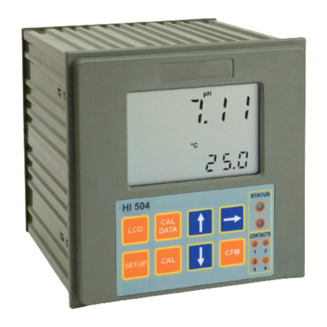
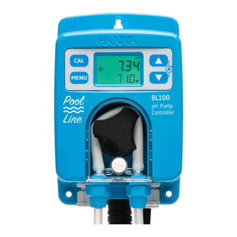
Hanna Instruments HI 504 User manual

Hanna Instruments

Hanna Instruments HI 504 User manual

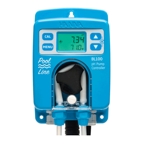
Hanna Instruments BL121 User manual

Hanna Instruments

Hanna Instruments BL121 User manual

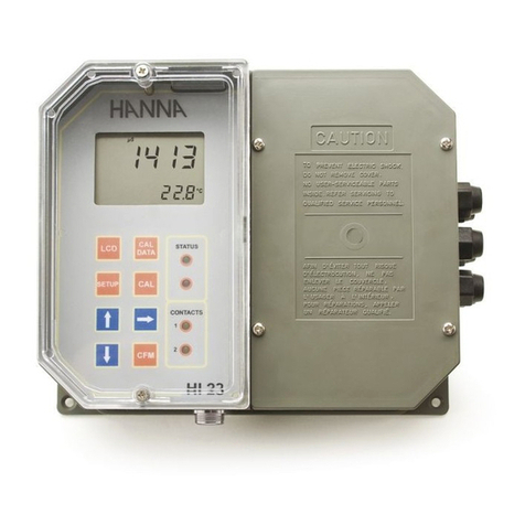
Hanna Instruments HI 24 Series User manual

Hanna Instruments

Hanna Instruments HI 24 Series User manual

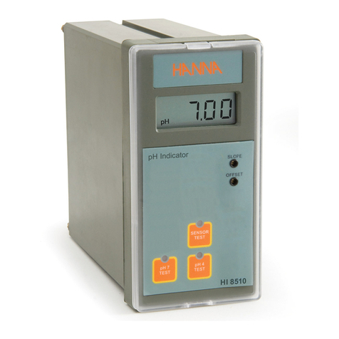
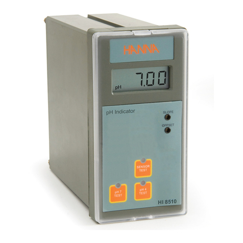
Hanna Instruments HI 8510 User manual

Hanna Instruments

Hanna Instruments HI 8510 User manual

Hanna Instruments HI 7871 User manual

Hanna Instruments

Hanna Instruments HI 7871 User manual

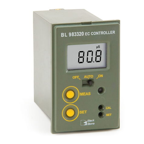
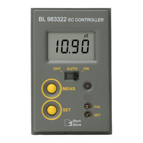
Hanna Instruments BL 983322-0 User manual

Hanna Instruments

Hanna Instruments BL 983322-0 User manual

Hanna Instruments BL 983324-0 User manual

Hanna Instruments

Hanna Instruments BL 983324-0 User manual

Hanna Instruments HI520 User manual

Hanna Instruments

Hanna Instruments HI520 User manual

Hanna Instruments mV 602 Series User manual

Hanna Instruments

Hanna Instruments mV 602 Series User manual

Hanna Instruments HI 9931 User manual

Hanna Instruments

Hanna Instruments HI 9931 User manual

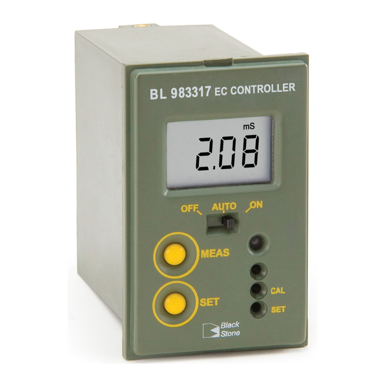
Hanna Instruments BL 983317-0 User manual

Hanna Instruments

Hanna Instruments BL 983317-0 User manual

Hanna Instruments HI 22 Series User manual

Hanna Instruments

Hanna Instruments HI 22 Series User manual

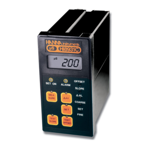
Hanna Instruments HI 8931 User manual

Hanna Instruments

Hanna Instruments HI 8931 User manual

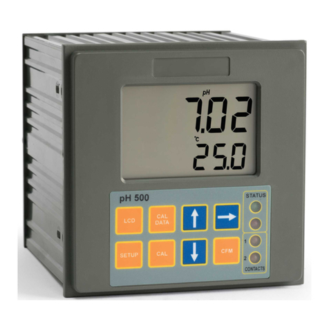
Hanna Instruments pH 500 Series User manual

Hanna Instruments

Hanna Instruments pH 500 Series User manual

Hanna Instruments BL120 User manual

Hanna Instruments

Hanna Instruments BL120 User manual

Hanna Instruments BL 983318-0 User manual

Hanna Instruments

Hanna Instruments BL 983318-0 User manual

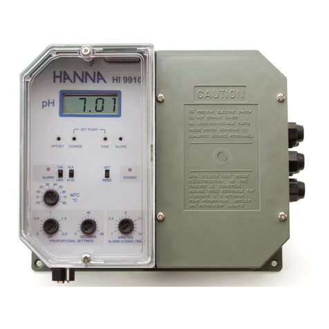
Hanna Instruments HI 9912 User manual

Hanna Instruments

Hanna Instruments HI 9912 User manual

Hanna Instruments HI 21 Series User manual

Hanna Instruments

Hanna Instruments HI 21 Series User manual

Hanna Instruments HI 504 User manual

Hanna Instruments

Hanna Instruments HI 504 User manual

Hanna Instruments BL 983319-0 User manual

Hanna Instruments

Hanna Instruments BL 983319-0 User manual

Hanna Instruments HI 8510 User manual

Hanna Instruments

Hanna Instruments HI 8510 User manual

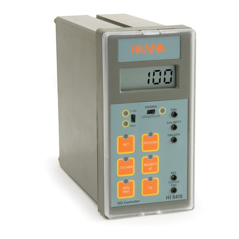
Hanna Instruments HI 8410 User manual

Hanna Instruments

Hanna Instruments HI 8410 User manual

Hanna Instruments HI 700 Series User manual

Hanna Instruments

Hanna Instruments HI 700 Series User manual

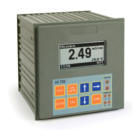
Hanna Instruments HI 720 User manual

Hanna Instruments

Hanna Instruments HI 720 User manual

Popular Controllers manuals by other brands

Berker 7534 10 12 manual

Berker

Berker 7534 10 12 manual

Newport SMC100CC Command Interface Manual

Newport

Newport SMC100CC Command Interface Manual

Haiku L Wired Wall Control installation manual

Haiku

Haiku L Wired Wall Control installation manual

Welker HR Installation, operation and maintenance manual

Welker

Welker HR Installation, operation and maintenance manual

Mitsubishi LE-40MTA-E instruction manual

Mitsubishi

Mitsubishi LE-40MTA-E instruction manual

Atkinson Electronics SUNEXPLORER III Series manual

Atkinson Electronics

Atkinson Electronics SUNEXPLORER III Series manual

Rodix FEEDER CUBE FC-40 Plus Series manual

Rodix

Rodix FEEDER CUBE FC-40 Plus Series manual

YASKAWA YRC1000 Startup guide

YASKAWA

YASKAWA YRC1000 Startup guide

Carlisle Ransburg 9060 Service manual

Carlisle

Carlisle Ransburg 9060 Service manual

Fright Ideas BooBox FlexMax quick start guide

Fright Ideas

Fright Ideas BooBox FlexMax quick start guide

Smartgen ACC4100 user manual

Smartgen

Smartgen ACC4100 user manual

Danfoss VLT Micro Drive quick guide

Danfoss

Danfoss VLT Micro Drive quick guide

ontrac Easytrac operation instruction

ontrac

ontrac Easytrac operation instruction

HYDRO-RAIN HRC 390 SERIES Quick start instructions

HYDRO-RAIN

HYDRO-RAIN HRC 390 SERIES Quick start instructions

Horizont turbomax AN800 instruction manual

Horizont

Horizont turbomax AN800 instruction manual

Targetti Chroma-Cue installation guide

Targetti

Targetti Chroma-Cue installation guide

ESBE CRC110 series Technical description

ESBE

ESBE CRC110 series Technical description

Contro l4 HC-800 installation guide

Contro l4

Contro l4 HC-800 installation guide

manuals.online logo
manuals.online logoBrands
  • About & Mission
  • Contact us
  • Privacy Policy
  • Terms and Conditions

Copyright 2025 Manuals.Online. All Rights Reserved.