manuals.online logo
Brands
  1. Home
  2. •
  3. Brands
  4. •
  5. Hanover
  6. •
  7. Patio Furniture
  8. •
  9. Hanover Monaco MONACO7PCSW User manual

Hanover Monaco MONACO7PCSW User manual

HanoverOutdoorFurniture
IMPORTANT
Ifyouhaveanyproblemswiththisproduct(missingordamagedparts,assemblyissues,etc.),
PLEASEDONOTRETURNTOTHERETAILER/STORE
fromwhereyoupurchasedtheproduct.
PleasecallourToll‐FreeCustomerServiceHotlineat:1‐877-397-5144
Between9:00AMand5:00PMEasternTime,MondaythroughFriday
Orvisitourwebsiteat:www.hanover‐products.com
Toexpediteanyfuturewarrantyclaims,pleaseretaintheInstructionSheet,Warranty
Cardandreceiptforfutureuse.
For additionalon‐linesupportonassembly,troubleshootingandcare&maintenanceofyouroutdoor
furniture,pleasevisitourwebsiteat:www.hanover‐products.com.
6/1/2015(a)
E
F
H
PARTS LIST DESCRIPTION ORDER PART #
NUT COVER
BOLT COVER
HEX BOLT DRIVER
HEX WRENCH
1/4" NUT
1/4" X 25 MM BOLT
TABLE LEG
LEG CONNECTOR
BRACKET
TABLE TOP
QTY
8
4
1
1
12
8
4
4
1
1
HW0027
HW0105
HW0006
HW0009
HW0004
HW0014
HW0037
FC0030
FOOT CAP
FACTORY ASSEMBLY
FOOT CAP
A
B
C
D
E
F
G
H
I
J
KG0003 1
TOUCH-UP PAINT
IMPORTANT!! PLEASE READ ENTIRE INSTRUCTION SHEET BEFORE ASSEMBLY!!
TO EXPEDITE ANY FUTURE WARRANTY CLAIMS, PLEASE KEEP INSTRUCTION SHEET, WARRANTY CARD AND RECEIPT
Step3: Attach a leg to the leg connector bracket by carefully
guiding the bolts already in place on the table legs
(each leg has two bolts) through the holes in the leg
connector bracket. Add a washer and a nut to the end
of each bolt . Hand tighten only. Do
not tighten completely. Repeat on the other three legs.
as shown in Fig.2
Step 4: After making any necessary adjustments to the
alignment of the table legs and the leg connector
bracket, use the hex bolt driver and hex wrench to
tighten all nuts and bolts. Note: each bolt and nut
must be tightened a few revolutions at a time. In
order to apply equal pressure to all bolt joints, we
recommend working in a cross corner (X fashion).
Repeat until all bolts are tight. Do not over tighten.
Over tightening may strip bolts. Cover all nuts and
bolts with covers.
Step 5: With the help of another person, turn the table in the
upright position. Your table is now ready for use. If
you have any questions, please call our Customer
Service Center at 1-800-416-3511.
IMPORTANT NOTE: Damage to welds or frames
resulting from over tightened bolts or improper assembly
is not covered under our warranty. Please read all
instructions carefully before assembly. If you have any
questions regarding your assembly, call our Customer
Service Center at 1-800-416-3511.
* NOTE: PARTS SHOWN ON PARTS LIST ARE NOT TO SCALE
Step 1: Remove all protective materials and set parts on a flat,
non-abrasive surface. Identify parts packed in carton
against the parts list. If you are missing any parts or are
unsure how to proceed with assembly, call our Customer
Service Center at 1-800-416-3511. Do not attempt
assembly if any parts are missing or damaged.
Step 2: Place the table top upside down on a flat, non-abrasive
surface. Attach a table leg to the table top by using the
bolt and washer as shown in Fig.1. Place the leg beneath
the table top corner bracket. Guide the bolt through the
hole in the table top corner bracket and into the pre-drilled
hole in the table leg. Hand tighten only 3-4 revolutions
only. Do not tighten completely. Repeat for the other
three legs. Ø6.5 X 1.0 MM
WASHER
D
F
G
B
C
A
UMBRELLA POLE
LOCK KNOB & NUT
FACTORY ASSEMBLY
G0091
& HW0448
Fig.1
Fig.2
G0157
UMBRELLA HOLE
PROTECTIVE RING
FACTORY ASSEMBLY
ALF41817
ADS17500
IMPORTANT!! PLEASE READ ENTIRE INSTRUCTION SHEET BEFORE ASSEMBLY!!
TO EXPEDITE ANY FUTURE WARRANTY CLAIMS, PLEASE KEEP INSTRUCTION SHEET, WARRANTY CARD AND RECEIPT
FRONT SEAT
SUPPORT BAR
Fig.1
B
C
F
Fig.3
D
E
FOOT CAPFOOT CAP
PARTS LIST PARTS LISTDESCRIPTION DESCRIPTIONORDER PART # ORDER PART #
SEAT FRAME BOLT COVER HW0022
FC0030
FOOT CAP
FACTORY ASSEMBLY
SEAT BASE
1/4" X 35 MM
BOLT
1/4" X 45 MM
BOLT
Ø6.5 X 1.0 MM
WASHER
HW0142
HW0040
HW0004
QTY QTY
1
A
B
C
D
E
F
G1
2
2
2
2
1HW0252
Fig.2
IMPORTANT NOTE: Your sling seat may appear to be slightly warped. This is not unusual.
Proper assembly procedure will straighten out the sling seat in the frame. There are four bolts
used to attach the seat frame to the seat base. After inserting all the bolts, each of these bolts
must be tightened a few revolutions at a time in rotation.
Step 1: Identify all parts packed in the carton against the parts list. Remove all protective
materials. Set parts on a flat, non-abrasive surface to avoid scratching. If you are missing
any parts or are unsure how to proceed with assembly, call our Customer Service Center
immediately at 1-800-416-3511. Do not attempt to assemble chair if any parts are
missing or damaged.
IMPORTANT NOTE: Assembling this chair requires attaching the sling seat frame to the seat
base. We recommend two people work together to assemble the chair since it is critical that all
the holes in the seat frame are aligned exactly with the holes in the seat base. All bolts need to
be inserted and tightened into the fixed nuts in a straight and direct path. Inserting the bolts at
even the slightest angle could strip the nuts and bolts, damaging the entire chair.
Step 2: Working from behind the chair, have another person stand in front of the chair and position
the sling seat frame in between the arms of the seat base as shown in Fig.1 so that the holes
on both sides of the upper portion of the seat frame back align with the fixed nut holes in
the seat base.
Step 3: Working from the front of the chair, add a washer to a 1/4"x45 mm bolt. From the
underside of the front seat support bar, insert the bolt with washer through one of the holes
in the seat support bar, into the fixed nut inside the lower front portion of the seat base as
shown in Fig.2. Hand tighten 3-4 revolutions only. Do not tighten Completely. Repeat
for opposite side of chair.
Step 4: From behind the chair, insert a 1/4"x35 mm bolt through the back arm portion of the seat
base and into the fixed nut in the seat frame as shown in Fig.3. Make sure the bolt is
inserted exactly straight! Hand tighten 3-4 revolution only. Do not tighten completely.
Repeat for opposite side of chair.
Step 5: Tighten all bolts with the hex bolt driver. Each bolt must be tightened a 3-4 revolutions
only at a time. Begin with top left bolt. Move to bottom right bolt then to top right bolt,
followed by bottom left bolt. Repeat this "X" pattern until all bolts are tight. Do not over
tighten bolts. Over tightening may strip bolts or nuts, damaging the entire chair. Cover
1/4"x35 mm bolts with bolt covers.
Step 6: Examine the chair from the front. If the sling seat does not appear tight or straight in the
seat base, repeat steps 3, 4 and 5. If you do not feel your chair is assembled properly, or
you have any questions, call our Customer Service Center at 1-800-416-3511.
IMPORTANT NOTE: Damage to welds or frames resulting from over tightened bolts or
improper assembly is not covered under our warranty. Please read all instructions carefully
before assembly. If you have any questions regarding your assembly, call our Customer
Service Center at 1-800-416-3511.
* NOTE: PARTS SHOWN ON PARTS LIST ARE NOT TO SCALE
HEX BOLT DRIVER
A
SLING TUBE CAP
FACTORY ASSEMBLY FC0358
AN0523
AN0524
ADS17501
IMPORTANT!! PLEASE READ ENTIRE INSTRUCTION SHEET BEFORE ASSEMBLY!!
TO EXPEDITE ANY FUTURE WARRANTY CLAIMS, PLEASE KEEP INSTRUCTION SHEET, WARRANTY CARD AND RECEIPT
Step 1: Identify all parts packed in carton against the parts list. Remove all protective materials.
Place parts on a non-abrasive surface to avoid scratching. If you are missing any parts or are
unsure as how to proceed with the assembly, call our Customer Service Center at
1-800-416-3511. Do not attempt assembly if any parts are missing or damaged.
Step 2: Place the swivel base (with rocker assembly) on a flat, solid surface. Make sure the rocker
assembly is positioned all the way into the base. It may have shifted or vibrated out during
shipment.
Step 3: Important: We recommend 2 people work together to assemble the chair. Note the
arrow labels on the "U" bar and the rocker assembly. Also note the horseshoe shape of the
rocker plate. Point the open end of the horseshoe away from you. The arrows on the rocker
assembly should be pointing towards you. Set the chair frame on the rocker assembly with
front of the seat facing you and the arrows on the "U" bar pointing towards you as shown
in Figure 1. This is very important for a safe, balanced rocking motion. If chair frame has
been properly positioned on the rocker assembly, all arrows on the "U" bar and rocker
assembly will be pointing in the same direction.
Step 4: Critical Step: The "U" metal plates must be installed in the proper location. Read this
step and carefully examine. Insert the "U" metal plate, so that the "U" bar and rocker plate
are between both sides of the "U" metal plate. Make sure that the holes in the "U" metal
plate are completely aligned with the holes in the "U" bar as shown in Figure 1. Guide the
bolts through the holes on the top side of the "U" metal plate, through the holes in the
"U" bar portion of the chair, through the holes in the rocker plate and then, most importantly,
through the holes in the bottom side of the "U" metal plate. It is very important that the
holes in the bottom portion of the "U" metal plate be placed directly beneath the holes in the
rocker plate. Add a spring washer and a nut to each bolt as shown in Figure 2. Hand
tighten nuts 3-4 revolutions only. Repeat the same procedure on the other side.
CAUTION: Failure to place "U" metal plates under the rocker plates and above the
"U" bar exactly as shown in diagram will cause the bolt heads and nuts to damage the
structure of the rocker plates and the "U" bar. Damage due to over tightening of bolts
or improper assembly could cause injury and may void your warranty.
Step 5: Tighten all nuts and bolts with the hex wrenches provided. Do not over tighten. Remove
arrow labels from "U" bar and rocker assembly. Cover bolts with bolt covers.
Step 6: Your chair should be ready for use. If your chair is not rocking properly, double-check your
assembly procedure, especially Step 3. If the chair rocks too far forward to or is difficult to
rock backwards, you have probably installed the seat frame backwards on the rocker
assembly. If you need further assistance, please call our Customer Service Center
at 1-800-416-3511.
IMPORTANT NOTE: Damage to welds or frames resulting from over tightened bolts or
improper assembly is not covered under our warranty. Please read all instructions carefully
before assembly. If you have any questions regarding your assembly, call our Customer
Service Center at 1-800-416-3511.
NOTE: MAKE SURE ARROWS
FROM BOTH THE "U" BAR
AND ROCKER ASSEMBLY
ARE POINTING IN THE
SAME DIRECTION!
SEAT DESIGNS MAY
VARY BUT THE ASSEMBLY
IS THE SAME
HEX WRENCH-1 HW0008 1
HEX WRENCH-2 HW0007 1
QTY
PARTS LIST DESCRIPTION ORDER PART #
* NOTE: PARTS SHOWN ON PARTS LIST ARE NOT TO SCALE
BOLT COVER HW0028 8
QTY
SWIVEL BASE &
ROCKER
ASSEMBLY
5/16" X 40 MM
BOLT
HW0003
"U" METAL
PLATE
CHAIR FRAME
PARTS LIST DESCRIPTION ORDER PART #
2
4
4
1
1
HW0295
HW0618
A
B
C
D
E
F
G
Ø8.0 X 2.3 MM
SPRING WASHER
FOOT CAP
A
B
Figure 1
Figure 2
ROCKER PLATE
E
C
D
G
"U" BAR
ROCKER
ASSEMBLY
"U" BAR
5/16" NUT HW0015 4
F
FC0359
FOOT CAP
FACTORY ASSEMBLY
HW0619
ROCKER PLATE
FACTORY ASSEMBLY
SLING TUBE CAP
FACTORY ASSEMBLY FC0358
AR19238
AR19239

This manual suits for next models

3

Other Hanover Patio Furniture manuals

Hanover Manchester MNCR3PC-GRY User manual

Hanover

Hanover Manchester MNCR3PC-GRY User manual

Hanover HANLGTRUNK Datasheet

Hanover

Hanover HANLGTRUNK Datasheet

Hanover BRIGDN5PCSQ User manual

Hanover

Hanover BRIGDN5PCSQ User manual

Hanover Brigantine Dining Table User manual

Hanover

Hanover Brigantine Dining Table User manual

Hanover BGC08006 User manual

Hanover

Hanover BGC08006 User manual

Hanover ORL4PCCFPSW2-BRY User manual

Hanover

Hanover ORL4PCCFPSW2-BRY User manual

Hanover Riley RLYDN7PC-GRY User manual

Hanover

Hanover Riley RLYDN7PC-GRY User manual

Hanover 11200-UMB11FT-BLUSL User manual

Hanover

Hanover 11200-UMB11FT-BLUSL User manual

Hanover TRADDN7PCBR-RED User manual

Hanover

Hanover TRADDN7PCBR-RED User manual

Hanover ALF41515 User manual

Hanover

Hanover ALF41515 User manual

Hanover Venice VENDN7PCSW-2 User manual

Hanover

Hanover Venice VENDN7PCSW-2 User manual

Hanover MONACO5PC User manual

Hanover

Hanover MONACO5PC User manual

Hanover Denver DEN3PC-TAN User manual

Hanover

Hanover Denver DEN3PC-TAN User manual

Hanover Brigantine BRIGDN5PCSWSQ-SU User manual

Hanover

Hanover Brigantine BRIGDN5PCSWSQ-SU User manual

Hanover ACL00106 User manual

Hanover

Hanover ACL00106 User manual

Hanover ASBURY ASBURY3PC-TAN User manual

Hanover

Hanover ASBURY ASBURY3PC-TAN User manual

Hanover Orleans ORL5PCCFPSW4-TAN User manual

Hanover

Hanover Orleans ORL5PCCFPSW4-TAN User manual

Hanover Madrid MADRID4PC-RED User manual

Hanover

Hanover Madrid MADRID4PC-RED User manual

Hanover AAF06001 User manual

Hanover

Hanover AAF06001 User manual

Hanover San Marino SMAR4PCFP-TAN-WG User manual

Hanover

Hanover San Marino SMAR4PCFP-TAN-WG User manual

Hanover BRIGDN5PCSWSQ User manual

Hanover

Hanover BRIGDN5PCSWSQ User manual

Hanover Lavallette LAVDN7PCSW-BLU User manual

Hanover

Hanover Lavallette LAVDN7PCSW-BLU User manual

Popular Patio Furniture manuals by other brands

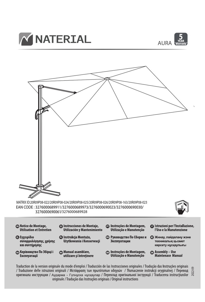
Naterial 20R09P08-022 Assembly-Use-Maintenence Manual

Naterial

Naterial 20R09P08-022 Assembly-Use-Maintenence Manual

FJK home products ABU-10-48&42-6 Assembly instruction

FJK home products

FJK home products ABU-10-48&42-6 Assembly instruction

Sunjoy D-UM004-1 Assembly instructions

Sunjoy

Sunjoy D-UM004-1 Assembly instructions

LDI Spaces SAFCO 4168 instructions

LDI Spaces

LDI Spaces SAFCO 4168 instructions

VIFAH V025-1 user manual

VIFAH

VIFAH V025-1 user manual

BCP SKY5949 instruction manual
BCP

BCP SKY5949 instruction manual

Arboria Heritage Arbor Assembly instructions

Arboria

Arboria Heritage Arbor Assembly instructions

PATIOJOY HW71328 manual

PATIOJOY

PATIOJOY HW71328 manual

Sears GRAND RESORT Osborn Woven D71 M20179 Use and care guide

Sears

Sears GRAND RESORT Osborn Woven D71 M20179 Use and care guide

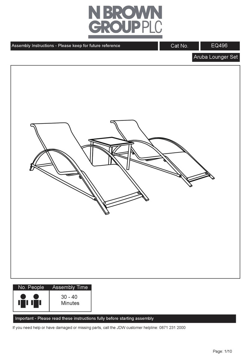
N Brown Group Aruba Lounger Set Assembly instructions

N Brown Group

N Brown Group Aruba Lounger Set Assembly instructions

Haushalt International 62467 Directions for use and safety instructions

Haushalt International

Haushalt International 62467 Directions for use and safety instructions

Umbrosa SPECTRA STRAIGHT Assembly instructions

Umbrosa

Umbrosa SPECTRA STRAIGHT Assembly instructions

Essential Garden 0-02616790-8 owner's manual

Essential Garden

Essential Garden 0-02616790-8 owner's manual

Extremis INUMBRINA Assembly instructions

Extremis

Extremis INUMBRINA Assembly instructions

PATIOJOY HW70624 Instruction booklet

PATIOJOY

PATIOJOY HW70624 Instruction booklet

VONROC GP504 Series Original instructions

VONROC

VONROC GP504 Series Original instructions

MDT-tex H user guide

MDT-tex

MDT-tex H user guide

Extremis Sol+Luna manual

Extremis

Extremis Sol+Luna manual

manuals.online logo
manuals.online logoBrands
  • About & Mission
  • Contact us
  • Privacy Policy
  • Terms and Conditions

Copyright 2025 Manuals.Online. All Rights Reserved.