HARBEN 4018 US Van Pack Manual
Harben Inc.
P.O. Box 2250, Cumming, GA 30028
Toll Free: (800)-327-5387 Tel: (770)-889-9535 Fax: (770)-887-9411
email: sale[email protected]m web: www.harben.com
Operation & Maintenance Manual
Original Instructions
Unit 4018 US Van Pack
903-1314
Section 1 Introduction
Section 2 Scope of Supply
Section 3 Technical Data
Section 4 Operation
Section 5 Routine Maintenance
Section 6 Fault Finding
Section 7 Harben P-Type Pump
Section 8 Circuit Diagrams
Section 9 Engine
Section 10 Parts List / Spares / Auxiliary Components
Section 11 Service Documents
Section 12 Warranty & Certification
Section 13 Health & Safety Manual 903-1308
Read the Health and Safety Manual before
operating any equipment. Failure to do so could
cause serious injury or death.
1
Operation & Maintenance Manual for:
UNIT: Unit 4018 US Van Pack – R/1 (B11238/A)
ISSUE DATE: 6/20
ISSUE No: 6
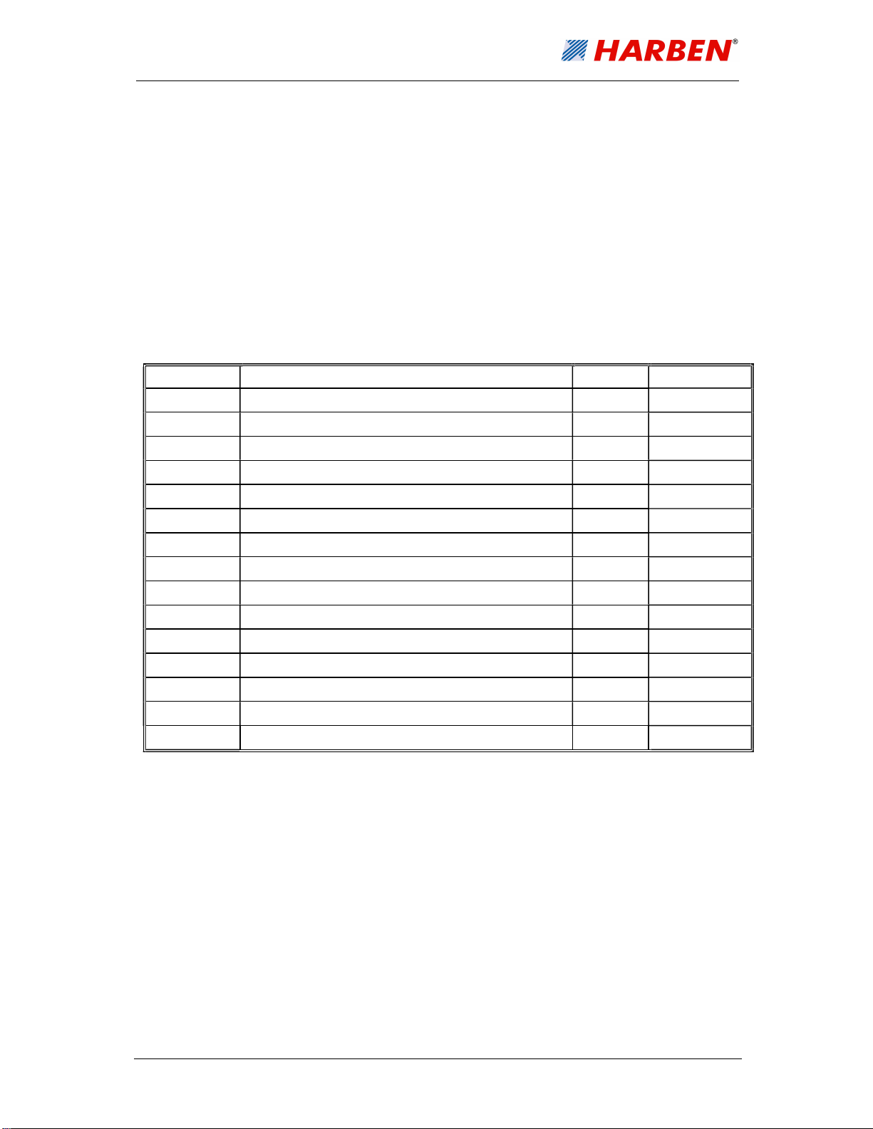
AMENDMENTS
Change Changes Date Signature
1 NEW ADDITION 09/19 JJ
2 UPDATE WARRANTY POLICY 10/19 JJ
3 Minor Changes. Added part number 5/20 GT
4 Added multiple sections. Minor changes 6/20 GT
5 Added Pictures to Anti-Freeze Section 6/20 GT
6 Updated manual to code 6/20 GT

2
Section 1 – Introduction & Contents
1.1.
Contents
SECTION 1 – INTRODUCTION & CONTENTS ....................................................................2
1.1. C
ONTENTS ....................................................................................................................2
1.2. INTRODUCTION ..............................................................................................................5
1.3. SCOPE OF THIS MANUAL ................................................................................................6
1.4. THE VANPACK ...............................................................................................................6
1.5. COMPOSITION OF THIS MANUAL......................................................................................7
SCOPE OF SUPPLY ......................................................................................................8
2.1. SCOPE OF SUPPLY ........................................................................................................8
2.2. PUMP ASSEMBLY ..........................................................................................................8
2.3. DETAILED DRAWINGS ....................................................................................................8
TECHNICAL DATA ...................................................................................................... 11
3.1. TECHNICAL DATA ........................................................................................................ 11
3.1.1. PUMP DATA .............................................................................................................. 11
3.1.2. MAIN COMPONENTS .................................................................................................. 12
3.1.3. ANCILLARIES ............................................................................................................ 12
3.1.4. SERVICES REQUIRED ................................................................................................ 12
3.2. TECHNICAL DESCRIPTION ............................................................................................ 13
3.2.1. PRIMARY COMPONENTS ............................................................................................ 13
3.2.2. ENGINE MONITORING ................................................................................................ 13
OPERATION ................................................................................................................ 14
4.1. OPERATING CONDITIONS ............................................................................................. 14
4.2. DAILY CHECKS ............................................................................................................ 14
4.3. PRE-START CHECKS & PROCEDURES ........................................................................... 14
4.4. CONTROL PANEL LAYOUT AND FUNCTION ...................................................................... 15
4.4.1. CONTROL KEYS ........................................................................................................ 15
4.4.2. TOGGLE SWITCH OPERATION ..................................................................................... 15
4.4.3. SCREEN LAYOUTS ..................................................................................................... 16
4.4.4. RADIO CONTROL LAYOUT ........................................................................................... 18
4.5. RUNNING THE ENGINE (MANUAL MODE)........................................................................ 18
4.6. RUNNING THE ENGINE (RADIO MODE) ........................................................................... 19
4.7. RUNNING THE VANPACK .............................................................................................. 19
4.8. HARBEN
®
JUMP JET .................................................................................................... 20
3
4.9. B
YPASS VALVE OPERATION ......................................................................................... 21
4.10. HOSE REEL WINDING AND UNWINDING ....................................................................... 22
4.11. FROST PRECAUTIONS ................................................................................................ 23
4.11.1. TO ANTI-FREEZE THE MACHINE WITH AN ANTI-FREEZE TANK ....................................... 23
4.11.2. TO DE-ANTIFREEZE THE MACHINE ............................................................................. 24
ROUTINE MAINTENANCE ........................................................................................... 26
5.1. MAINTENANCE PROCEDURES ....................................................................................... 26
5.2. DAILY MAINTENANCE (H&S SECTION 11) ..................................................................... 27
5.3. PUMP LUBRICATING CHART ......................................................................................... 28
5.4. BURST DISCS .............................................................................................................. 29
FAULT FINDING .......................................................................................................... 30
6.1. FAULT FINDING - ELECTRICAL ...................................................................................... 30
6.2. FAULT FINDING - HYDRAULIC ....................................................................................... 31
6.3. PUMP FAULT FINDING .................................................................................................. 32
6.4. SELECTOR FAULT FINDING ........................................................................................... 34
PUMP ........................................................................................................................... 35
CIRCUIT DIAGRAMS ................................................................................................... 36
8.1. WATER CIRCUIT FOR VANPACK ................................................................................. 36
8.2. HYDRAULIC CIRCUIT FOR VANPACK ........................................................................... 36
ENGINE ........................................................................................................................ 37
PARTS LIST / SPARES ............................................................................................. 38
10.1. INTRODUCTION .......................................................................................................... 38
10.2. ORDERING SPARE PARTS .......................................................................................... 38
10.3. ROUTING MAINTENANCE / CONSUMABLE ITEMS ........................................................... 38
10.4. CONSUMABLE COMPONENTS ...................................................................................... 38
10.5. PARTS LIST ............................................................................................................... 39
10.5.1. REMOTE ................................................................................................................... 39
SERVICE DOCUMENTS ............................................................................................ 43
11.1. SERVICE CHECKLIST .................................................................................................. 43
11.2. SERVICE LOGBOOK ................................................................................................... 44
WARRANTY ............................................................................................................... 45

4
12.1. WARRANTY OF NEW PRODUCTS: ................................................................................ 45
12.2. WARRANTY OF MAJOR COMPONENTS: ....................................................................... 45
12.3. LIMITATIONS OF WARRANTY:...................................................................................... 47
This manual suits for next models
1
Table of contents
Popular Cleaning Equipment manuals by other brands


Suevia
Suevia 130.5011 EASYCLEANER Mounting instructions

i-MO
i-MO Öko 2000 user guide

unGer
unGer Hydro Power Ultra UNP01 operating instructions

Black & Decker
Black & Decker BHPC130 Original instructions

Uni-ram
Uni-ram UG5000E operating manual

Axi
Axi MTC HC-300 Installation, operating and maintenance manual