manuals.online logo
Brands
  1. Home
  2. •
  3. Brands
  4. •
  5. Hardi
  6. •
  7. Farm Equipment
  8. •
  9. Hardi SARITOR Self Propelled Assembly instructions

Hardi SARITOR Self Propelled Assembly instructions

SARITOR Self Propelled
Operator Instruction Manual
67000304- 201
HAU - 09.2009
www.hardi.com.au
We congratulate you for choosing a HARDI plant protection product. The reliability and efficiency of this product
depends upon your care. The first step is to carefully read and pay attention to this instruction book. It contains
essential information for the efficient use and long life of this product.
As this instruction book covers all versions of the equipment, including all hydraulic boom versions, and all
operating units, please pay attention to the paragraphs dealing precisely with your model.
This book is not designed to be a maintenance manual, its main purpose is to supply operational information and
is to be read in conjunction with the “Spray Technique” book and any other manuals supplied with your sprayer.
Illustrations, technical information and data in this book are to the best of our belief correct at the time of printing.
As it is HARDI Australia policy to improve our products, we reserve the right to make changes in design, features,
accessories, specifications and maintenance instructions at any time and without notice.
HARDI Australia is without any obligation in relation to implements purchased before or after such changes.
HARDI Australia cannot undertake any responsibility for possible omissions or inaccuracies in this publication,
although everything possible has been done to make it complete and correct.
As this instruction book covers more models and features or equipment, which are available in certain countries
only, please pay attention to paragraphs dealing with precisely your model.
Published by HARDI Australia
Table of Contents
TOC. 1
Welcome
Section 1
Welcome Message 2
Safety
Section 2
Operator Safety1
Introduction
Safety Alert Icons
Spray Drift
Mechanical Safety
Disposal of Chemical Containers
Chemical Safety
Safety Equipment
Contaminated Clothing and Equipment
Australian Safety Standards
Chemical Information
Sprayer Safety
Operations
Service and Maintenance
Engine Safety
Engine Operation
Electrical Safety
During Sprayer Use
Operation of Electrical Components
Table of Contents
TOC. 2
Description
Section 3
Introduction 1
General Info
View 1
View 2
Identification Plates
Roadworthiness
Chassis
Tanks
Further documents
In-Cab Controls and Features 5
Electronic Control Units
AgLeader Insight Display
AgLeader DirectCommand Application
Saritor Section Control Grip
Right Side Controls
The Cantrak Engine Monitor
The Tri Display
The Tri display (Fuel Computer Modes)
The Quad Display
“A” Pillar Monitors/Gauges
Fuel Gauge
Digital Display
Ancillary Equipment
Auxiliary Power Outlet
Power Strip Outlets
Cabin Access Ladder
Night Spraying Lights
External Features
Main Tank Level Indicator
Safety Locker
Liquid System
Pump
Standard
Pump Drive
Control Box
Filters
2 inch and 3 inch Quick Couplers
Turbofill
EFC Section valves
Table of Contents
TOC. 3
Boom
Boom configurations
Boom Terminology
Boom Operators Manual
Boom Lock-In Mechanism
Boom Lift Accumulators
Norac Boom Auto Height Control
Sprayer Set-Up
Section 4
Introduction 1
Safety
Before operating the sprayer
Start Up
SARITOR 4800 AgLeader Setup Process 3
Home Icon
Tool Icon
Grower Field Management
Create Grower
Input Season details
Input Field data
Input Operator data
Application Setup
Configuration
Vehicle
Implement
Controller
Product
Console Setup
GPS Guidance
Field Notes
Notes Icon
Run Icon
Driver Accessory Adjustments 5
Seat Suspension and Adjustment
Adjusting Armrest
Adjust Left Hand Armrest
Steering Column Tilt
Telescopic Steering Wheel
Radio/Cassette/CD
Table of Contents
TOC. 4
Sprayer Operation
Section 5
Transporting 1
General
Transporting Sprayer On Equipment Trailer
Towing
Track Width
Cabin Switches and Controls 2
Vehicle Lighting Switches
Hazard Lights (Switch A)
Road Lights (Switch B)
Field Lights (Switch C) - 2 position switch
Work Lights (Switch D)
Turn Signals
Heater and Air Conditioner Controls
Storage Compartments
Cabin Ingress / Egress
Cab door lock and handle
Interior door handle
Emergency Exit
Seat Belts
Overhead Console
Turn Signals On
Low Fuel
Park Brake
Wait To Start
Transmission Temperature
Hydraulic Oil Temperature
Voltage
Check Transmission
Low Brake Pressure
Stop Engine
Windshield Wiper/Washer Switch
Cab Interior Light
Track Width Alteration - Leg Widening
Horn Button
Brake Pedal
Engine Speed Accelerator Pedal
Differential Lock Pedal
Ignition Switch
Console Panel Controls 9
Transmission Speed and Direction Selector
Park Brake Control Knob
Table of Contents
TOC. 5
Product Pump ON/OFF Switch
Agitation ON/OFF Switch
Rinse Mode Selector Knob
AgLeader Insight Display
Saritor Section Grip Controller
Engine Speed Control handle
Common Operations 14
Re-Fuelling
FTZ FORCE Boom control
Unfolding procedure
Folding procedure
Alternative boom width
Boom support wheels (Optional)
Adjustment of EFC operating unit 16
To check the EFC operating unit
Liquid system 17
Filling of water
Filling - Main Tank
Filling - Rinse Tank
Filling the clean water tank
Chemical induction by HARDI TurboFiller 19
Turbo Filler Manifold Controls
Chemical container cleaning lever
TurboDeflector valve
TurboFiller suction valve
Turbo Filler - PH6 Scienco Pump
Agitation 21
Variable Agitation control
Agitating Product Tank
Agitation before re-starting spraying
Table of Contents
TOC. 6
Filters 22
Cyclone Filter
Return Valve
Position A
Position B
Position C
Multi Section Filter
Cleaning of filters
In-Field Spraying Operation 23
Cleaning
Introduction
Cleaning Guidelines
Rinse System
Spray Mode
Tank Rinse Mode
Tank Empty Mode
Boom Rinse Mode
Rinsing boom and fluid system
Rinsing the pump and spray lines
Rinsing the entire liquid system
De-contamination27
Introduction
De-contamination agents
Decontamination
Tank rinsing
Using the drain valve
Maintenance
Section 6
Introduction1
Maintenance procedures
Before you get started
Spare parts
Lubrication
General info
Table of Contents
TOC. 7
Recommended lubricants 3
BALL BEARINGS
SLIDE BEARINGS
OIL LUB. POINTS
“O” Ring Seals
Boom lubrication plan
Regular Interval Servicing 4
10 & 50 Hourly Servicing
- Nozzle filters
- Cyclone & MultiSection filters
To service the Cyclone filter
To reassemble
Occasional Maintenance 6
General info
Level Indicator Cord Replacement
Boom Tube Fittings
Shock Absorbers
Wear bushing replacement
Tyre & Wheel Fitting
Tyre Fitting
Wheel Fitting
EFC distribution valve service
Section valves removal procedure
To remove the EFC valves proceed as follows
Section valves service procedure
EFC Dis-assembly procedure
Cone check/renewal for Pressure Regulation
Boom adjustment and service
Changing bulbs (conventional work lights)
Off-season storage 11
Off-season storage program
Preparing the sprayer for use after storage
Table of Contents
TOC. 8
Checks & Adjustments 12
General info
Boom Adjustments
Level indicator adjustment
Front Brake Caliper - If Fitted
Removal
Reassembly
Bleeding The Brakes
Rear Differential Brake Caliper
Removal
Reassembly
Bleeding The Brakes
Steering Cylinder Phasing
Steering Toe-In Adjustment
Transmission Fluid Level
Rear Differential
Oil Level Check
Change Differential Oil
Rear Drop Box (48" Clearance Machines)
Oil Level Check
Change Drop Box Oil
Differential Output Shaft Nuts
Steering Cylinder Ball Joints
Changing Hydraulic Reservoir Oil
Hydraulic Oil filter
Check Hydraulic Hose and Fitting Condition
Check Hydraulic Cylinders
Air Compressor
Air Tank & Air compressor inspection
Raising and Lowering Hood
To Raise Hood
To Lower Hood
Heat Exchangers
Cooling Package Cleaning
Engine Coolant
Coolant Level Check
Add Coolant
13 Spline Cooling Coupler
Hydraulic System Maintenance 25
General Information
Hydraulic System Cleanliness
Table of Contents
TOC. 9
Engine Maintenance 26
General Information
Engine Oil and Filter
Fuel Filters
Primary Fuel Filter (Water Separator)
Secondary Fuel Filter
Drive Shaft Universal Joints
Front and Rear Axle Wear Pads
Front Axle King Pins
Front Wheel Hub Bearings
Engine Air Cleaner Filters (Oval)
Storage Tray / Recirculation Filter
Engine Data Link Connector
Maintenance Schedule 30
Fault Finding
Section 7
Operational Problems 1
Introduction
Prevention
Sensors 4
Introduction
Sensor types
Pressure Transducer and Flow Sensor
Flow Sensor Inspection
Engine Trouble Shooting 5
Engine Fault Codes
DirectCommand TroubleShooting Guide 17
Table of Contents
TOC. 10
Technical Specifications
Section 8
General A75 Specifications 1
Dimensions
Overall Dimensions
Weight
Conversion factors: Metric to Imperial units
Filter mesh specifications
Recommended Tyre Pressures
Recommended Lubricants & Filters
Recommended Coolant
Electrical connections for InSight 4
EFC 5
EFC - Fluid PCB
Sprayer hydraulics 7
Hydraulic Oil Recommendations
Typical Characteristics
AutoSteer Hose Connections 8
AgLeader System Connections Overview 9
Joystick Interface Connections 15
Tightening Hydraulic Fittings 16
Tightening O-Ring Fittings
Tightening Flare Type Fittings
Torque Specifications 17
Spare part information 18
HARDI spare parts pages
Materials and recycling 18
Disposal of the sprayer
Table of Contents
TOC. 11
Warranty
Section 9
Warranty policy & conditions 1
Risk Assessment
Section 10
Entanglement 1
Cutting, Stabbing, Puncturing or Striking 1
Shearing 1
Crushing 2
Electrical 3
Explosion 3
Friction 3
Pressure 4
Slips, Trips & Falls 4
Ergonomics 5
Suffocation 5
High Temperature or Fire 5
Other Hazards 6
Condition / Stability 6
Environment 7
Abnormal Situations 7
Systems of Work 8
Table of Contents
TOC. 12
1 - Welcome
1. 1
SARITOR
Operator Instruction Manual
67000304- 201
HAU - 09.2009
HARDI Australia
Cross Keys Road Cavan
South Australia
1 - Welcome
1. 2
Welcome Message
To our valued customer:
Congratulations on your purchase and thank you for choosing the HARDI “SARITOR” Self Propelled Sprayer. This
“Operator Instruction Manual” covers the Safety, Operation and Maintenance procedures for the 4800 Litre model,
and is to be read in conjunction with the “Boom”and “Spray Controller” manuals supplied with your sprayer.
This book is not designed to be a maintenance manual, its main purpose is to supply operational information and
is to be read in conjunction with the “Spray Technique” book and any other manuals supplied with your sprayer.
±WARNING: Any persons intending to use this equipment, or any of it’s parts or systems must read and
understand these publications, in addition to any related material, paying close attention to the safety
warnings prior to operation.
In addition, all operators must be of a suitable age, have undergone appropriate training and hold correct licenses
where applicable, as required by state and federal law. The safety sections and warnings in this publication and all
related material must be thoroughly read and understood before attempting to operate this equipment.
€DANGER: Failure to comply with the above may result in personal injury, death or damage to the
equipment,property, crops or the environment.
μAttention: The technical data contained herein is to the best knowledge of HARDI Australia Pty Ltd correct at the time
of publishing. HARDI Australia Pty Ltd reserves the right to make changes in design, features, accessories,
specifications and instructions at any time without prior notice and is without obligation in relation to products
purchased before or after such changes and assumes no responsibility for any errors, inaccuracies or omissions.
μAttention: HARDI Australia accepts no responsibility for damage to property, livestock, persons or structures, or loss
of income as a result of operation by owners/operators of HARDI products.
Please visit our web site at:
www.hardi.com.au
for more information about research and development, our product range, spraying techniques and crop
protection. For sales, service and spare parts information contact your local HARDI dealer.
Copyright: Design, text, illustrations and layout in this manual are produced and published by HARDI Australia Pty
Ltd and are protected by copyright law. Copyright © June 2009 HARDI Australia Pty Ltd.
2 - Safety
2. 1
Operator Safety
Introduction
This manual contains safety information which could prevent crop damage, personal injury or death. It is
compulsory that all operators intending to use this equipment read and understand this manual and related
literature. Safety information in each section must be read carefully, and if any doubt contact your HARDI dealer
for further information.
Safety Alert Icons
Safety information in this manual is highlighted by the following icons according to the level of potential risk:
€DANGER: This indicates the highest level of hazard alert. Failure to comply with the information contained
here could result in personal injury or death.
±WARNING: This indicates that mandatory action is required. Failure to comply with the information
contained here could result in damage to crops, the equipment and/or the environment.
μAttention: This indicates practical information regarding safe and effective use of the equipment and its systems.
÷Note: This indicates general information that can provide the reader with a higher level of understanding.
Spray Drift
±WARNING: Serious crop damage can occur as a result of spray drift. Certain climatic conditions can increase
the risk of spraydrift onto neighbouring crops.
Although calibration information is provided in the Spraying Techniques Manual it is vitally important that you
read the chemical manufacturer’s recommendations for the correct use of their product.The manufacturers label
will also state the products limitations and warnings.
Wind speed, temperature, humidity and chemical properties should all be considered when determining if
conditions are suitable for spraying. Contact your local Department of Primary Industries for details of relevant
publications explaining the risks and how best to minimise them. It is the responsibility of the sprayer operator to
make sure that the spraying conditions are suitable for the application of the chemical to be used.
±WARNING: After changing chemicals or crops it is essential that the entire sprayer be flushed. This includes
disconnecting hoses from the filters and pressure relief valve and cleaning residue and sediment in the
hoses, valves and filters. Failure to do so may potentially lead to serious crop damage.
μAttention: Remove and store safety wear and clothing after spraying to prevent contamination of the cabin. Dispose
of, or clean appropriately. If poisoning occurs identify the chemicals and seek medical advice urgently.
μAttention: HARDI or its personnel accepts no responsibility for spray drift damage.
2 - Safety
2. 2
Mechanical Safety
€DANGER: Never operate any part of the equipment if any of it’s components or safety shields are damaged.
Never service or repair the equipment while it’s operating and replace all safety devices and shields after
service procedures.
€DANGER: Always de-pressurise the equipment and disconnect the power after each use and before
servicing. make sure all hydraulics are in the recommended position. Do not walk under any part of the
sprayer or the boom unless it is properly secured.
€DANGER: Never attempt to enter a tank or allow some one else to do so for any reason.
€DANGER: No persons are allowed in the operations area of the sprayer. Keep unauthorised persons and
children away from the equipment at all times. Do not allow any one to ride on the equipment while it is
operating.
€DANGER: Do not exceed the max. recommended RPM for any part of this equipment.
€DANGER: Local laws may require operators to be certified before using spray equipment and some
chemicals. Consult your local authorities before commencing operation.
±WARNING: When using an arc welder disconnect any power leads to the sprayer prior to welding and remove
any flammable or explosive material from the area. Do not weld on chassis, engine, hydraulic, or electrical
components.
±WARNING: Although every effort has been made to include as much safety information as practical, it is
impossible to anticipate every hazardous scenario. It is therefore the responsibility of the operator to
exercise safe operating practices.
±WARNING: This equipment is intended for the application of crop protection chemicals and liquid fertilisers
only. HARDI Australia does not authorise or endorse it’s use for any other purpose.
μAttention: The drivers seat is the only intended working place during operation. One passenger may ride in the ‘dicky
seat’ under supervision of the driver. Use only for training, fault diagnosis or similar - Do not use as a regular passenger
seat.
Disposal of Chemical Containers
Please note that in addition to normal safe operating practices, and in the interests of a cleaner and safer
environment HARDI Australia supports the “drumMUSTER” chemical drum recycling program:
•Rinse empty drums immediately after use.
•Remove lids to allow drums to dry completely.
•Recycle with “drumMUSTER”
±WARNING: Used chemical containers pose a severe threat to persons, animals and the environment. Before
disposal, contact the Environmental Protection Authority or the Department of Primary Industries in your
area for more information.
2 - Safety
2. 3
Chemical Safety
€DANGER: Avoid risk of chemical contamination. Always read chemical labels and pressure test the
equipment with clean water prior to filling. Never eat, drink or smoke when spraying or working with
contaminated equipment.
€DANGER: Never drink water from any of the sprayer's tanks.
€DANGER: Never assume that the contents of the ‘clean water’tank is safe to drink
€DANGER: Chemical contamination poses a serious health risk. It is the responsibility of the operator to make
sure safe work practices are observed and correct safety equipment and clothing is used.
Safety Equipment
Depending on the type of chemical used, some or all of the following protective
clothing and equipment will be required (see diagram to right).
Contaminated Clothing and Equipment
Contaminated clothing should be carefully removed, safely
isolated and then appropriately laundered or disposed of, taking
care not to contaminate the inside of the cabin. Tools and
equipment used must also be safely isolated and carefully washed
and decontaminated.
Australian Safety Standards
Protective clothing and equipment must conform to Australian
Safety Standards and must always be used when handling
chemicals, operating the sprayer and during the cleaning and
decontamination process.
Chemical Information
Always read the chemical manufacturer’s labels as they contain
critical information about your safety and the environment. Always consider the environment when disposing of
chemical residue (see section on decontamination). Chemical labels are registered by the National Registration
Authority. Laws vary from state to state regarding the purpose for which a chemical may be used so consult your
local authorities.
€DANGER: Agricultural chemicals can be dangerous. Always read chemical labels and carefully follow safety
recommendations to the letter.
μAttention: Please refer to the chapter on “Cleaning and De-contamination”in the Operation section of this manual for
further information.
1. Hearing Protection
2. Eyes and Face Protection
3. Respirator
4. Chemical Resistant Overalls
5. Chemical Resistant Gloves
6. Chemical Resistant Boots
1
2
3
4
5
6
2 - Safety
2. 4
Sprayer Safety
Operations
For your safety:
€DANGER: Secure the discharge lines before starting the pump. An insecure line may whip causing personal
injury and/or property damage.
€DANGER: Never operate this vehicle on public roads at high speeds with product in the product tank.
Driving at high speeds with product in the tank will overload the tyres, causing tyre failure leading to loss of
control. Losing control will result in death or serious injury.
€DANGER: Do not use these pumps for pumping water or other liquids for human or animal consumption.
±WARNING: Do not pump at pressures higher than the maximum recommended pressure.
±WARNING: Empty all product from the product tank before leaving the field. Do not attempt to drive this
vehicle at high speeds with product in the tank. Fill product tank once you have reached the area of
operation.
±WARNING: Turn on the hazard lights and the road lights before entering onto a public road. Keep them on
while travelling on the road. Operators should obtain and read relevant regulations and laws for the state or
territory that they intend to operate in.
±WARNING: Check hoses for wear or worn condition before each use. Make certain that all connections are
tightly secured.
μAttention: Periodically inspect the product pump and the system components. Perform routine maintenance as
required.
μAttention: Clean off all hazard and road lights when going from the field to the road.
Service and Maintenance
For your safety:
€DANGER: Release all pressure within the system before servicing any component.
€DANGER: Drain all fluids from the system before servicing any component. Flush with water.
±WARNING: Disconnect power before servicing.
±WARNING: Use only pipe, hose and fittings rated for the maximum psi rating of the pump.

Other Hardi Farm Equipment manuals

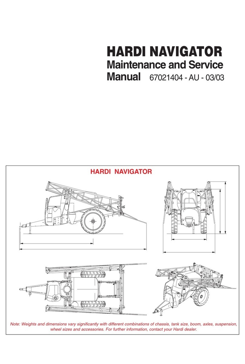
Hardi COMMANDER DELTA FORCE User manual

Hardi

Hardi COMMANDER DELTA FORCE User manual

Hardi Master Plus User manual

Hardi

Hardi Master Plus User manual

Hardi COMMANDER TWIN FORCE User manual

Hardi

Hardi COMMANDER TWIN FORCE User manual

Hardi AEON CENTURA DELTA FORCE User manual

Hardi

Hardi AEON CENTURA DELTA FORCE User manual

Hardi ALPHA EVO II EcoDrive User manual

Hardi

Hardi ALPHA EVO II EcoDrive User manual

Hardi ZENIT A750 User manual

Hardi

Hardi ZENIT A750 User manual

Hardi Commander Plus SPC Series User manual

Hardi

Hardi Commander Plus SPC Series User manual

Hardi ALPHA evo ALU-TWIN FORCE User manual

Hardi

Hardi ALPHA evo ALU-TWIN FORCE User manual

Hardi JAZZ User manual

Hardi

Hardi JAZZ User manual

Hardi TWIN BOOM User guide

Hardi

Hardi TWIN BOOM User guide

Hardi ALPHA evo EcoDrive TWIN FORCE User manual

Hardi

Hardi ALPHA evo EcoDrive TWIN FORCE User manual

Hardi Navigator Series Manual

Hardi

Hardi Navigator Series Manual

Hardi ZATURN User manual

Hardi

Hardi ZATURN User manual

Hardi DEMOUNT User manual

Hardi

Hardi DEMOUNT User manual

Hardi 3500 EXPLORER User manual

Hardi

Hardi 3500 EXPLORER User manual

Hardi COMMANDER DELTA FORCE User manual

Hardi

Hardi COMMANDER DELTA FORCE User manual

Hardi TERRA FORCE BOOM User manual

Hardi

Hardi TERRA FORCE BOOM User manual

Hardi MERCURY 2000 User manual

Hardi

Hardi MERCURY 2000 User manual

Hardi COMMANDER Classic PRO User manual

Hardi

Hardi COMMANDER Classic PRO User manual

Hardi SMARTCOM ISOBUS UT SW A.2.2 Series User manual

Hardi

Hardi SMARTCOM ISOBUS UT SW A.2.2 Series User manual

Hardi MASTER plus HYS User manual

Hardi

Hardi MASTER plus HYS User manual

Hardi NAVIGATOR 4000 User manual

Hardi

Hardi NAVIGATOR 4000 User manual

Hardi RANGER 2500 TR2 User manual

Hardi

Hardi RANGER 2500 TR2 User manual

Hardi COMMANDER TWIN FORCE User manual

Hardi

Hardi COMMANDER TWIN FORCE User manual

Popular Farm Equipment manuals by other brands

Toro VS-400 Operator's manual

Toro

Toro VS-400 Operator's manual

Lesco SC180L owner's manual

Lesco

Lesco SC180L owner's manual

Hillco JS7020 Operator's manual

Hillco

Hillco JS7020 Operator's manual

McHale Fusion 2 Operator's instruction manual

McHale

McHale Fusion 2 Operator's instruction manual

Pottinger VITASEM 250 Mounting instructions

Pottinger

Pottinger VITASEM 250 Mounting instructions

Wylie MAX-LITE II Operator's & parts manual

Wylie

Wylie MAX-LITE II Operator's & parts manual

Kubota BH92 Operator's manual

Kubota

Kubota BH92 Operator's manual

Kongskilde Z 8805 Operator's manual

Kongskilde

Kongskilde Z 8805 Operator's manual

Harvest TEC 442P owner's manual

Harvest TEC

Harvest TEC 442P owner's manual

Titan Attachments LW48BUCKET Operator's manual

Titan Attachments

Titan Attachments LW48BUCKET Operator's manual

Hoegger Home Farm Products Milking System Training Series manual

Hoegger Home Farm Products

Hoegger Home Farm Products Milking System Training Series manual

Simba X-Press operating instructions

Simba

Simba X-Press operating instructions

GREAT PLAINS 6000 Series Operator's manual

GREAT PLAINS

GREAT PLAINS 6000 Series Operator's manual

Vicon Andex 1104 Assembly instructions

Vicon

Vicon Andex 1104 Assembly instructions

GREAT PLAINS LC25 FIELD ADJUSTMENT GUIDE

GREAT PLAINS

GREAT PLAINS LC25 FIELD ADJUSTMENT GUIDE

Stihl AHK 701 instruction manual

Stihl

Stihl AHK 701 instruction manual

ATI Technologies Micro M5 manual

ATI Technologies

ATI Technologies Micro M5 manual

Veris U3 troubleshooting guide

Veris

Veris U3 troubleshooting guide

manuals.online logo
manuals.online logoBrands
  • About & Mission
  • Contact us
  • Privacy Policy
  • Terms and Conditions

Copyright 2025 Manuals.Online. All Rights Reserved.