GSi PNEG-2113 User manual

PNEG-2113
36' Recessed Dura-Lok Plank
and Support Manual
Owner’s Manual
PNEG-2113
Version: 3.0
Date: 10-15-20

2 PNEG-2113 36' Recessed Dura-Lok Plank and Support Manual
All information, illustrations, photos, and specifications in this manual are based on the latest
information available at the time of publication. The right is reserved to make changes at any
time without notice.

Table of Contents
PNEG-2113 36' Recessed Dura-Lok Plank and Support Manual 3
Contents
Chapter 1 Introduction ..........................................................................................................................................4
Chapter 2 Safety .....................................................................................................................................................5
Safety Guidelines .................................................................................................................................. 5
Cautionary Symbols Definitions ............................................................................................................ 6
Safety Cautions ..................................................................................................................................... 7
Safety Sign-Off Sheet ........................................................................................................................... 9
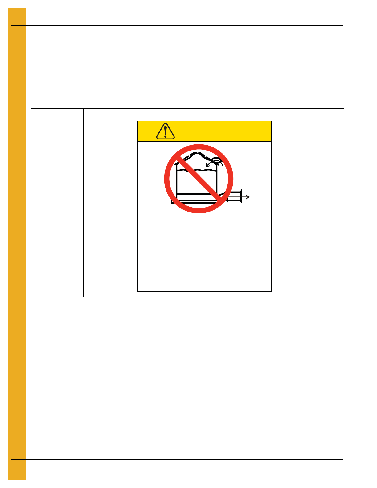
Chapter 3 Decals ..................................................................................................................................................10
Chapter 4 Monorail Installation ..........................................................................................................................12
Fan Placement Diagram ..................................................................................................................... 12
Tie Bar Detail ...................................................................................................................................... 13
Tie Strap Detail ................................................................................................................................... 14
Assembling Legs to Rail ...................................................................................................................... 15
Monorail Splice Detail ......................................................................................................................... 17
Outer Perimeter Rail Details ............................................................................................................... 19
Chapter 5 Flooring - Planks ................................................................................................................................20
Flashing Installation ............................................................................................................................ 20
Center Well Assembly Details ............................................................................................................. 22
Intermediate Well Assembly Details .................................................................................................... 23
Chapter 6 Layouts ................................................................................................................................................24
36'-10" Rail Spacing Layout ................................................................................................................ 24
36'-10" Monorail Spacing Layout ........................................................................................................ 25
36'-16" Rail Spacing Layout ................................................................................................................ 26
36'-16" Monorail Spacing Layout ........................................................................................................ 27
36'-17" Rail Spacing Layout ................................................................................................................ 28
36'-17" Monorail Spacing Layout ........................................................................................................ 29
36'-18" Rail Spacing Layout ................................................................................................................ 30
36'-18" Monorail Spacing Layout ........................................................................................................ 31
36'-20" Rail Spacing Layout ................................................................................................................ 32
36'-20" Monorail Spacing Layout ........................................................................................................ 33
36'-22" Rail Spacing Layout ................................................................................................................ 34
36'-22" Monorail Spacing Layout ........................................................................................................ 35
36'-26" Rail Spacing Layout ................................................................................................................ 36
36'-26" Monorail Spacing Layout ........................................................................................................ 37
36' Recessed Floor Bundle Layout ..................................................................................................... 38
36' Recessed Floor Plank Layout ........................................................................................................ 39
Chapter 7 Warranty ..............................................................................................................................................41

4 PNEG-2113 36' Recessed Dura-Lok Plank and Support Manual
1. Introduction
READ THIS MANUAL carefully to learn how to properly use and install equipment. Failure to do so could
result in personal injury or equipment damage.
INSPECT the shipment immediately upon arrival. The customer is responsible for ensuring that all
quantities are correct. The customer should report and note any damage or shortage on the bill of
lading to justify their claim to the transport company.
THIS MANUAL SHOULD BE CONSIDERED a permanent part of your equipment and should be easily
accessible when needed.
This warranty provides you the assurance that the company will back its products when defects appear
within the warranty period. In some circumstances, the company also provides field improvements, often
without charge to the customer, even if the product is out of warranty. Should the equipment be abused,
or modified to change its performance beyond the factory specifications, the warranty will become void
and field improvements may be denied.

PNEG-2113 36' Recessed Dura-Lok Plank and Support Manual 5
2. Safety
Safety Guidelines
Safety guidelines are general-to-specific safety rules that must be followed at all times. This manual is
written to help you understand safe operating procedures and problems that can be encountered
by the operator and other personnel when using this equipment. Read and save these instructions.
As owner or operator, you are responsible for understanding the requirements, hazards, and precautions
that exist and to inform others as required. Unqualified persons must stay out of the work area at all times.
Alterations must not be made to the equipment. Alterations can produce dangerous situations resulting in
SERIOUS INJURY or DEATH.
This equipment must be installed in accordance with the current installation codes and applicable
regulations,whichmustbecarefullyfollowed in allcases.Authorities having jurisdictionmustbe consulted
before installations are made.
When necessary, you must consider the installation location relative to electrical, fuel and water utilities.
Personnel operating or working around equipment must read this manual. This manual must be
delivered with equipment to its owner. Failure to read this manual and its safety instructions is a misuse
of the equipment.
ST-0001-4

2. Safety
6PNEG-2113 36' Recessed Dura-Lok Plank and Support Manual
Cautionary Symbols Definitions
Cautionary symbols appear in this manual and on product decals. The symbols alert the user of potential
safety hazards, prohibited activities and mandatory actions. To help you recognize this information, we
use the symbols that are defined below.
DANGER
WARNING
CAUTION
NOTICE
This symbol indicates an imminently hazardous situation
which, if not avoided, will result in serious injury or death.
This symbol indicates a potentially hazardous situation
which, if not avoided, can result in serious injury or death.
This symbol indicates a potentially hazardous situation which,
if not avoided, can result in minor or moderate injury.
This symbol is used to address practices not related to
personal injury.
This symbol indicates a general hazard.
This symbol indicates a prohibited activity.
This symbol indicates a mandatory action.
ST-0005-2

2. Safety
PNEG-2113 36' Recessed Dura-Lok Plank and Support Manual 7
Safety Cautions
Use Personal Protective Equipment
Eye
Protection
Hearing
Protection
Hand
Protection
Head
Protection
Respiratory
Protection Foot
Protection
Fall
Protection
• Use appropriate personal protective equipment:
• Wear clothing appropriate to the job.
• Remove all jewelry.
• Tie long hair up and back.
ST-0004-1
Follow Safety Instructions
• Carefully read all safety messages in this manual and
safety signs on your machine. Keep signs in good
condition. Replace missing or damaged safety signs.
Be sure new equipment components and repair parts
include the current safety signs. Replacement safety
signs are available from the manufacturer.
• Learn how to operate the machine and how to use
controls properly. Do not let anyone operate without
instruction.
• If you do not understand any part of this manual or
need assistance, contact your dealer.
ST-0002-1

2. Safety
8PNEG-2113 36' Recessed Dura-Lok Plank and Support Manual
Maintain Equipment and Work Area
• Understand service procedures before doing work. Keep area
clean and dry.
• Never service equipment while it is operating. Keep hands, feet,
and clothing away from moving parts.
• Keep your equipment in proper working condition. Replace worn
or broken parts immediately.
ST-0003-1
Prevent Roof Damage Due to Vacuum Pressure
• Roof damage can result from excessive vacuum or internal
pressure from fans or other air moving systems. The manufacturer
does not warrant this type of roof damage.
• Adequate ventilation or “makeup air” devices must be provided
for all powered air handling systems.
• The manufacturer does not recommend the use of downward
flow systems (suction).
• Severe roof damage can result from any blockage of air passages.
• Operating fans during high humidity or cold weather conditions can
cause air exhaust or intake ports to freeze.
ST-0028-2
Sharp Edge Hazard
• This product has sharp edges, which can cause serious injury.
• To avoid injury, handle sharp edges with caution and always use
proper protective clothing and equipment.
ST-0036-2

2. Safety
PNEG-2113 36' Recessed Dura-Lok Plank and Support Manual 9
Safety Sign-Off Sheet
Below is a sign-off sheet that canbe used to verify that all personnel have read and understood the safety
instructions. This sign-off sheet is provided for your convenience and personal record keeping.
Date Employee Name Supervisor Name
ST-0007

10 PNEG-2113 36' Recessed Dura-Lok Plank and Support Manual
3. Decals
The safety decals on your equipment are safety indicators which must be carefully read and understood
by all personnel involved in the installation, operation, service and maintenance of the equipment.
To replace a damaged of missing decal, contact us to receive a free replacement.
GSI Decals
1004 E. Illinois St.
Assumption, IL. 62510
Phone: 1-217-226-4421
Location Decal # Decals Description
Located next to
aeration system. DC-969 Caution Vacuum
Pressure
Excessive vacuum (or pressure) may
damage roof. Use positive aeration
system. Make sure all roof vents are
open and unobstructed. Start roof
fans when supply fans are started.
Do not operate when conditions exist
that may cause roof vent icing.
DC-969
CAUTION
GSI Group, Inc. 217-226-4421

3. Decals
PNEG-2113 36' Recessed Dura-Lok Plank and Support Manual 11
Location Decal # Decals Description
On bin door
covers DC-GBC-1A Warning Keep Clear
of Augers
On bin door
covers DC-GBC-2A Warning Unload
Instructions
Failure to heed these warningsFailure to heed these warnings
could result in serious injury, death,could result in serious injury, death,
structural damage or collapse of tank.structural damage or collapse of tank.
DC-GBC-2ADC-GBC-2A
UNLOADING INSTRUCTIONS:UNLOADING INSTRUCTIONS:
1. Use CENTER FLOOR OUTLET ONLY until NO grain1. Use CENTER FLOOR OUTLET ONLY until NO grain
remains above this outlet.remains above this outlet.
2. Side floor outlets to be used ONLY when above2. Side floor outlets to be used ONLY when above
condition is satisfied.condition is satisfied.
3. Lock all side floor outlets to avoid accidental3. Lock all side floor outlets to avoid accidental
premature use.premature use.
4. See manufacturers instructions for proper use of4. See manufacturers instructions for proper use of
factory supplied sidedraw (wall) discharge systems.factory supplied sidedraw (wall) discharge systems.
WARNING
GSI GROUP, INC. 217-226-4421
Rotating flighting could
kill or dismember.
Flowing material could
trap and suffocate.
Crusted material could
collapse and suffocate.
Keep clear of all augers.
DO NOT ENTER this bin!
If you must enter the bin:
1. Shut off and lock out all power.
2. Use a safety harness and safety line.
3. Station another person outside the bin.
4. Avoid the center of the bin.
5. Wear proper breathing equipment or respirator.
Failure to heed these
warnings could result in
serious injury or death.
DC-GBC-1A
GSI GROUP, INC. 217-226-4421
WARNING

4. Monorail Installation
PNEG-2113 36' Recessed Dura-Lok Plank and Support Manual 13
Tie Bar Detail
1. Locate the tie bars between the rails. (Spaced evenly throughout the system.)
NOTE: Tie bars are to be placed at the end of monorail, at each splice and in the middle of the rail
if it is over 16' long. (Not necessarily evenly spaced.) Rail spacing details on Pages 26-36,
detail tie bar placements in each layout.
2. A single #10 x 5/8" self-drilling screws may be used to fasten the tie bars at each end to the rails
as necessary. (See Figure 4B.)
Figure 4B Tie Bar Detail
3. Tie bars should overlap and connect each rail to the next rail. Tie bars should be located along
each side of a rail splice and around the perimeter of the bin, no more than 6" from the end of the rail.
(See Figure 4C.)
Figure 4C Tie Bar Dimension Detail

4. Monorail Installation
14 PNEG-2113 36' Recessed Dura-Lok Plank and Support Manual
Tie Strap Detail
1. Tie straps should be used when a tie bar cannot be used to connect rails together due to special
spacing of monorail. Tie strap should be connected to all three rails using self-drilling screws.
(See Figure 4D.)
2. Tie straps are to be located in the same places as a tie bar would be used.
NOTE: Some tie straps will be used to support center well and intermediate well assembly.
(See Figure 5D on Page 22 and Figure 5E on Page 23.)
Figure 4D Strap Detail

4. Monorail Installation
PNEG-2113 36' Recessed Dura-Lok Plank and Support Manual 15
Assembling Legs to Rail
1. Place two corners of the monorail leg into the rails as shown.
2. By twisting the leg it will spread the rail enough to get the other corners inside.
3. The leg can then be pushed down into the rail until the tabs lock it into place. (See Figure 4E.)
Figure 4E Assembly Leg Rail
See chart on Page 16.
Spacing depends on
eave height.

4. Monorail Installation
16 PNEG-2113 36' Recessed Dura-Lok Plank and Support Manual
Monorail “Rail and Leg Spacing”/“Full Floor Leg Quantity” for Recessed 36' Bin Diameter
4.00"
Ring 2.66" Ring Eave Height (ft.) Rail Spacing Reference
Page Leg Spacing Leg Qty
3 4 11 26 See Page 36 26 281
4 6 16 26 See Page 36 23 316
5 8 22 26 See Page 36 21 345
710 27 26See Page 36 19 380
912 33 22 See Page 34 19 438
10 14 38 22 See Page 34 18 462
11 16 43 22 See Page 34 18 462
13 18 48 20 See Page 32 18 495
14 20 54 20 See Page 32 17 523
16 22 59 18 See Page 30 17 568
17 24 64 18 See Page 30 17 568
19 26 70 17 See Page 28 16 624
20 28 75 17 See Page 28 16 624
22 30 81 16 See Page 26 16 659
23 32 86 16 See Page 26 15 702
27 37 100 10 See Page 24 91686

4. Monorail Installation
PNEG-2113 36' Recessed Dura-Lok Plank and Support Manual 17
Monorail Splice Detail
1. Insert the monorail leg (2) vertically at the joint between the ends of the monorails (1), centering the
leg (2) on the splice as shown in Figure 4F.
NOTE: Lock the monorail leg (2) securely into the monorails (1) using the locking tabs (5).
Figure 4F Installing the Monorail Leg
2. Use the four self-tapping screws (3) to secure the monorails (1) to the monorail leg (2) as shown
in Figure 4G. (NOTE: See the orientation of the monorail leg (2) in Figure 4G.)
Figure 4G Installing the Screws in the Monorail
* NOTE: “X” denotes the monorail leg part number extension.
Ref # Part # Description Ref # Description
1FL-403-1 Rails for Monorail Per Foot 5Leg Locking Tabs
2* FL-403-X Monorail Leg
Ref # Part # Description
1FL-403-1 Rails for Monorail Per Foot
2* FL-403-X Monorail Leg
3S-280 Screw, SDS #10-16 x 5/8'' HWH ZN

4. Monorail Installation
18 PNEG-2113 36' Recessed Dura-Lok Plank and Support Manual
Monorail Splice Detail (Continued)
3. Use the four self-tapping screws (3) and the monorail splice plate(4) on the other side of the monorail
joint as shown in Figure 4H. (NOTE: See the orientation of the monorail leg (2) in Figure 4H.)
Figure 4H Installing the Monorail Splice Plate
* NOTE: “X” denotes the monorail leg part number extension.
Ref # Part # Description
1FL-403-1 Rails for Monorail Per Foot
2* FL-403-X Monorail Leg
3S-280 Screw, SDS #10-16 x 5/8'' HWH ZN
4 FL-7415 Monorail Splice Plate

20 PNEG-2113 36' Recessed Dura-Lok Plank and Support Manual
5. Flooring - Planks
Flashing Installation
Figure 5A
Formed Flashing Installation
If bin sweep auger is to be used, overlap flashing such that rotation (usually clockwise) of the sweep will
climb up on the next flashing section. (See Figure 5A.) This will prevent the rotating/slipping outer wheel
of the sweep from catching on the flashing edges.
After the floor is in place, lay the flashing pieces on top of the floor place over the 1-1/4" bin bolts.
See Figure 5B and Figure 5C on Page 21 to determine the correct sequence for placing the nuts and
washers. Finger tighten the nuts. While holding flashing flat, fasten the flashing to the floor with sheet
metal screws. Now tighten flashing nuts.
Table of contents
Other GSi Farm Equipment manuals

GSi
GSi 40 Series Instructions for use

GSi
GSi TopDry User manual

GSi
GSi 40 Series Instructions for use

GSi
GSi Airstream PNEG-3622000 Series User manual

GSi
GSi TopDry TD-101164 User manual

GSi
GSi Cumberland Hi-Lo User manual

GSi
GSi GrainVue User manual

GSi
GSi 30' BINS User manual

GSi
GSi 40 Series Instructions for use

GSi
GSi GRA User manual

GSi
GSi TopDry Autoflow Instructions for use

GSi
GSi AIRSTREAM User manual

GSi
GSi PNEG-4093 Instructions for use

GSi
GSi TopDry Series User manual

GSi
GSi EVO-50 Instructions for use

GSi
GSi PNEG-1724 User manual

GSi
GSi TopDry Instructions for use

GSi
GSi BFT Series User manual

GSi
GSi 40 Series Instructions for use

GSi
GSi Vision Watchdog User manual