Gaspardo HCS Guide
HCS
Cod. G19502721 2016-03
*)
*) Valido per Paesi UE
*) Valid for EU member countries
*) Valable dans les Pays UE
*) Gilt für EU-Mitgliedsländer
*) Válido para Países UE
MASCHIO GASPARDO S.p.A.
IT
EN
DE
FR
ES
ISTRUZIONI USO E MONTAGGIO / PARTI DI RICAMBIO
USE AND ASSEMBLY INSTRUCTIONS / SPARE PARTS
GEBRAUCH UND MONTAGEANLEINTUGEN / ERSATZTEILE
INSTRUCTIONS EMPLOI ET DE MONTAGE / PIECES DÉTACHÉES
INSTRUCCIONES EMPLEO Y PARA EL MONTAJE / PIEZAS DE REPUESTO
INSTRUCŢIUNI DE UTILIZARE ŞI MONTAJ / PIESE DE SCHIMB
INSTRUCTIES VOOR GEBRUIK EN MONTAGE / RESERVEONDERDELEN
KÄYTTÖ - JA ASENNUSOHJEET / VARAOSAT
RU
RO
NL
FI
CONTAETTARI ELETTRONICO
HECTARE COUNTER
HEKTARZZHLER
COMPTEUR D’HECTARES
CUENTA HECTAREAS

ITALIANO ENGLISH DEUTSCH
INDICE INDEX INHALT
2cod. G19502721
FRANÇAIS ESPAÑOL
TABLES DE MATIERES INDICE
1.0 Introduction .......................................29
1.2 Garantie...............................................29
1.2.1 Expiration de la garantie.....................29
2.0 Normes de securite et de
prevention des accidents .................29
3.0 Instructions pour l’utilisation...........30
3.1 Description du compte-hectares..........30
3.2 Données tecniques..............................30
3.3 Identication ........................................31
3.4 Montage capteur de vitesse ................31
3.5 Connection ..........................................31
3.6 Programmation....................................32
3.7 Mode de fonctionnement.....................34
4.0 Entretien.............................................35
5.0 Pieces dètachèes ..............................35
6.0 Montage.........................................35-77
1.0 Premisa ..............................................37
1.2 Garantía ..............................................37
1.2.1 Vencimiento de la garantía..................37
2.0 Normas de seguri-dad y
prevención contra los accidentes ...37
3.0 Normas de manejo ............................38
3.1 Descripción de cuentahectáreas........38
3.3 Datos técnicos.....................................38
3.3 Identicación .......................................39
3.4 Montaje sensor de velocidad...............39
3.5 Conexion .............................................39
3.6 Programación......................................40
3.7 Funcionamiento...................................42
4.0 Mantenimiento...................................43
5.0 Respuestos........................................43
6.0 Montaje..........................................43-77
1.0 Premessa .............................................5
1.2 Garanzia................................................5
1.2.1 Scadenza garanzia................................5
2.0 Norme di sicurezza e prevenzione
infortuni................................................5
3.0 Norme d’uso ........................................6
3.1 Descrizione del contaettari....................6
3.2 Dati tecnici.............................................6
3.3 Identicazione .......................................7
3.4 Montaggio sensore velocità...................7
3.5 Collegamento ........................................7
3.6 Programmazione...................................8
3.7 Funzionamento....................................10
4.0 Manutenzione ....................................11
5.0 Parti di ricambio ................................11
6.0 Montaggio .....................................11-77
1.0 Introduction .......................................13
1.2 Guarantee ...........................................13
1.2.1 Expiry of guarantee .............................13
2.0 Safety regulations and accident
prevention..........................................13
3.0 Instructions for use...........................14
3.1 Description of the hectar counter ........14
3.2 Technical data .....................................14
3.3 Identication ........................................15
3.4 Fixing the speed sensor ......................15
3.5 Connection ..........................................15
3.6 Programming.......................................16
3.7 Functioning mode................................18
4.0 Maintenance.......................................19
5.0 Spare parts.........................................19
6.0 Assembly ......................................19-77
1.0 Vorwort ...............................................21
1.2 Garantie...............................................21
1.2.1 Verfall des garantieanspruchs .............21
2.0 Sicherheits- und unfallverhütungs-
bestimmungen...................................21
3.0 Betribsanleitungen............................22
3.1 Beschreibung der hektarzähler ...........22
3.2 Technische daten ................................22
3.3 Identizierung......................................23
3.4 Montage des Geschwindigkeitssensors 23
3.5 Verbindung ..........................................23
3.6 Programmierung..................................24
3.7 Betrieb.................................................26
4.0 Wartung..............................................27
5.0 Ersatzteile ..........................................27
6.0 Montage.........................................27-77

3
cod. G19502721
ROMÂNĂ NEDERLANDS
INDEX
SUOMI
SISÄLLYSLUETTELO
Montaggio - Assembly - Montage
Montaje - - Montaj
SP - SI - ST - SARA - MT - MTI
MTE - MARTA - MAESTRA - TANDEM ..................78
MONICA.......................................................................79
MAGICA.......................................................................80
REGINA.......................................................................81
ORIETTA - OLIMPIA..................................................82
NINA - DAMA
M - Combinata - MC - DIRETTISSIMA
Directa ≥ 1997.............................................................83
S - SC - SL - SLC - PRIMAVERA - DIRECTA
DIRECTA CORSA - DIRETTA..................................84
ALIANTE .....................................................................85
DP PRONTA - GIGANTE TT ...................................86
PRIMA PI - PENTA PE - EUROTRIS - VERATRIS
EVATRIS - DP SPRINT - GIGANTE........................87
PINTA - PINA .............................................................88
1.0 Introducere.........................................53
1.2 Garanţia...............................................53
1.2.1 Expirarea garanţiei ..............................53
2.0 Normedesiguranţăşiprevenirea
accidentelor .......................................53
3.0 Norme de utilizare .............................54
3.1 Descrierea aparatului ..........................54
3.2 Date tehnice ........................................54
3.3 Date de identicare .............................55
3.4 Montarea senzorului de viteză ............55
3.5 Conexiune ...........................................55
3.6 Programare .........................................56
3.7 Funcţionare .........................................58
4.0 Întreţinere...........................................59
5.0 Piese de schimb ................................59
6.0 Montaj............................................59-77
1.0 Voorwoord ........................................61
1.2 Garantie...............................................61
1.2.1 Duur van de garantie...........................61
2.0 Veiligheidsnormen en
ongevallenpreventie .........................61
3.0 Gebruiksnormen................................61
3.1 Beschrijving van de hectareteller ........62
3.2 Technische gegevens .........................62
3.3 Identicatie ..........................................63
3.4 Montage snelheidssensor ...................63
3.5 Aansluiting...........................................63
3.6 Programmering....................................64
3.7 Functionering.......................................66
4.0 Onderhoud.........................................67
5.0 Reserveonderdelen...........................67
6.0 Montage.........................................67-77
1.0 Johdanto ............................................69
1.1 Takuu...................................................69
1.1.1 Takuun voimassaolo............................69
2.0 Turvallisuusohjeet ja onnettomuuksien
estäminen...........................................69
3.0 Käyttöohjeet.......................................70
3.1 Hcs-pinta-alamittarin selostus .............70
3.2 Tekniset tiedot .....................................70
3.3 Laitteen tunnistaminen ........................71
3.4 Nopeusanturin asentaminen ...............71
3.5 Liittäminen...........................................71
3.6 Ohjelmointi ..........................................72
3.7 Laitteen käyttö.....................................74
4.0 Huolto.................................................75
5.0 Varaosat .............................................75
6.0 Kokoaminen..................................75-77

4cod. G19502721

5
ITALIANO
cod. G19502721
2.0 NORME DI SICUREZZA E PREVENZIONE
INFORTUNI
Leggere attentamente tutte le istruzioni prima dell’impiego
dell’attrezzatura, in caso di dubbi rivolgersi direttamente ai
tecnici dei Concessionari della Ditta Costruttrice. La Ditta
Costruttrice declina ogni e qualsiasi responsabilità per la
mancata osservanza delle norme di sicurezza e di prevenzione
infortuni di seguito descritte.
Norme generali
- L’apparecchio è destinato esclusivamente all’uso specico in
agricoltura. Ogni uso diverso viene considerato improprio.
- Il Costruttore in caso d’uso improprio, non assume nessuna
responsabilità per danni recati a persone e cose. I rischi causati
dall’uso improprio sono esclusivamente a carico dell’utilizzatore
dell’apparecchio.
- Per uso specico si intende, inoltre, anche il rispetto delle condi-
zioni di funzionamento e di manutenzione denite nel presente
manuale.
- Si dovranno rispettare le pertinenti norme antinfortunistiche, rico-
nosciute generalmente, così come le ulteriori normative relative
alle misure di sicurezza, alla medicina del lavoro ed al codice
stradale.
- Il Costruttore declina qualsiasi responsabilità in caso i modiche
eseguite di propria iniziativa all’apparecchio.
Manutenzione in sicurezza
Durante le operazioni di lavoro e manutenzione, utilizzare gli
idonei dispositivi di protezione individuale (es.):
Tuta Guanti Calzature Occhiali Protezioni
auricolari
- Nel caso di interventi all’impianto elettrico, disinserire il collega-
mento alla batteria.
- Nell’eventualità si presentasse la necessità d’intervenire con
operazioni di saldatura sia sulla trattrice che sull’attrezzatura
portante, scollegare l’alimentazione della batteria.
- Non procedere con i lavori di manutenzione e di pulizia se prima
non è stata disinserita la presa di potenza, spento il motore,
inserito il freno di stazionamento e bloccato il trattore con un
ceppo o un sasso, di dimensioni adeguate, sotto le ruote.
- Tutte le operazioni di manutenzione, regolazione e di appronta-
mento alla lavorazione, devono essere eseguite tassativamente
con presa di forza del trattore disinserita, seminatrice al suolo
sui piedini di appoggio, trattore spento, ben fermo e chiave di-
sinserita.
- Le parti di ricambio devono corrispondere alle esigenze denite
dal costruttore. Usare solo ricambi originali.
1.0 PREMESSA
Questo manuale d’istruzioni fornisce tutte le informazioni speciche
necessarie alla conoscenza ed al corretto utilizzo dell’apparec-
chiatura in Vostro possesso. Esso deve essere letto attentamente
all’atto dell’acquisto del Monitor e consultato ogni volta che sorgano
dubbi circa l’utilizzo o ci si accinga ad effettuare interventi di manu-
tenzione. Il manuale deve essere tenuto a bordo della macchina
o, almeno, quando ciò non sia possibile, deve essere conservato
in luogo noto ed accessibile per un’agevole consultazione. Dal
corretto uso e dall’adeguata manutenzione dipende il regolare
funzionamento dell’attrezzatura. È consigliabile quindi, osserva-
re scrupolosamente quanto descritto allo scopo di prevenire un
qualsiasi inconveniente che potrebbe pregiudicare il buon funzio-
namento e la sua durata. Sono fornite, inoltre, tutte le informazioni
per il miglior uso dell’attrezzatura, le istruzioni ed i consigli utili ad
una corretta manutenzione. È altresì importante attenersi a quanto
descritto nel presente manuale in quanto la Ditta Costruttrice
declina ogni e qualsiasi responsabilità dovuta a negligenza ed
alla mancata osservanza di tali norme. La Ditta Costruttrice, è
comunque a completa disposizione per assicurare un’immediata e
accurata assistenza tecnica e tutto ciò che può essere necessario
per il miglior funzionamento e la massima resa dell’attrezzatura.
1.1 GARANZIA
La garanzia ha validità di un anno, contro ogni difetto dei
materiali, dalla data di consegna dell’attrezzatura.
Vericare all’atto della consegna che la macchina non abbia su-
bito danni durante il trasporto e che gli accessori siano integri e
al completo.
EVENTUALI RECLAMI DOVRANNO ESSERE PRESENTATI PER
ISCRITTO ENTRO 8 GIORNI DAL RICEVIMENTO PRESSO IL
CONCESSIONARIO.
L’acquirente potrà far valere i suoi diritti sulla garanzia solo quando
egli abbia rispettato le condizioni concernenti la prestazione della
garanzia, riportate nel contratto di fornitura.
1.1.1 SCADENZA GARANZIA
Oltre a quanto riportato nel contratto di fornitura, la garanzia
decade:
- Qualora si dovessero oltrepassare i limiti riportati nella tabella
dei dati tecnici.
- Qualora non fossero state attentamente seguite le istruzioni
descritte in questo opuscolo.
- In caso di uso errato, di manutenzione difettosa e in caso di altri
errori effettuati dal cliente.
- Qualora siano fatte modiche senza l’autorizzazione scritta del
costruttore e qualora si siano utilizzati ricambi non originali.

USO E MANUTENZIONE
6
ITALIANO
cod. G19502721
3.0 NORME D’USO
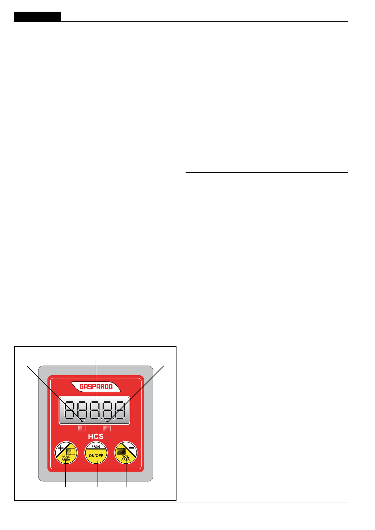
3.1 DESCRIZIONE DEL CONTAETTARI HCS
Il contaettari GASPARDO HCS è l’equipaggiamento ideale per il
conteggio e la visualizzazione dell’area lavorata (area parziale ed
area totale) e conteggio delle ore di lavoro.
Dalla versione software 2.0 in poi, il contaettari GASPARDO HCS
è dotato della funzione di Auto-calibrazione della costante “C”
(vedi pag. 8).
A) Display 5 cifre retro-illuminato per la visualizzazione di area
totale, area parziale e ore di lavoro.
B) Segmento display che indica il totalizzatore area parziale.
C) Segmento display che indica il totalizzatore area totale.
D) Tasto per selezionare/azzerare il totalizzatore area parziale;
nella fase di programmazione permette di aumentare il valore
della costante selezionata.
E) Tasto ON/OFF; tenendolo premuto a monitor acceso permette
di entrare nella fase di programmazione.
F) Tasto per selezionare/azzerare il totalizzatore area totale; nella
fase di programmazione permette di diminuire il valore della
costante selezionata.
Si consiglia d’installare il Monitor frontalmente all’operatore per
facilitarne l’uso durante il ciclo di lavoro.
Il contaettari HCS permette di visualizzare:
- Area totale lavorata: 0000.0 ÷ 9999.9 Ha con passi di 0.1 Ha;
se si superano 9999.9 Ha senza azzerare, il totalizzatore riparte
automaticamente da 0000.0.
- Area parziale lavorata: 000.00 ÷ 999.99 Ha con passi di 0.01Ha;
se si superano 999.99 Ha senza azzerare, il totalizzatore riparte
automaticamente da 000.00
- Ore di lavoro: 0000.0 ÷ 9999.9 ore con passi di 0.1 ore (6 minuti);
se si superano 9999.9 ore senza azzerare il totalizzatore riparte
automaticamente da 0000.0; le ore di lavoro vengono incremen-
tate SOLO in presenza di impulsi dal sensore di velocità.
3.2 DATI TECNICI
HCS
- Tensione di alimentazione 10÷16 Vdc
- Corrente massima assorbita 250 mA
- Fusibile Interno, Auto-ripristinante
Caratteristiche di funzionamento
- Grado di protezione IP 65
- Resistenza vibrazioni meccaniche 2 G
Condizioni di funzionamento
- Temperatura ambiente -20°C / +70°C
- Condizioni atmosferiche Umidità relativa 90%
Trasporto e immagazzinaggio
- Temperatura -25°C / +85°C
Sensore magnetico di velocità
- Tensione di alimentazione 220 V (max)
- Frequenza max. di lavoro 230 Hz (max)
- Temperatura di lavoro -20/+80 °C
- Distanza max. di intervento 15-20 mm
- Grado di protezione IP67
Cablaggi
- Connettore sensore AMP Super seal 2 vie
- Connettore alimentazione 3 poli
- Temperatura di funzionamento -20°C / +80°C
I dati tecnici ed i modelli indicati si intendono non impegnativi.
Ciriserviamoildirittodimodicarlisenzaobbligodipreavviso.
ACB
E FD
g. 4
USO E MANUTENZIONE
7
ITALIANO
cod. G19502721
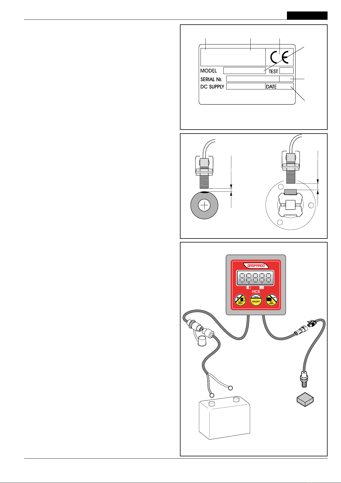
3.3 IDENTIFICAZIONE
Ogni singola attrezzatura, è dotata di una targhetta di identica-
zione (Fig. 2), i cui dati riportano:
1) Marchio CE;
2) Marchio del Costruttore;
3) Nome, ragione sociale ed indirizzo del Costruttore;
4) Tipo Accessorio;
5) Numero di Matricola;
6) Anno di costruzione.
Tali dati vanno sempre citati per ogni necessità di assistenza o
ricambi.
3.4 MONTAGGIO SENSORE VELOCITÀ
Seguire le istruzioni di montaggio riportate da pag. 77.
POSIZIONAMENTO SENSORE VELOCITÀ
Inserire il sensore sul supporto regolandolo ad una distanza di
circa 3÷5 - 10÷15 mm dal supporto di lettura (Fig. 3).
IMPORTANTE:
Fissaretuttiicavielettricilungolepartissedell’attrezzatura
con le apposite fascette in dotazione.
3.5 COLLEGAMENTO
Il monitor deve essere ssato sempre all’interno della cabina della
trattrice in posizione comoda per l’utilizzatore utilizzando il supporto
adesivo in dotazione. Esso dev’essere collegato, per mezzo
della connessione (G, Fig. 4), alla batteria 12 Volt.
Il monitor è dotato di un accumulatore che permette di mantenere
in memoria i dati inseriti.
Il monitor è protetto contro i cortocircuiti e contro l’inversione
della polarità, per mezzo di un fusibile termico autoripristinante
(polyswitch): una volta intervenuta la protezione, il monitor si spe-
gne. Prima di riaccenderlo è consigliabile scollegarlo dalla batteria
del trattore per qualche minuto.
2 3 1
4
5
6
g. 2
12 V
g. 3
g. 4
G
10÷15 mm
3÷5 mm
USO E MANUTENZIONE
8
ITALIANO
cod. G19502721
3.6 PROGRAMMAZIONE
3.6.1 COSTANTE “C”
La costante C (Fig. 5) corrisponde alla distanza percorsa (in metri
lineari) tra il rilevamento, del sensore di velocità, di un impulso ed
il successivo.
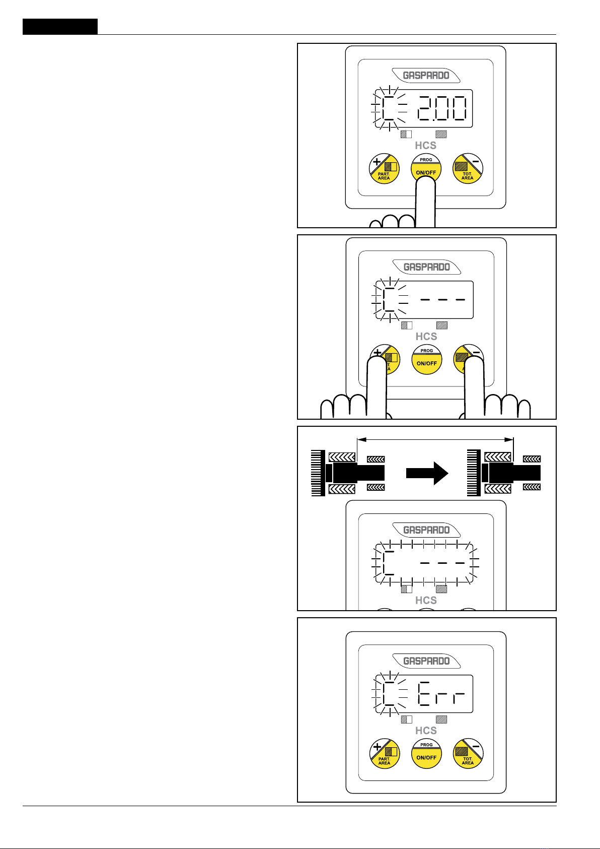
PROGRAMMAZIONE MANUALE COSTANTE “C”
A monitor acceso, tenere premuto per 5 secondi il tasto ON/OFF,
sul display comparirà la prima costante C(lampeggiante), succes-
sivamente rilasciare il tasto ON/OFF.
Con i tasti “+” e “-”, inserire il coefcente, relativo al modello di
macchina e tipo di ruota in uso, indicato nel rispettivo schema di
montaggio (da pag. 45).
(Premere e mantenere per velocizzare la progressione della nu-
merazione).
Campo impostabile: 0,01÷10,00
Step: 0,01
Default: 2,00
Premere il tasto ON/OFF per confermare e passare alla program-
mazione della costante successiva.
AUTO-CALIBRAZIONE COSTANTE “C”
(solo con versione software 2.0, vedi pag.6)
A monitor acceso, tenere premuto per 5 secondi il tasto ON/OFF,
sul display comparirà la prima costante «C» (lampeggiante), suc-
cessivamente rilasciare il tasto ON/OFF.
Con la costante «C» visualizzata (lampeggiante, Fig. 5), è possibile
avviare la procedura di auto-calibrazione.
Prima di avviare la procedura, posizionarsi all’inizio di un tratto
rettilineo di 100metri e premere CONTEMPORANEAMENTE i
tasti “+” e “-”.
Sul display compariranno 3 trattini orizzontali accesi ssi (Fig. 6).
Iniziare a percorrere i 100 metri, i trattini inizieranno a lampeggiare
assieme alla lettera «C» (Fig. 7).
Fermarsi alla ne dei 100metri e premere il tasto centrale «E»: il mo-
nitor visualizzerà sul display il valore della costante «C» calcolata.
La costante «C» deve avere un valore compreso tra 0.01metri e
10.00metri altrimenti il monitor visualizza “C Err” per un secondo
dopodichè ripropone l’ ultimo valore valido programmato in pre-
cedenza (Fig. 8).
Eventualmente ripetere la procedura di auto-calibrazione premendo
contemporaneamente i tasti “+” e “-”oppure premendoli sepa-
ratamente è possibile modicare manualmente il valore di «C».
g. 5
g. 6
100 m
g. 7
g. 8

USO E MANUTENZIONE
9
ITALIANO
cod. G19502721
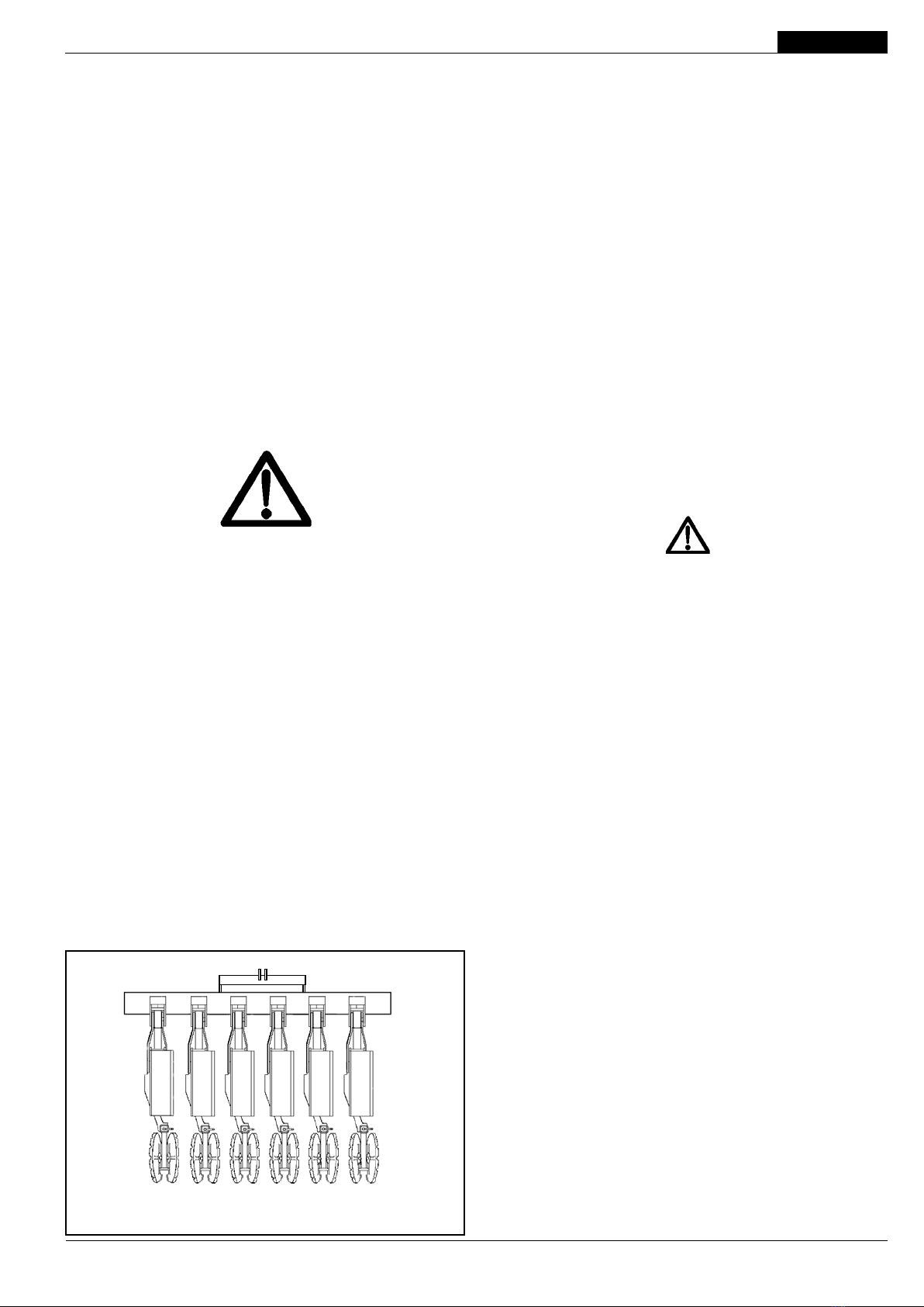
3.6.2 COSTANTE “L”
Il secondo valore richiesto per la programmazione è la larghezza
di lavoro in metri (Fig. 9), ricavabile dalla formula che segue:
Larghezza lavoro (metri) = Interla (metri) x nr.le
Inserire il valore con i tasti “+” e “-” e confermare con il tasto
“ON/OFF”.
Campo impostabile: 0,10÷40,00
Step: 0,01
Default: 6,00
Alla conferma di quest’ultimo valore il display visualizzerà auto-
maticamente tutti i valori impostati ed in ne si posizionerà in 0.00
pronto per il conteggio.
g. 9

USO E MANUTENZIONE
10
ITALIANO
cod. G19502721
3.7 FUNZIONAMENTO
All’accensione, il monitor esegue un test della durata di circa 2
secondi. Al termine del test viene visualizzata per circa 1 secondo
la versione del software (es: “U 2.0”).
Successivamente vengono visualizzate per circa 3 secondi le ore
di lavoro; durante i tre secondi è possibile azzerare le ore tenendo
premuto uno dei tasti “+” o “-”.
Successivamente sul display verrà visualizzata l’area parziale
lavorata (accensione del relativo segmento B).
Durante il lavoro, controllare periodicamente il puntino nel display
(Fig. 10): il lampeggiare corrisponde ad un corretto rilevamento
degli impulsi.
ATTENZIONE
-Seil puntinonon devesselampeggiare, vericareche il
sensore sia stato correttamente montato.
- Controllare che eventuali residui non permettano la regolare
lettura degli impulsi.
3.7.1 LETTURA DELLE SUPERFICI
Il contaettari HCS permette una semplice lettura delle superci
parziale e totale lavorate, operando come segue:
- SuperciePARZIALE: questo è sempre visibile in posizione di
lavoro, con due cifre decimali (es: 48.32, Fig. 11).
- SupercieTOTALE: premere per un secondo il tasto “-”, il con-
taettari visualizzerà con una cifra decimale la supercie totale
lavorata (es: 62.8, Fig. 12).
3.7.2 AZZERAMENTO DELLE SUPERFICI
- SuperciePARZIALE: Premere e mantenere per almeno 3
secondi il tasto “+” no all’azzeramento 0.00, con questa ope-
razione sarà azzerato il valore della supercie parziale.
- SupercieTOTALE: Premere il tasto “-” per visualizzare l’area
totale, successivamente Premere e mantenere per almeno 3
secondi il tasto “-” no all’azzeramento 0.0, con questa opera-
zione saranno azzerati i valori della supercie parziale e totale.
g. 10
g. 12
g. 11
USO E MANUTENZIONE
11
ITALIANO
cod. G19502721
4.0 MANUTENZIONE
Sono di seguito elencate le varie operazioni di manutenzione da
eseguirsi con periodicità:
- Vericare il corretto ssaggio del sensore.
- Vericare che nessun corpo estraneo possa interporsi fra il
magnete ed il sensore.
- Custodire l’attrezzatura in un ambiente asciutto e coperto. Se
ciò non fosse possibile, si RACCOMANDA di preteggerla con
un telo ponendo particolare attenzione alle parti elettriche.
5.0 PARTI DI RICAMBIO
Le ordinazioni delle parti di ricambio vanno fatte presso i nostri
concessionari di zona e devono essere sempre corredate dalle
seguenti indicazioni:
-Tipo, modello e numero di matricola dell’attrezzatura. Tali
dati sono stampigliati nell’apposita targhetta di cui è dotata ogni
attrezzatura.
- Numero di codice della parte richiesta rilevabile dal catalogo
ricambi.
- Descrizione del particolare e quantità richiesta.
- Numero della tavola.
- Mezzo di trasporto. Nel caso questa voce non sia specicata,
la Ditta Costruttrice, pur dedicando a questo servizio una parti-
colare cura, non risponde di eventuali ritardi di spedizione dovuti
a cause di forza maggiore.
Le spese di trasporto si intendono sempre a carico del destinatario.
La merce viaggia a rischio e pericolo del committente anche se
venduta franco destino.
NOTA: Il termine (Dx) Destro o (Sx)Sinistro della macchina o di
parti di essa, è inteso guardando la macchina dalla parte posteriore
(Fig. 13). Le eccezioni saranno indicate.
6.0 MONTAGGIO
Fare molta attenzione ad effettuare l’intera operazione se-
guendo le istruzioni.
PAGINA 77
g. 13
Sinistra
Left
Links
Gauche
Izquierda
Destra
Right
Rechts
Droit
Derecha
ATTENZIONE
Custodire l’attrezzatura in un ambiente
asciutto e coperto. Se ciò non fosse possibile,
si RACCOMANDA di preteggerla con un telo
ponendo particolare attenzione alle parti
elettriche.

12 cod. G19502721

ENGLISH
13
cod. G19502721
1.0 INTRODUCTION
This manual gives all the specic information that you need for a
proper use of the equipment. After buying the instrument, read the
manual carefully and refer to it any time you have doubts on how
to use the equipment or when you have to carry out maintenance
operations. Keep the manual on the machine. If this is not possible,
keep it ready to hand.
Regular operation depends on the correct use and adequate
maintenance of the equipment. It is advisable therefore to observe
scrupulously what is described in order to prevent any inconve-
niences that could prejudicate proper operation and duration. The
equipment must be used, maintained and repaired by trained per-
sonnel that have been instructed on the dangers arising from its
incorrect use. All the safety regulations and provisions for technical
safety, occupational medicine and the Highway Code must also be
observed. The manufacture is not liable for any damage to property
or injury to persons due to modications made to the equipment by
the user. It is just as important to keep to what is described in this
booklet since the Manufacturer declines all responsibility due
to negligence and non-observance of these rules. At any rate
the Manufacturer is available to assure immediate and accurate
technical assistance and all that may be necessary for the improved
operation and better performance of the equipment.
1.1 GUARANTEE
The guarantee is valid for a year, against all defects of material,
from the date of delivery of the equipment.
On delivery, check that the equipment has not been damaged du-
ring transport and that the accessories are integral and complete.
POSSIBLE CLAIMS MUST BE PRESENTED IN WRITING WITHIN
EIGHT DAYS OF RECEIPT.
The purchaser will enforce his rights on the guarantee only when
he has respected the conditions concerning the benet of the
guarantee, set out in the supply contract.
1.1.1 EXPIRY OF GUARANTEE
Besides what has already been set out in the supply contract,
the guarantee expires:
- If the limits set out in the technical data table are overshot.
- If the instructions set out in this booklet have not been carefully
followed.
- If the equipment is used badly, defective maintenance or other
errors by the client.
- If modications have been carried out without written authorization
of the manufacturer and if non original spare parts have been
used.
2.0 SAFETY REGULATIONS AND ACCIDENT PRE-
VENTION
Carefully read all the instructions before using the equipment;
if in doubt, contact the technicians of the Manufacturer’s de-
aler. The manufacturer declines all responsibility for the non-
observance of the safety and accident prevention regulations
described below.
General norms
- The equipment is exclusively designed for a specic agricultural
use. Any other use is considered improper.
- In the event of improper use, the Manufacturer declines all re-
sponsibility for any damage to persons and property. The risks
created by improper use are the sole responsibility of the user
of the equipment.
- Specic use also includes observance of the operating and
maintenance conditions laid down in this manual.
- The relevant generally accepted accident-prevention regulations
must be observed, in addition to the latest standards relative to
safety measures, occupational medicine and the highway code.
- The Manufacturer declines all responsibility for unauthorized
modications made to the equipment.
Maintenance in safety
During work and maintenance operations, use suitable per-
sonal protection gear:
Overalls Gloves Shoes Goggles Ear
defenders
- Before performing work on the electrical system, disconnect the
battery.
- If welding operations need to be performed either on the tractor or
on the mounted equipment, disconnect the battery power supply.
- Do not carry out maintenance or cleaning work before the engine
has been switched off, the hand brake has been put on and the
tractor has been blocked with a suitably sized stone under each
wheel.
- All maintenance work, adjustments and preparation for opera-
tion, must be carried out with the power take-off of the tractor
disconnected, the seeder on the ground on its supporting feet,
the tractor not running, the wheels blocked and the key turned
off.
- The spare parts must correspond to the manufacturer’s speci-
cations. Use only original spares.
USE AND MAINTENANCE
ENGLISH
14 cod. G19502721
3.2 TECHNICAL DATA
HCS
- Power supply voltage 10÷16 Vdc
- Max. energy consumption 250 mA
- Fuse Internal, Self-restoring
Functioning characteristics
- Protection degree IP 65
- Mechanic vibrations resistance 2 G
Functioning conditions
- Room temperature -20°C / +70°C
- Weather conditions Relative humidity 90%
Transport and storage
- Temperature -25°C / +85°C
Speed sensor
- Power supply voltage 220 V (max)
- Max. working frequency 230 Hz (max)
- Working temperature -20/+80 °C
- Max. operation distance 15-20 mm
- Protection degree IP67
Cables
- Sensor connector AMP Super seal 2-way
- Power connector 3 poles
- Functioning temperature -20°C / +80°C
The technical data and the models provided must be consi-
dered as non binding. We reserve the right to change them
without notice.
3.0 INSTRUCTIONS FOR USE
3.1 DESCRIPTION OF HECTARE COUNTER HCS
GASPARDO hectare counters HCS are the ideal equipment for
counting and viewing the tilled area (partial and total) as well as
for counting the hours of operation.
From software version 2.0 on, the GASPARDO HCS hectare
counter is equipped with the Self-calibration of constant “C” fun-
ction (see page 16).
A) 5-digit backlit display showing the total area, partial area and
the hours of operation.
B) Display section showing the partial area counter.
C) Display section showing the total area counter.
D) Key for partial area counter selection/resetting: during program-
ming this key is pressed to increase the value of the selected
constant.
E) ON/OFF button: hold this button pressed with the monitor on
to access the programming phase.
F) Key for total area counter selection/resetting; during program-
ming this key is pressed to reduce the value of the selected
constant.
We recommend installation of the monitor opposite the operator
so that it is easier to use during the working cycle.
Hectare counters HCS enable viewing of the following:
- total area tilled: 0000.0 ÷ 9999.9 Ha with 0.1 Ha pitches; if 9999.9
Ha is exceeded without resetting, the counter automatically starts
from 000.00 again.
- partial area tilled: 000.00 ÷ 999.99 Ha with 0.01Ha pitches; if
999.99 Ha is exceeded without resetting, the counter automati-
cally starts from 000.00 again.
- hours of operation: 0000.0 ÷ 9999.9 hours with 0.1 hour pitches
(6 minutes); if 9999.9 hours are exceeded without resetting, the
counter automatically starts from 0000.0 again. The hours of
operation are increased ONLY if pulses are received from the
speed sensor.
ACB
E FD
g. 4

USE AND MAINTENANCE ENGLISH
15
cod. G19502721
3.3 IDENTIFICATION
Cada equipo está provisto de una tarjeta de identicación (Fig. 2),
en la que se encuentran:
1) Marchio CE;
2) Marca del fabricante;
3) Nombre, razón social y dirección del Fabricante;
4) Tipo de Accesorio;
5) Número de matrícula;
6) Año de fabricación.
Estos datos tendrán que mencionarse para cualquier necesidad
de asistencia o repuestos.
3.4 FIXING THE SPEED SENSOR
Follow the installation instructions provided on page 77.
SPEED SENSOR POSITIONING
Insert the sensor into the support and adjust it to a distance of
about 3÷5 - 10÷15 mm from the reading arm (Fig. 3).
IMPORTANT
tie all the electric cables to the non-moving parts of the
equipment with the cable ties supplied.
3.5 CONNECTION
The monitor must always be xed inside the tractor cab, by means
of the adhesive support provided, in a comfortable position for the
operator. It must be connected to the 12 V battery (see G, Fig.
4). The monitor is equipped with a battery which maintains the
inputted data in the memory.
The monitor is protected against short circuit and polarity inversion
thanks to a self-resetting thermal fuse (polyswitch). When this pro-
tection triggers, the monitor goes off. Before switching the monitor
on again, we recommend disconnecting it from the battery of the
tractor for a few minutes.
2 3 1
4
5
6
g. 2
12 V
g. 3
g. 4
G
10÷15 mm
3÷5 mm

USE AND MAINTENANCE
ENGLISH
16 cod. G19502721
3.6 PROGRAMMING
3.6.1 “C” COSTANT
Constant C (Fig. 5) indicates the distance travelled (in linear metres)
between two consecutive pulses measured by the speed sensor.
MANUAL PROGRAMMING OF CONSTANT “C”
With the monitor on hold the ON/OFF button pressed for 5 secon-
ds: the rst constant «C» (ashing) appears on the display. Now,
release the ON/OFF button.
Using the “+” and “-” keys, enter the coefcient for the machine
model and wheel type in use, as shown in the relevant assembly
diagram (on page 45) .
(To press and to maintain in order to accelerate the progression
of the numeration).
Settingeld: 0,01÷10,00
Step: 0,01
Default: 2,00
Press the ON/OFF button to conrm and move on to programming
of the next constant.
SELF-CALIBRATION OF CONSTANT “C”
(only with software version 2.0 See page 14)
With the monitor on hold the ON/OFF button pressed for 5 secon-
ds: the rst constant «C» (ashing) appears on the display. Now,
release the ON/OFF button.
with constant C displayed (ashing, Fig. 5), the self-calibration
procedure can be started.
Before starting the procedure, position yourself at the start of a
straight 100 metre section and SIMULTANEOUSLY press buttons
“+” and “-”.
3 horizontal dashes will appear on the display lit up with a steady
light (Fig. 6).
Start to travel along the 100 metres and the dashes will start to
ash together with the letter «C» (Fig. 7).
Stop at the end of the 100 metres and press the centre button «E»:
the monitor will display the value of the calculated constant «C».
Constant «C» must have a value between 0.01 metres and 10.00
metres, otherwise the monitor will display “C Err” for one second,
after which it will show the last previously programmed valid value
(Fig. 8).
If necessary, repeat the self-calibration procedure by pressing
buttons “+” and “-” simultaneously, or else the value of «C» can
be modied manually by pressing them separately «C».
g. 5
g. 6
100 m
g. 7
g. 8

USE AND MAINTENANCE ENGLISH
17
cod. G19502721
3.6.2 “L” COSTANT
The working width (Fig. 9) is the other value requested and can be
found with the following formula:
Working width (meters) = Row distance (meters) x n° row
Using the “+” and “-” keys, conrm by pressing the “ON/OFF” key.
Settingeld: 0,10÷40,00
Step: 0,01
Default: 6,00
Upon conrming this value the display will automatically show all
the entered values and nally will return to 0.00, ready for the count.
g. 9

USE AND MAINTENANCE
ENGLISH
18 cod. G19502721
3.7 FUNCTIONING MODE
When the monitor is switched on, a test of approx. 2 seconds is
run. At the end of the test, the version of the software (e.g.: “U 2.0”)
is displayed for about 1 second.
Successively, the hours of operation are displayed for approx. 3
seconds and during this period the hours can be reset by pressing
either the “+” or “-” key.
After this operation the partial tilled area is shown on the display
(section B switches on).
During operation periodically check the dot on the display (Fig.
10): if it ashes pulses are sensed correctly.
WARNING
-Ifthedotdoesnotash,checkthatthesensoriscorrectly
mounted.
- Check that residue is not impeding normal impulse reading.
3.7.1 SURFACE READINGS
The HCS hectare-counter permits simple reading of partially or
totally covered surfaces, operating in the following way:
- PARTIAL surface: this value is always shown with two decimals
in operation mode (e.g. 48.32, Fig. 11).
- TOTAL surface: press the “-” key for one second; the hectare
counter shows the total tilled area with one decimal (e.g. 62.8,
Fig. 12).
3.7.2 RESETTING THE SURFACES
- PARTIAL surface: press the “+” key and hold it pressed for at
least 3 seconds until it is reset to 0.00. This operation enables
resetting of the partial surface value.
- TOTAL surface: press the “-” key to view the total area. Then,
press the “-” key and hold it pressed for at least 3 seconds until
it is reset to 0.0. This operation enables resetting of both the
partial and total surface values.
g. 10
g. 12
g. 11

USE AND MAINTENANCE ENGLISH
19
cod. G19502721
4.0 MAINTENANCE
Maintenance operations to be carried periodically are as follows:
- Check that the sensor is properly attached (5-10 mm from the
magnet).
- Make sure that no foreign matter comes between the magnet
and the sensor.
- Store the device in a dry and covered place. If this is not possi-
ble we strongly advise covering it with a cloth, paying especial
attention to the electrical components.
5.0 SPARE PARTS
Orders must be transmitted through our area dealers and should
always include the following indications:
- Type, model and serial number of the machine. These data
are punched on the data plate with which every implement is
equipped.
- Code number of the required spare part. This will be found in
the spare parts catalogue.
- Description of the part and required quantity.
- Table number.
- Means of dispatch. If this item is not indicated, the Manufactu-
rer, while dedicating particular care to this service, shall not be
held responsible for delays in delivery caused by cases of force
majeure.
Transport expenses shall always be at the consignee’s charge.
The goods travel at the purchaser’s risk and peril even when sold
ex destination.
NOTE: The symbols (Dx) right and (Sx) left, concerning the ma-
chine or single parts of it, are referred, as in the gure, to a rear
view of them (Fig. 13). Exceptions will be indicated.
6.0 ASSEMBLY
Be sure to follow the instructions carefully throughout the
operation.
PAGE 77
g. 13
Sinistra
Left
Links
Gauche
Izquierda
Destra
Right
Rechts
Droit
Derecha
ATTENTION
Store the equipment in a dry and indoor
place. Should this not be possible, it is
RECOMMENDED to cover it with a rubber cloth
paying attention to the electric devices

20 cod. G19502721
Table of contents
Other Gaspardo Farm Equipment manuals

Gaspardo
Gaspardo Vitigreen 1300 User guide

Gaspardo
Gaspardo SP User guide

Gaspardo
Gaspardo VITTORIA 250 User guide

Gaspardo
Gaspardo PA1 User guide

Gaspardo
Gaspardo SD Series User guide

Gaspardo
Gaspardo M User guide

Gaspardo
Gaspardo ORIETTA Series User guide

Gaspardo
Gaspardo COMBINATA 250 Guide

Gaspardo
Gaspardo F Plus Guide

Gaspardo
Gaspardo PI 400 User guide

Gaspardo
Gaspardo XPI 800 Guide

Gaspardo
Gaspardo DP User guide

Gaspardo
Gaspardo PA1 User guide

Gaspardo
Gaspardo G19502451 User guide

Gaspardo
Gaspardo Primavera User guide

Gaspardo
Gaspardo DP PRONTA 300 User guide

Gaspardo
Gaspardo ORIETTA User guide

Gaspardo
Gaspardo NINA User guide

Gaspardo
Gaspardo PENTA PE User guide

Gaspardo
Gaspardo CENTAURO User guide


