Hardy Process Solutions HI 6600-EIP User manual
HI 6600 Series Modular Sensor System User Guide
Page | 1
HI 6600 Series Modular Sensor System
User’s Guide
Hardy Process Solutions Document Number: 0596-0333-01 REV D

HI 6600 Series Modular Sensor System User Guide
Local Field Service
Hardy Process Solutions provides local field service for all scales and weighing equipment. Hardy’s factory
trained technicians can perform service on all Hardy equipment as well as most other manufacturers’
systems. Enabled by the Hardy Process Toolbox, our technicians spend less time onsite, saving you money
and reducing your downtime.
Services Include:
• Installation & Commissioning
• Preventative Maintenance & Calibration
• Onsite Emergency Service
• Service Agreements with Defined Turnaround Times
• Product, Service, and PLC Integration Training
• Pre-Installation Site Audit
• Scale Installed-Base Evaluation
• PLC Integration Support
• Engineering Design Support & Specification Development
• Quality Documentation Creation
Contact Us
To request any of the services mentioned, or to discuss your needs with a trained Hardy Service Agent,
please call 800-821-5831 Option 4 (6:30 AM to 5:30 PM PST). For emergency downtime service after
hours, leave a message in our emergency mailbox and your call will be returned promptly

HI 6600 Series Modular Sensor System User Guide
Page | 3
Contents
• • • • • •
Chapter 1.........................................................................................................................................8
HI 6600 Series Overview................................................................................................................8
Introduction to the HI 6600 Modular Sensor System..............................................................8
Typical Applications
..........................................................................................................10
HI 6600 Series Model Numbers
..........................................................................................10
Chapter2
.........................................................................................................................................11
SpecificationsandFeatures
................................................................................................................11
Basic Specifications
.................................................................................................................11
HI 6610 Weight Processing Module (WPM) .................................................................11
Hardy Gateway Module (HI 6600).......................................................................................12
Network Connectivity
......................................................................................................12
OptionalHI6110FrontPanelDisplay
..................................................................................13
Environmental Requirements
..............................................................................................13
Approvals .......................................................................................................................13
Network Certifications
.......................................................................................................13
Features and Capabilities
...........................................................................................................13
Hardy Process Toolbox
.......................................................................................................13
C2® Calibration
................................................................................................................13
INTEGRATED TECHNICIAN®
........................................................................................14
WAVERSAVER®...........................................................................................................14
Power Requirements for Configuring Your Modular Sensor System over Distance............14
Chapter3
.........................................................................................................................................18
HI6600HardwareInstallation
............................................................................................................18
Safety
.....................................................................................................................................18
General Precautions
...........................................................................................................18
Unpacking.............................................................................................................................18
Tool List.........................................................................................................................19
Installing the HI 6610 Modules ............................................................................................19
Overview of the HI 6600 Hardware......................................................................................20
Installation......................................................................................................................21
Cabling the Units Together
..................................................................................................22
DC Power Input ....................................................................................................................23
Connecting Sensors........................................................................................................24
Installing the Optional Display
..................................................................................................25
BlindUnit(Nodisplay)
......................................................................................................25
Optional Remote Display Mount
.........................................................................................25
Mounting theOptional FrontPanel Display....................................................................26
Making Longer Display Interface Cables
.............................................................................28
Chapter 4.......................................................................................................................................29
InstrumentConfiguration
..................................................................................................................29
Using the Webserver.............................................................................................................30

HI 6600 Series Modular Sensor System User Guide
Page | 4
Using the HI 6110 Front Panel Display
....................................................................................31
Mode Button
.....................................................................................................................32
Channel Identification
...............................................................................................................33
System Discovery
..............................................................................................................33
Instrument ID .................................................................................................................34
Channel Identification ....................................................................................................34
Deleting Channels
.............................................................................................................35
Replace Channel.............................................................................................................35
Saving and Restoring Configuration Data Using the USB port.........................................36
Suggested Minimum Steps When Setting Up the Instrument For the First Time...........36
Setup Parameter Menus
............................................................................................................37
Capacity Parameter
..........................................................................................................37
Decimal Point Parameter................................................................................................37
Graduation Size Parameter.............................................................................................38
Instrument ID .................................................................................................................38
Motion Tolerance Parameter ..........................................................................................38
Operator ID Parameter
.....................................................................................................38
Unit (of Measure) Parameter..........................................................................................38
Filter Parameter Menu
........................................................................................................39
NumAverages Parameter
..................................................................................................39
WAVERSAVER® Parameter
...........................................................................................39
Calibration
..............................................................................................................................40
Pre-Calibration Procedures
.................................................................................................40
ElectricalCheckProcedures..................................................................................................41
Load Cell/Point Input/Output Measurements.................................................................41
Load Check
.......................................................................................................................42
C2 & eCAL Electronic Calibration
.............................................................................................42
C2andeCALCalibration
Commands and Parameters .......................................................42
Sensitivity Parameter
........................................................................................................42
Ref Weight Parameter
.......................................................................................................42
Cal Tolerance Parameter
...................................................................................................43
Gravitation Correction....................................................................................................43
C2 Calibration Process
.....................................................................................................45
HardCalibration....................................................................................................................46
Hard Cal Commands and Parameters.............................................................................46
Cal Lo Weight Parameter
.................................................................................................46
Cal Tolerance Parameter
...................................................................................................46
Do Cal Lo Command
.......................................................................................................46
Do Cal Hi Command
........................................................................................................46
Span Weight Parameter
....................................................................................................47
Chapter 5
........................................................................................................................................48
InstrumentOperation
........................................................................................................................48
Operations.............................................................................................................................48
Tare Parameters and Commands
................................................................................................48
Tare Amount
....................................................................................................................48
Tare Offset
.......................................................................................................................49
Tare Command
.................................................................................................................49
Zero Parameters and Commands
................................................................................................49
Zero Tolerance
.................................................................................................................49
Zero Amount
....................................................................................................................50

HI 6600 Series Modular Sensor System User Guide
Page | 5
Zero Command
................................................................................................................50
Auto Mode
........................................................................................................................50
Count Operations
.....................................................................................................................51
Determining Piece Count:
.................................................................................................51
Chapter 6.......................................................................................................................................52
NetworkCommunications
.................................................................................................................52
Maximum Number of Channels Supported for PLC Communication Formats .............53
LAN Connection ............................................................................................................53
IP address. ......................................................................................................................54
Enable DHCP
..................................................................................................................54
Mask Address Parameter................................................................................................54
Gateway Address Parameter
.............................................................................................54
DNS Server Parameter
.....................................................................................................55
Fixed IP Configuration...................................................................................................55
Direct Connect Hardware...............................................................................................55
Windows PC Configuration: Windows 2000 ................................................................56
Windows XP
....................................................................................................................56
Windows 7
.......................................................................................................................56
DirectConnectConfiguration-HI6600HGM
......................................................................57
EtherNet/IP
®
...........................................................................................................................57
EtherNet/IP Commands and Parameters
..................................................................................58
TheEtherNet/IPDiagnosticsScreen................................................................................58
Ethernet UDP Parameters
.........................................................................................................60
Hardy Port ......................................................................................................................60
Modbus TCP
...........................................................................................................................60
Modbus TCP Commands and Parameters......................................................................60
InstallingtheHardyModbus-LinkTestPackage..............................................................62
Configuring MODBUS TCP
.............................................................................................62
Profibus-DP ..........................................................................................................................67
Profibus Configuration
.......................................................................................................67
Initialization Process
........................................................................................................68
Profibus-DP.GSDFile....................................................................................................69
Pre-Initialization Procedures
.............................................................................................69
Modbus-RTU (over RS-485)
.....................................................................................................74
Modbus-RTU Commands and Parameters
............................................................................74
Slave Address Parameter
..................................................................................................74
Baud Rate Parameter.......................................................................................................74
ParityParameter..............................................................................................................75
Modbus Setup
..................................................................................................................76
Modbus Functions
............................................................................................................76
USB Memory Stick
..................................................................................................................77
Restore Command
............................................................................................................78
Chapter 7.......................................................................................................................................79
Security.........................................................................................................................................79
Optional HI 6110 Display Security Options
................................................................................79
The Display Lock
..............................................................................................................80
The Keypad Lock
..............................................................................................................83
The Configuration Lock
.....................................................................................................84
The Read Only, Security & Calibration Locks...............................................................86
Modifying the Calibration Parameters
..................................................................................88

HI 6600 Series Modular Sensor System User Guide
Page | 6
Modifying the Read Only Parameters
...................................................................................88
Chapter 8.......................................................................................................................................89
Troubleshooting............................................................................................................................89
Assembly Notes, Warnings & Cautions
.......................................................................................89
Updating Instrument Firmware
...........................................................................................90
Information Page
...............................................................................................................90
Indicator Lights Summary..............................................................................................91
Common Error Messages
..........................................................................................................92
Diagnostics............................................................................................................................92
Trouble Shooting Using Integrated Technician (IT®)
.............................................................92
Stability Test ALL
.............................................................................................................93
PASS/FAIL and Stability Test
.............................................................................................93
WAVERSAVER TEST
....................................................................................................93
Weight and Voltage ALL...............................................................................................93
RTZ(ReturntoZero)Test
....................................................................................................94
ITTest
..............................................................................................................................94
General Troubleshooting Flow Chart Index
..................................................................................96
A-ElectricalandMechanicalReview
..........................................................................................97
A1.CheckingforUnstableComponentsinaWeighingSystem
.........................................................98
B. Guidelines for Electrical, Mechanical or Configuration Issues
...................................................99
B1-GuidelinestoVerifyElectricalInstallation
...........................................................................100
B2-GuidelinestoVerifyMechanicalInstallation
........................................................................101
B3-VerifyConfiguration/FilterSettingstoImproveStability
.......................................................102
C-IntegratedTechnicianandStabilityTestOverview
..................................................................103
ENon-ReturntoZero(SystemwithITSummingCard.)
...............................................................104
F. Verify Individual Load Sensor Millivolt Output readings
.........................................................105
G- Calibration Errors During Calibration
..................................................................................106
H. Mechanical Installation
......................................................................................................107
J- Electrical Inspection
...........................................................................................................108
K-InstallationCheckPoints
....................................................................................................109
M. WeightProcessor’sOptionalFrontDisplayBlankorLocked
....................................................110
Tests and Diagnostics
..............................................................................................................111
Diagnostictestingfromthe OptionalFrontPanel
................................................................111
Parameters...........................................................................................................................112
SystemandLoadCellTests
......................................................................................................113
OverviewofTypicalLoadCellSystem
...............................................................................113
INTEGRATED TECHNICIAN
................................................................................................114
Stability Test
..................................................................................................................114
RunningtheStabilityTestfromtheWebInterface ...........................................................115
RunningtheStabilityTestfromtheOptionalFrontPanel.................................................115
WeightandVoltageTests................................................................................................116
WeightandVoltageTestfromtheWebinterface..............................................................116
RunningtheITtestfromtheOptionalFrontPanel ..........................................................116
Integrated Technician Test for the HI 6600 over Communications....................................117
Appendix A.................................................................................................................................121
Communications I/O Table.........................................................................................................121
I/OTablesforCommunicationstoPLCs
.....................................................................................121
OUTPUT Table Description
....................................................................................................122
Portion of the OUTPUT table used for the Hardy Gateway Module (HGM)...............122

HI 6600 Series Modular Sensor System User Guide
Page | 7
Portion of the OUTPUT table used for Weigh Processing Modules (WPMs) .............122
INPUT Table Description
........................................................................................................122
Portion of the INPUT table used for the Hardy Gateway Module (HGM)...................122
Portion of the INPUT table used for Weigh Processing Modules (WPMs) .................123
Hardy Command Numbers
......................................................................................................124
Appendix B.................................................................................................................................126
DefaultParameterIDsandValues
.....................................................................................................126
Default Parameters and Values Table
........................................................................................126
Appendix C.................................................................................................................................129
Drawings&Templates
....................................................................................................................129
II Diagrams.........................................................................................................................129
Image of HI 6600 Hardy Gateway Module II Diagram......................................................130
Image of HI 6610 Weight Processing Module II Diagram
...........................................................131
OptionalHI6110DisplayPanelMountingTemplate
...................................................................132
Appendix D.................................................................................................................................133
Spare Parts..................................................................................................................................133
Spare Parts Table
...................................................................................................................133
Appendix E.................................................................................................................................134
WiringJunctionBoxesor SummingCards
.........................................................................................134
C
onnecting to Hardy Junction Boxes or Summing Cards...................................................134
HI6010SummingBoxDiagram...........................................................................................135
HI6020SummingBoxDiagram...........................................................................................136

HI 6600 Series Modular Sensor System User Guide
Page | 8
Chapter 1
HI 6600 Series Overview
• • • • • •
This Manual describes installation, setup and operating procedures for the HI 6600 Series Modular Sensor
System. Be sure to read and understand all cautions, warnings, and safety procedures in this manual to ensure
safe installation and operation of the instrument.
Hardy Process Solutions sincerely appreciates your business. We encourage input about the performance and
operation of our products from our customers. Should you not understand any information in this manual or
experience any problems with this product, please contact our Technical Support Department at:
Phone:
(858) 278-2900
Toll Free:
1-800-821-5831
FAX:
(858) 278-6700
E-Mail:
hardysupport@hardysolutions.com or hardyinfo@hardysolutions.com
Website:
www.hardysolutions.com
Please visit our website for the latest revision of the HI 6600 Series User Guide and sign up for the Hardy
Newsletter to get the latest information on all Hardy products and services. For answers to technical issues
and service problems, please visit the Hardy WebTech section of our website or contact a technician by
phone during our normal operating hours (6:30 AM to 5:30 PM Pacific Time).
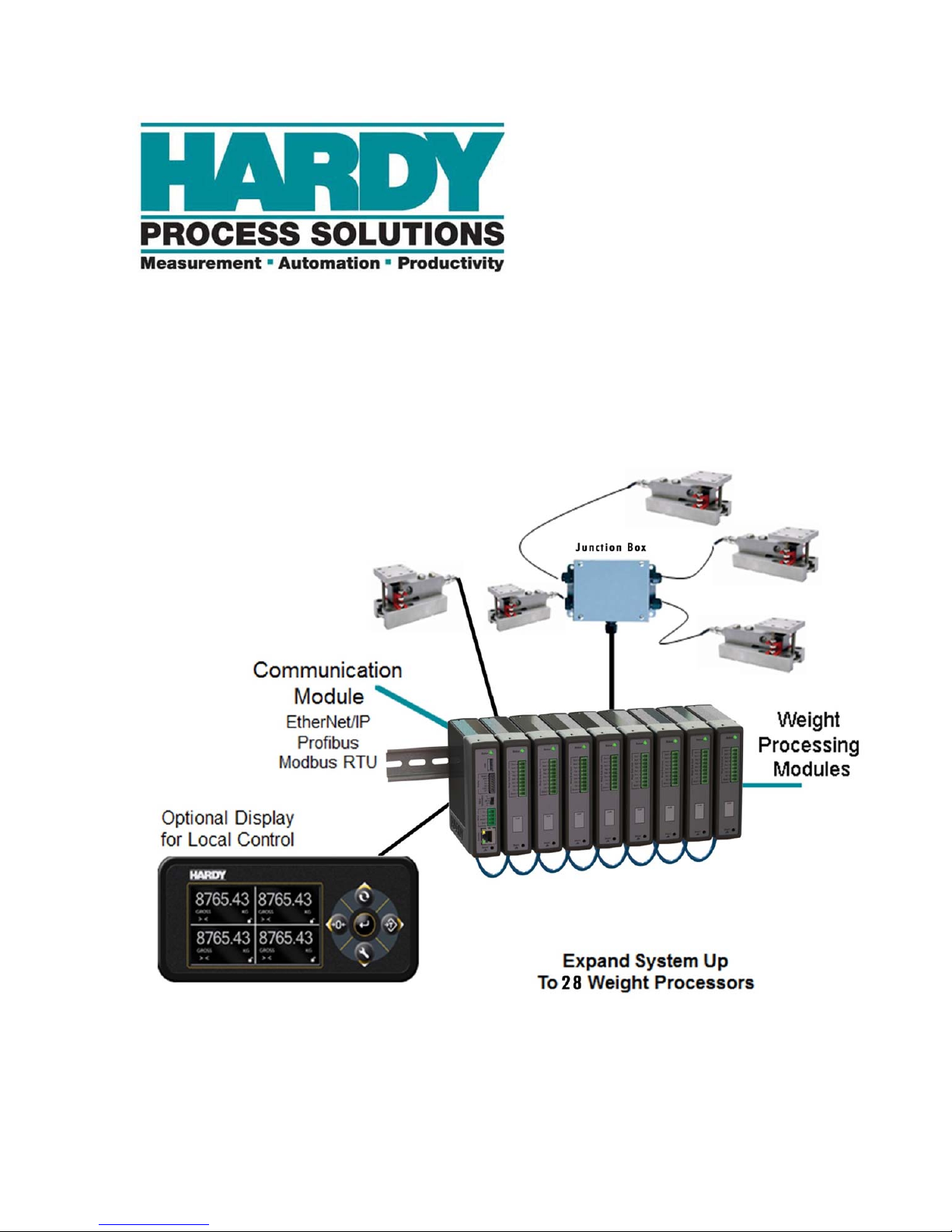
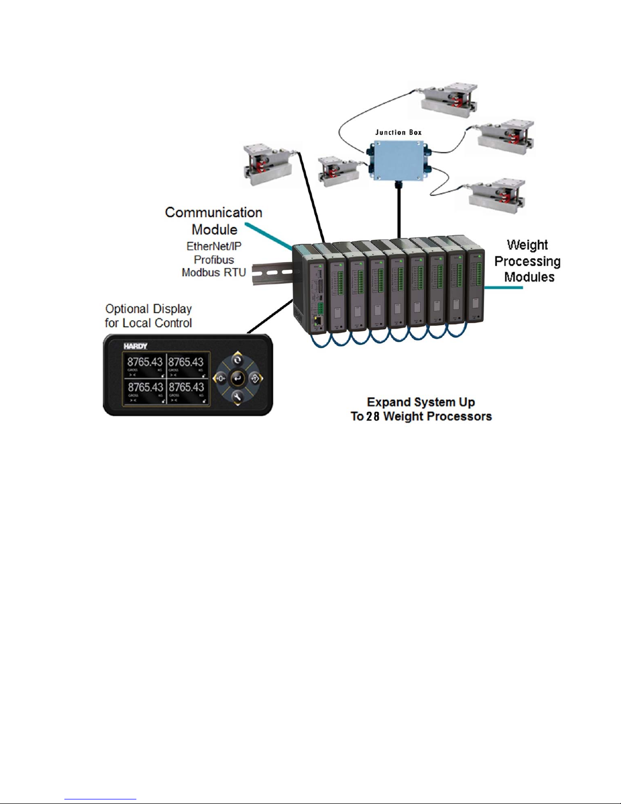
Introduction to the HI 6600 Modular Sensor System
The HI 6600 Modular Sensor System consists of at least one HI 6600 Hardy Gateway Module (HGM) and up
to 28 HI 6610 Weight Processor Modules (WPM). See specific system recommendations in Chapter 2 on
configuring a Modular Sensor System.
The system communicates with PLCs, PACs and DSCs over EtherNet/IP, Modbus-RTU, Profibus-DP and
other popular communication protocols via a single communication link.
HI 6600 Series Modular Sensor System User Guide
Page | 9
The system is used for front end signal processing of strain-gagetype sensorsand load cellsfor all types of
industrial and machine weighing applications.
Operating blind or with an optional display, the Modular
Sensor System conditions, converts and
communicatesstable processedweightreadings fromconnected
loadsensors orscales to a variety of control and monitoring systems.
The HardyNet Gateway Module (HGM or HI 6600) offers users many communication choices including
Ethernet TCP/IP, Modbus RTU, Modbus TCP and either EtherNet/IP or Profibus-DP.
The HI 6600 series can be used with or without an optional Hardy HI 6110 display. The display is a bright
4.3” high-contrast LCD capable of high-resolution graphics and help text discrete messaging. The HI 6110
display can be panel mounted near the Gateway Module or remotely up to 100 feet away to provide a user
interface for operating, calibrating or setting-up the system.
The modular array, small enclosures and low power consumption enable high density cabinet design for
systems that require up to 28 channels of processed weight.

HI 6600 Series Modular Sensor System User Guide
Page | 10
Typical Applications
Ideally suited for applications that require multiple channels of weight, the HI 6600 series serves a variety of
industrial weighing needs found in batching, blending, filling, dispensing, inventory management, level by
weight and check by weight verification.
HI 6600 Series Model Numbers
Model Number
Description
HI 6600-EIP Hardy Gateway Module-EtherNet/IP
HI 6600-PB HardyGatewayModule-Profibus-DP
HI 6610-WP Weight Processing Module, no display
HI 6110 Optional Display Panel

HI 6600 Series Modular Sensor System User Guide
Page | 11
Chapter 2
Specificationsand Features
• • • • • •
Chapter 2 provides specifications for HI 6600 series instruments. The specifications listed are designed to
assist in the installation, operation and troubleshooting of your instrument. All service personnel should be
familiar with this section before installing or repairing the instrument.
Basic Specifications
HI 6610 Weight Processing Module (WPM)
Number of Channels
Each Weight Processing Module is a single channel of weight. HI 6600 Modular Sensor System can support
up to 28 channels. The actual number of channels that can be transmitted by a single I/O table request depends
on the PLC interface format.
EtherNet/IP: Upto28Channelsperrequest
Profibus-DP Up to 10 Channels per request
Modbus-TCP: Up to 14 Channels per request
Modbus-RTU: Up to 14 Channels per request
Note: See section below on Power Requirements for Configuring your Modular Sensor System Over Distance for
specific recommendations on number of channels and maximum system distances.
UpdateRateperWeightProcessingModule(WPM)
110 times per second per channel (processed weight, display, communications)
Weight ProcessingModule(WPM) Resolution
Displayed - 1:10,000
Internal - 1: 8,388,608
WAVERSAVER®
User Selectable
OFF, 7.50 Hz, 3.50 Hz, 1.00 Hz (default), 0.50 Hz, 0.25 Hz
Averages
1to250
User-selectableinSingleIncrements

HI 6600 Series Modular Sensor System User Guide
Page | 12
LoadSensorInputperWPM
Up to four 350-ohm full Wheatstone bridge, strain gauge load sensor/cells (5 volt excitation) can be
connected to the weigh scale input on each WPM.
Note: Connecting 2 or more load cells requires a summing card or Junction Box.
Non-linearity
0.0015% of full scale
Common Mode Rejection
110 dB at or below 60 Hz
Common Mode Voltage Range
2.5 VDC maximum (with respect to earth ground)
Load Cell Excitation
5VDC+/-1.15VDCmaximum
Isolation from digital section 1000 VDC minimum
C2 Calibration Input
Isolationfromdigitalsection1000VDCminimum
Load Sensor Cable Lengths per Weight Processing Module
250feetmaximumofC2authorizedcable(Maximumof4loadsensors)witha
SummingCard
orITJunctionbox
DCInputVoltageWeightProcessingModule(with4x350ohmloadcells)
1.72Watts,12-27VDC, 71-118 mA
Maximum System Span Distance
500 feet (150 meters) span from the first Weight Processor Module to the Hardy Gateway
Module
Note: See section below on Power Requirements for Configuring your Modular Sensor System Over Distance for
specific recommendations on number of channels and maximum system distances.
Hardy Gateway Module (HI 6600)
Network Connectivity
Ethernet TCP/IP
Ethernet UDP
Modbus-RTU over RS485
Modbus TCP
EtherNet/IP (EIP models) or Profibus-DP (PB models)
USB Port: For Parameter Saving and Backup to PC
Display Port: For optional Front Panel Display
Scoreboard: Uses RS485 port to stream weight readings to a large display or data logger

HI 6600 Series Modular Sensor System User Guide
Page | 13
DCInputVoltage HardyGatewayModule(HGM)
3.90 Watts, 12-24 VDC, 162-290 mA
OptionalHI6110FrontPanelDisplay
Monochrome480x272LCDdisplaywithbacklight
Five tactile keys for menu item selection
Displays in either white on black or black on white
IP66 rated when mounted on a smooth, rigid surface (minimum 16-gage) using the supplied gasket
2 watts maximum
Environmental Requirements
Operating Temperature Range
-10ºC to 60º C (14º to 140º F)
Temperature Coefficient
Lessthan0.005%offullscaleperdegreeCforCal-LOandCal-HI referencepoints
Storage Temperature Range
-40 to 85º C (-40º to 185º F)
Humidity Range
0-90% (non-condensing)
Environmental
Intended for Building-in, indoor use only at ambient temperatures between 10ºC to 60º C (14º to 140º
F) with a pollution degree of 2.
Approvals
UL, CUL and CE
Network Certifications
EtherNet/IP ODVA Conformance Tested, Level 3
Profibus-DP by Profibus.org
Features and Capabilities
Hardy Process Toolbox
The Hardy Process Toolbox is a set of productivity tools that support process weighing functions. Each tool in
the Hardy Process Toolbox saves time, increases accuracy, improves efficiency or reduces risk in process
weighing applications. The HI 6600 includes the Toolbox functions discussed below.
C2
®
Calibration
Traditional calibration uses certified test weights. C2® Electronic Calibration allows a scale to be calibrated
without the need for test weights. A C2 weighing system consists of up to four load cell sensors per WPM, a
junction box, interconnect cable, and an instrument with C2 capabilities (e.g., the HI 6600 series instrument).
Each Hardy Process Solutions C2-certified load sensor outputs digital information used for calculating the

HI 6600 Series Modular Sensor System User Guide
Page | 14
calibration. When the HI 6600 series instrument reads the signals from the load sensors, it calibrates the scale
based on the load sensor’s output plus a user-supplied reference point value (from 0 to any known weight on
the scale).
INTEGRATED TECHNICIAN
®
In conjunction with an IT junction box, the HI 6600 series features INTEGRATED TECHNICIAN® (IT), a
system diagnostics program that makes it possible to diagnose weighing system problems from Hardy’s Web
Server or a connected optional display panel. IT reads individual load sensor voltages and weights and isolates
individual system components for quick and easy troubleshooting
NOTE:
IfyoudonothaveaHardyITJunctionBoxconnectedto theHI6600,theweightreading
isthe totalforall
load cellson the system.
WAVERSAVER®
When measuring small weight changes, the effects of mechanical vibration and noise from feeders and other
plant environmental conditions can introduce substantial interference. WAVERSAVER factors out vibration,
noise, and other interference-related signals from the load cell so the weight processor can better decipher the
actual weight data.
While WAVERSAVER can factor out noise with frequencies as low as 0.25 Hz, five cut-off frequencies can
be selected, with higher frequencies providing a faster response time. The default factory setting is 1.00 Hz
vibration frequency immunity.
C2, INTEGRATED TECHNICIAN and WAVERSAVER are registered trademarks of Hardy Process
Solutions.
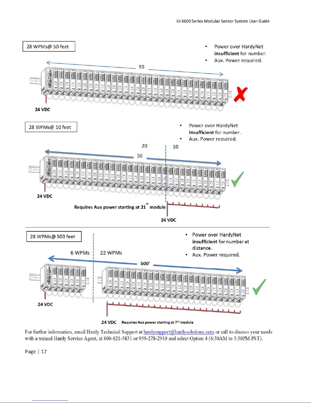
Power Requirements for Configuring Your Modular Sensor
System over Distance
Distributing power over Cat5e cabling to a fully loaded HI 6600 system (up to 28WPM units, up to 28 junction
boxes and up to 120 350 Ohm load cells) is beyond the current carrying ability of Cat5e cable.
Deploying a fully loaded system up to 500 feet poses no harm to the instrumentation or sensors. However, the
current required can prevent the system from discovering modules that do not have enough voltage available or
trip an over-current protection circuit until the condition is cleared.
Weight Processing Modules may require auxiliary power for systems consisting of a large number of channels
at large distances or that use non-Hardy load cells that have varied input resistances.
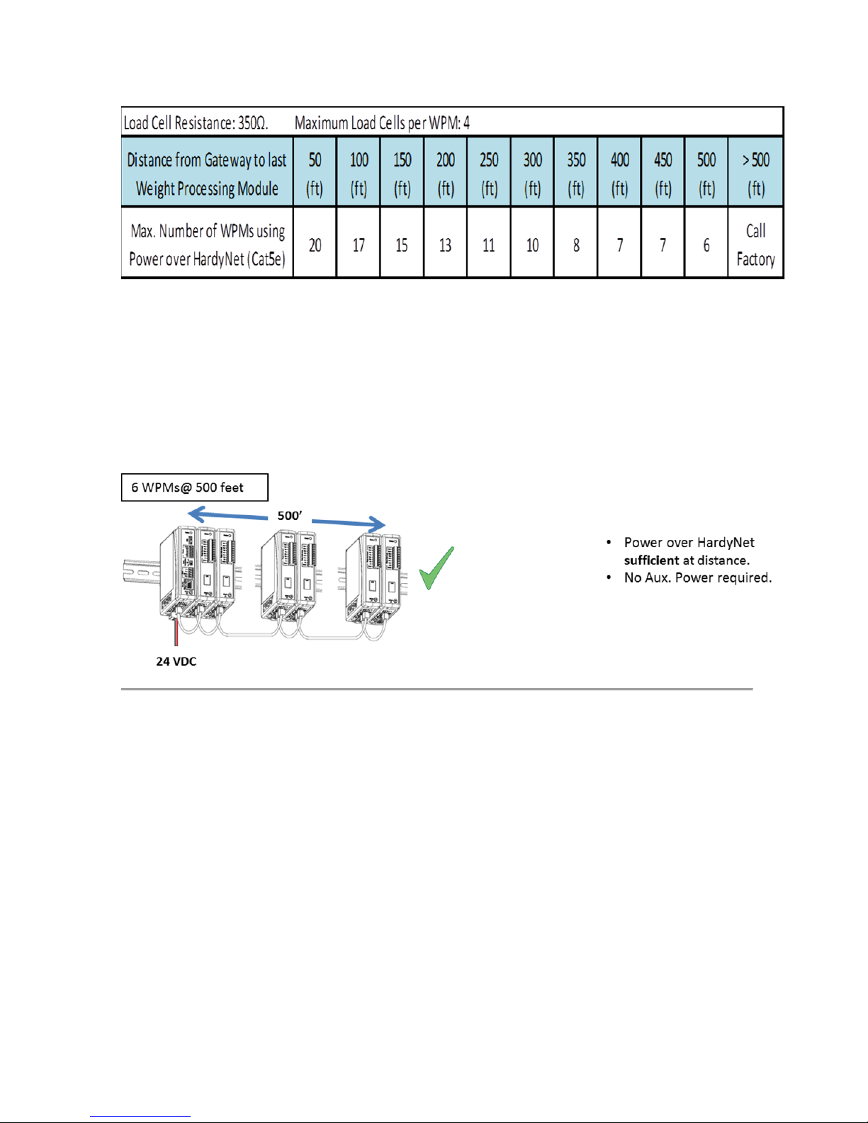
Below is table 1 showing the maximum number of units of specific distances running over Cat5e without any
additional power.
HI 6600 Series Modular Sensor System User Guide
Page | 15
Table 1: Maximum number of WPM Units at specific distances without Auxiliary Power
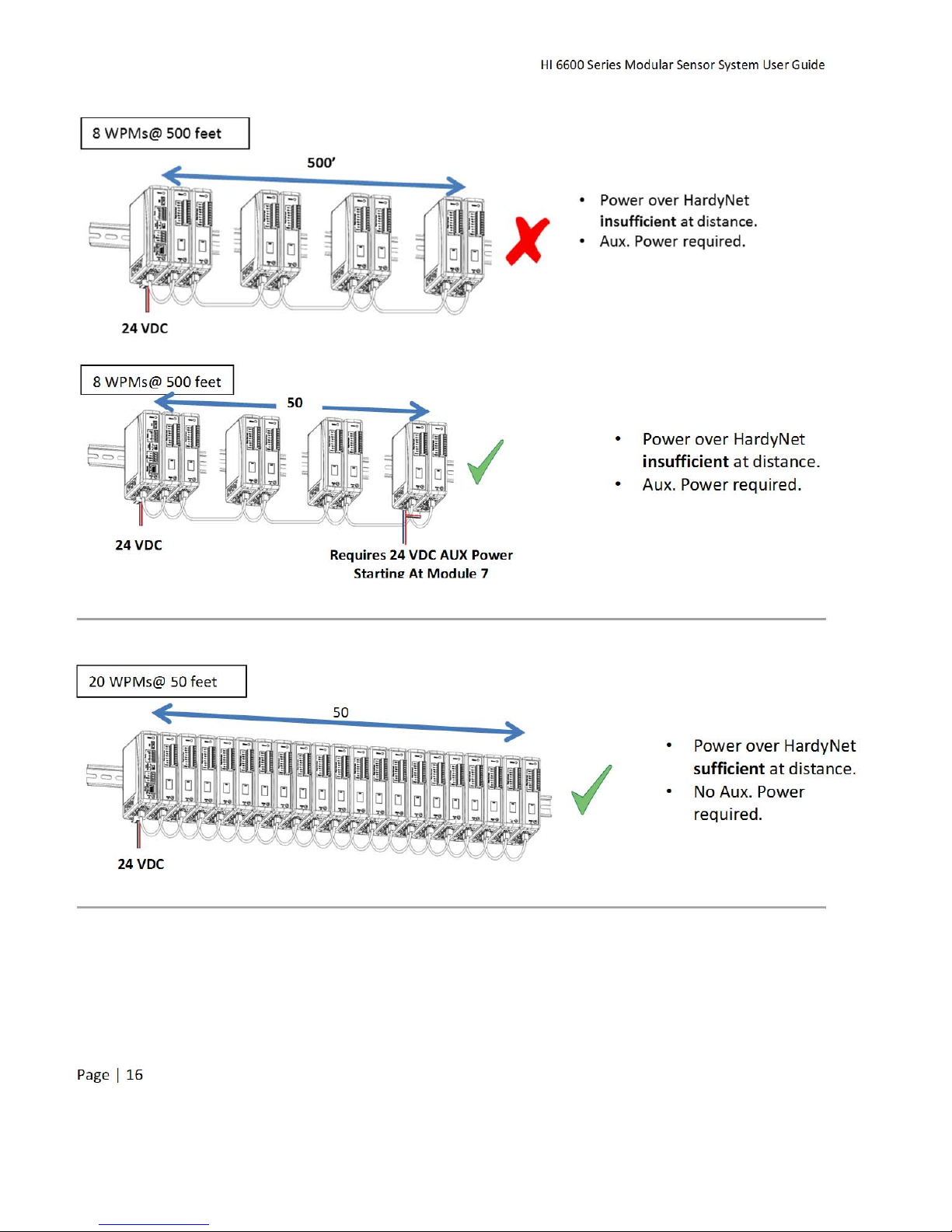
To add either distance or the maximum number of units, you will need to apply auxiliary power as shown in
the following configuration scenarios.
HI 6600 Series Modular Sensor System User Guide
Page | 16
HI 6600 Series Modular Sensor System User Guide
Page | 17
For further information, email Hardy Technical Support at hardysupport@hardysolutions.com or call to discuss your needs
with a trained Hardy Service Agent, at 800-821-5831 or 959-278-2910 and select Option 4 (6:30AM to 5:30PM PST).

HI 6600 Series Modular Sensor System User Guide
Page | 18
Chapter 3
HI 6600 Hardware Installation
• • • • • •
Chapter 3 covers physical installation of HI 6600 Modular Sensor System. User and service personnel should
read this chapter before installing or operating the HI 6600 Modular Sensor System.
Safety
Before you begin installing your HI 6600 series equipment, please review the important safety
precautions below.
Do not operate or work on this equipment unless you have read and understand the instructions and warnings
in this Manual. Failure to follow the instructions or heed the warnings could result in injury or death. Hardy
Process Solutions provides manuals in PDF format that are easily downloaded from our website, free of
charge. Look under the Docs & Programs tab on the web page for each product.
General Precautions
Always disconnect the power cord before disassembling.
Always replace broken or damaged modules or hardware immediately.
Always check to be sure that no loose parts are sitting on printed circuit boards or electrical
connectors or wires when disassembling or reassembling.
Always protect printed circuit boards from electrostatic discharge (ESD). Always use approved ESD
wrist straps and anti-static pads.
Unpacking
1) Before signing the packing slip, inspect the packaging for damage, and report damage of any kind to the
carrier company.
AVERTISSEMENT–Risqued’explosion– Ne pasdébrancherl’équipementà
moins que l’alimentation soit coupée ou que la zone ne présente pas de risques
WARNING - EXPLOSION HAZARD - DO NOT DISCONNECT EQUIPMENT
UNLESS POWER HAS BEEN SWITCHED OFF OR THE AREA IS KNOWN TO BE
NON-HAZARDOUS
AVERTISSEMENT–Risqued’explosion–Lasubstitutiondecomposantspeut
diminuerlaconformitépourlaDivision2
WARNING - EXPLOSION HAZARD - SUBSTITUTION OF COMPONENTS MAY
IMPAIR SUITABILITY FOR DIVISION 2.

HI 6600 Series Modular Sensor System User Guide
Page | 19
2) Checkto seethateverything in thepackage matchesthebill oflading.
3) If items are missing or you have any questions, contact Customer Service at:
Hardy Process Solutions
9440CarrollParkDrive
SanDiego,CA92121
Phone:(800)821-5831
International:(858)292-2710
FAX
:
(858) 278-6700
Web Site:
http//www.hardysolutions.com
E-Mail:
hardysupport@hardysolutions.com
Record the model number and serial number of the HI 6600 series instrument. Store them in a convenient,
secure location for reference when contacting Hardy Customer Service Department or to buy parts or firmware
upgrades.
Tool List
To install the HI 6600 series the following tools will be required.
Jewelers screw driver (to make and modify cable assemblies)
10-50 mm Unibit (for optional display installation)
Drill with 5mm drill bit (for optional display installation)
8 mm nut wrench or socket (for Optional Display)
Installing the HI 6610 Modules
Before getting started, take the following precautions:
Wear an approved wrist-strap grounding device when handling the instrument.
Touch a grounded object or surface to rid yourself of any electrostatic discharged prior to
handling the instrument.
Handle the instrument from the bezel in front away from the connector. Do not touch the
connector pins.
Do not install the instrument right next to an AC power source or high voltage DC equipment
Route all the low voltage cables away from high voltage cables
AVERTISSEMENT – Les décharges électrostatiques peuvent endommager les
composantssemi-conducteursdanslemodule.NETOUCHEZPASlesbrochesdu
connecteur.
WARNING- Electrostaticdischargemaydamagesemiconductorcomponentsin
the module. DO NOT TOUCH THE CONNECTOR PINS.
HI 6600 Series Modular Sensor System User Guide
Page | 20
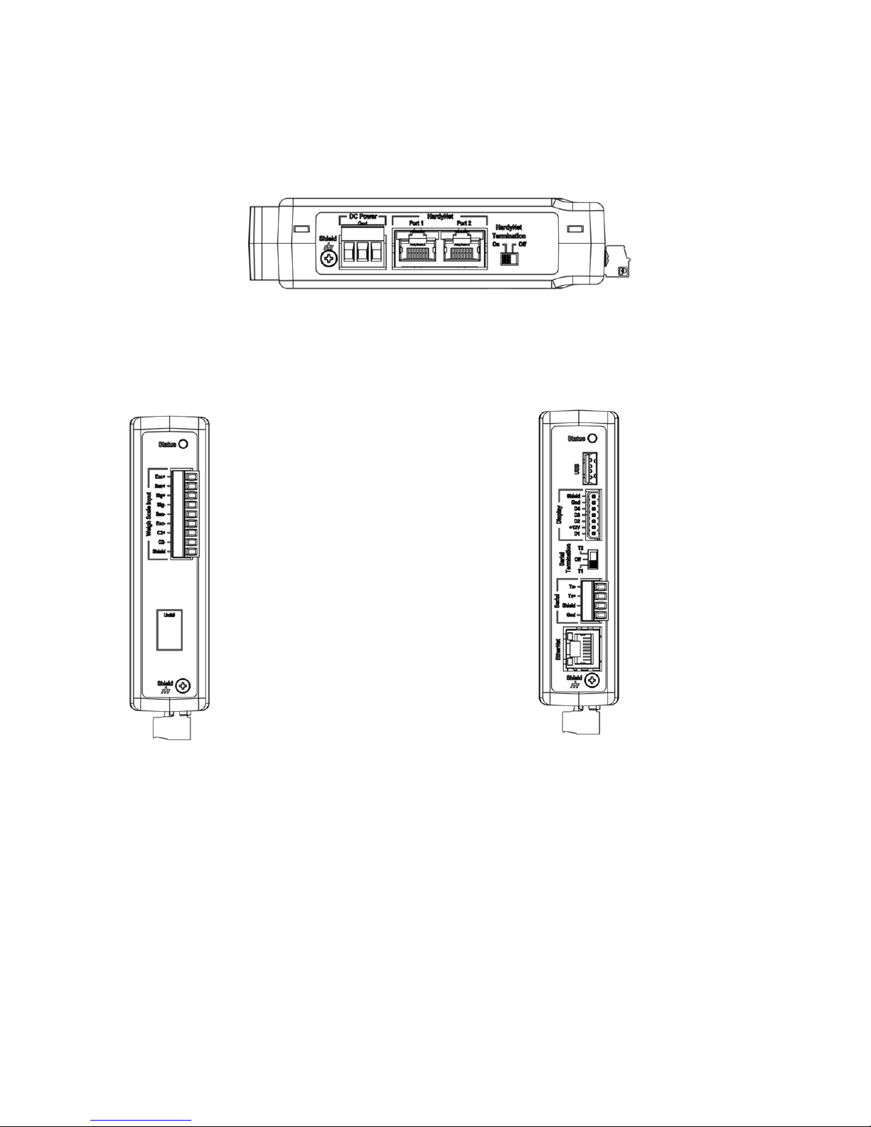
Overview of the HI 6600 Hardware
Before installing the HI 6600 Series, familiarize yourself with the basic configuration as shown below.
DC Power, Shield, Ports for HardyNet and a Termination switch can be found on the bottom of both the Hardy
Gateway Module and the Weight Processing Modules.
The RJ45 ports located on the bottom are used to connect the system using Cat5e cabling. Communications
between modules (HardyNet) as well as power distributed from the Gateway Module to the Weight Processing
Modules is carried on the Cat5e cabling.
Weight Processing Module Hardy Gateway Module
The Weigh Scale Input is located on the front of the HI 6610 Weight Processing Module.
Located on the front of the HI 6600 Gateway module is a USB port (used to store system settings), a Display
port (for connecting to an optional HI 6110 display), Serial Termination switch, Serial Port and an Ethernet
Port.
This manual suits for next models
3
Table of contents
Other Hardy Process Solutions Accessories manuals


