manuals.online logo
Brands
  1. Home
  2. •
  3. Brands
  4. •
  5. Harman
  6. •
  7. Keypad
  8. •
  9. Harman AMX MET-13 User manual

Harman AMX MET-13 User manual

This manual suits for next models

1

Other Harman Keypad manuals

Harman AMX MET-13E User manual

Harman

Harman AMX MET-13E User manual

Harman AMX Massio MCP-106 User manual

Harman

Harman AMX Massio MCP-106 User manual

Harman AMX MET-6N User manual

Harman

Harman AMX MET-6N User manual

Harman AMX Classic Series User manual

Harman

Harman AMX Classic Series User manual

Harman AMX MCP-106 User manual

Harman

Harman AMX MCP-106 User manual

Harman AMX Metreau MET-7 User manual

Harman

Harman AMX Metreau MET-7 User manual

Popular Keypad manuals by other brands

AAA 6150RFAAA Installation and setup guide

AAA

AAA 6150RFAAA Installation and setup guide

Fermax MDS Installation and programming manual

Fermax

Fermax MDS Installation and programming manual

ACT ACT PRO 1030 manual

ACT

ACT ACT PRO 1030 manual

Cardin SSB Series manual

Cardin

Cardin SSB Series manual

Harman Kardon KP 1 Specifications

Harman Kardon

Harman Kardon KP 1 Specifications

CYP CR-KP1 Operation manual

CYP

CYP CR-KP1 Operation manual

Aeware k-35 Series Quick reference card

Aeware

Aeware k-35 Series Quick reference card

Aritech CS-175 Series user guide

Aritech

Aritech CS-175 Series user guide

Lenze AC Tech MC SERIES installation instructions

Lenze AC Tech

Lenze AC Tech MC SERIES installation instructions

Burg Wächter secuENTRY 7711 operating instructions

Burg Wächter

Burg Wächter secuENTRY 7711 operating instructions

Aeware in.k450 Tech book

Aeware

Aeware in.k450 Tech book

Lenze EPM-H410 operating instructions

Lenze

Lenze EPM-H410 operating instructions

Toshiba RKP007Z user manual

Toshiba

Toshiba RKP007Z user manual

Elmes Electronic KB1 quick start guide

Elmes Electronic

Elmes Electronic KB1 quick start guide

Clare Controls ClareOne CLR-C1-PNC Installation sheet

Clare Controls

Clare Controls ClareOne CLR-C1-PNC Installation sheet

FM Electronics 4180 quick start guide

FM Electronics

FM Electronics 4180 quick start guide

AMX MIO-PRESTIGE-S Dimensional drawing

AMX

AMX MIO-PRESTIGE-S Dimensional drawing

why pro WHY-KP user manual

why pro

why pro WHY-KP user manual

manuals.online logo
manuals.online logoBrands
  • About & Mission
  • Contact us
  • Privacy Policy
  • Terms and Conditions

Copyright 2025 Manuals.Online. All Rights Reserved.

QUICK START GUIDE
MET-13 Metreau®13-Button Keypad
Overview
The MET-13 Metreau 13 Button keypad (FG5794-02) offers 13 buttons (12 single-
width, and 1 double-width) and can be used as in individual keypad or in conjunction
with the MET-6N and MET-7 Metreau keypads (FIG. 1).
The MET-13 is an AxLink keypad, suitable for use in NetLinx Control Systems.
Specifications
Installation
BhnurBefore touching the device, discharge the static electricity from your body by
touching a grounded metal object.
FIG. 2 shows the basic rear components of the MET-13 keypads:
AxLink Device Addressing
AxLink-enabled Metreau keypads use an 8-position mini-DIP switch to specify a unique
device address for each keypad in a NetLinx Control System.
Note: Before touching the device, discharge the static electricity from your body by
touching a grounded metal object.
1. If connected, disconnect the power supply.
2. Locate the 8-position mini-DIP switch on the rear panel.
3. Set the DIP switch according to the values shown in FIG. 3.
The device number is set by the total value of DIP switch positions that are in the ON
position. Note that the ON position is indicated on the DIP Switch.
As an example, the DIP switch in FIG. 3 defines AxLink device number 129
(1+128=129).
If you later change the device number, remove and reconnect the power connector to
enter the new device number into memory.
Wiring
Preparing captive wires
Caution: Do not connect power to the Metreau keypad until the wiring is complete.
Caution: If using power from AxLink, disconnect the wiring from the control system
before wiring the Metreau keypads.
You will need a wire stripper, and flat-blade screwdriver to prepare and connect the
captive wires.
1. Strip 0.25 inch (6.35 mm) of wire insulation off all wires.
2. Insert each wire into the appropriate opening on the connector according to the
wiring diagrams and connector types described in this section.
3. Turn the flat-head screws clockwise to secure the wires in the connector.
Note: Do not over-torque the screws; doing so can bend the seating pins and damage the
connector.
Wiring guidelines
Metreau keypads require 12 VDC power to operate properly. The necessary power is
supplied via the AxLink or SWT cable. The maximum wiring distance is determined by
power consumption, supplied voltage, and the wire gauge used for the cable. The
following table lists wire sizes and the maximum lengths allowable based on the
maximum power consumption rating of 170 mA.
FIG. 1 MET-13 METREAU 13-BUTTON KEYPAD
MET-13 SPECIFICATIONS
Power: 12 VDC, 30 mA
Front Panel
Components:
Pushbuttons - 13 tactile pushbuttons with blue LED indicators that
illuminate when pressed to confirm the source/function was
selected and that it is currently being used (12 single-width, 1
double-width). These pre-printed buttons are field-replaceable.
The bottom button functions as 2 buttons - there are 2 positions
(left and right) that allow the user to control channels (up/down).
Rear Panel
Components:
• DIP switch - 8-position mini DIP switch used to set the device
address for the keypad on the AxLink Bus (1-255).
• AxLink connector - 4-pin 3.5mm Phoenix connector for AxLink
connection to the NetLinx Master.
Dimensions
(HWD):
• Keypad and Mounting Plate: 4.055" x 1.772" x 0.818"
(103mm x 45mm x 207mm)
• Mounts into standard decora-style wall plates.
Weight: 2.4 oz. (68.04 g)
Operating
Environment:
• Operating Temperature: 32° - 104° F (0°- 40° C).
• Relative Humidity: 5% - 85%, non-condensing.
• Intended for indoor use only.
Certifications: • FCC Class B
•CE
• IEC60950
• RoHS
Colors: • White (FG5794-02-WH)
• Black (FG5794-02-BL)
• Light Almond (FG5794-02-LA)
Optional
Accessories:
• Single Button Kit (FG5794-10)
• Double Button Kit (FG5794-11)
• Lutron Cairo Wallplates (available in a variety of sizes and colors)
13 pre-printed pushbuttons
(with blue LED indicators)
2-position button
FIG. 2 MET-13 - REAR COMPONENTS
FIG. 3 8-POSITION MINI-DIP SWITCH
AXLINK WIRING GUIDELINES AT 170
MA
AxLink connector
(from NetLinx Controller)
Device Address
DIP Switch
Circuit Board
Mounting Plate
Switch
Value
12345678
1 2 4 8 16 32 64 128 Example
(129)
© 2015 Harman. All rights reserved. Metreau, NetLinx, Axcess, AMX, AV FOR AN IT WORLD, and HARMAN, and their respective logos are
registered trademarks of HARMAN. Oracle, Java and any other company or brand name referenced may be trademarks/registered trademarks
of their respective companies.
AMX does not assume responsibility for errors or omissions. AMX also reserves the right to alter specifications without prior notice at any time.
The AMX Warranty and Return Policy and related documents can be viewed/downloaded at www.amx.com.
3000 RESEARCH DRIVE, RICHARDSON, TX 75082 AMX.com | 800.222.0193 | 469.624.8000 | +1.469.624.7400 | fax 469.624.7153
AMX (UK) LTD, AMX by HARMAN - Auster Road, Clifton Moor, York, YO30 4GD United Kingdom • +44 1904-343-100 • www.amx.com/eu/
93-5794-02 REV: C
Last Revised: 7/31/2015
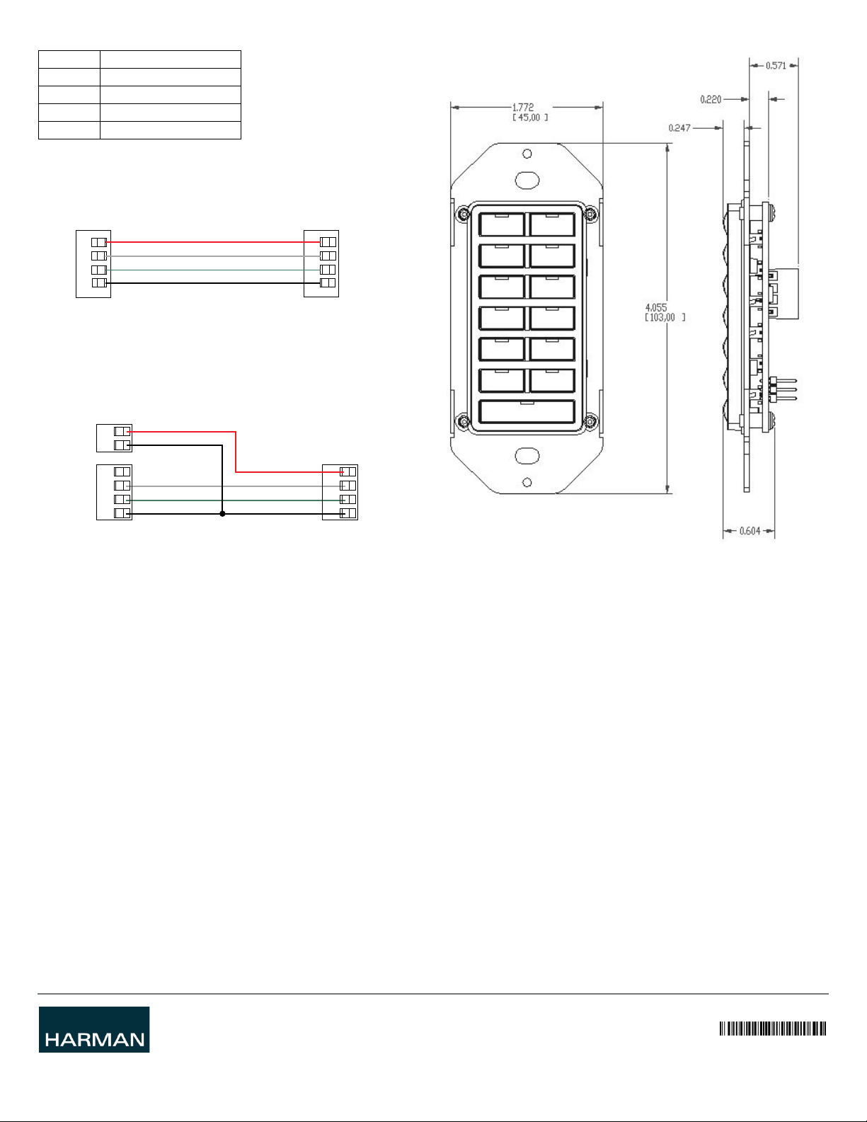
The maximum wiring lengths for using AxLink power are based on a minimum of 13.5
volts available. If the distance is greater than what is listed in the table, consult the
Metreau Keypads Operation/Reference Guide for wiring with external power sources.
AxLink Data and Power Connections
Connect the control system's AxLink connector to the AxLink connector on the rear
panel of the Metreau Keypad for data and 12 VDC power as shown in FIG. 4.
Using AxLink for Data with an Auxiliary Power Supply
Use an auxiliary 12 VDC power supply when the distance between the controller and
server exceeds the limits described in the Wiring guidelines section. Connect only the
GND (-) wire on the AxLink connector when using an auxiliary 12 VDC power supply.
Connect the NetLinx Controller’s AxLink connector to the AxLink connector on the rear
panel of the Metreau keypad, as shown in FIG. 5.
Note: If you are not using power from AxLink, disconnect the wiring from the controller
before wiring the Metreau keypad. Make sure the auxiliary power supply’s PWR (+) is not
connected to the controller’s AxLink connector.
AxLink Status LED
The AxLink Status LED (located next to the AxLink connector), lights to indicate AxLink
power/data status (see Operation / Reference Guide for details).
If the LED is on and not flashing, disconnect the AxLink connector and recheck all
AxLink connections. Then, reconnect the AxLink connector to the panel and verify the
LED is flashing once per second.
Mounting Procedures
AMX recommends mounting Metreau keypads in standard U.S.-style decora wallboxes:
• Conduit box should meet NEC specs (section 370)
• Minimum internal clearance of (HWD) 2-5/8" x 1-3/4" x 1-5/8".
Note: Before touching the device, discharge the static electricity from your body by
touching a grounded metal object.
Wallbox Mounting
1. Use the cutout dimension for the wallbox to cutout the install surface.
2. Connect the AxLink connector (or SWT cable connectors) to the rear of the
keypad.
3. Place the Mounting Plate on the wallbox; align the screw holes with the mounting
holes and fasten the Mounting Plate to the wallbox using the screws supplied.
Note: Do not overtighten the screws when mounting the Mounting Frame. The device
should be flush with mounting surface.
Mounting Dimensions
FIG. 6 provides detailed dimensions for the 13-button Metreau keypads.
Programming
There are a select number or SEND_COMMANDs the Metreau keypad recognizes. For a
full list and descriptions, consult the Metreau Keypads Operation/Reference Guide.
Sending Firmware to Metreau Keypads (AxLink)
The Firmware on the AxLink-enabled Metreau keypads (MET-6N, MET-7 and
MET-13) can be updated via the NetLinx Studio2 application:
Note: Refer to the NetLinx Studio 2 online help for additional details on firmware
transfers. NetLinx Studio 2 is available for free download from www.amx.com.
1. Open NetLinx Studio2.
2. Go to Tools > Firmware Transfers > Send to Axcess Device... This opens the Send
to Axcess Dialog Window.
3. Browse to the location of the firmware file.
4. Select the file within the Files frame.
5. Click Query for Devices.
6. Select the Metreau keypad within the Devices frame.
7. Click Send and then Close.
8. Upon confirmation of a successful send, you can exit NetLinx Studio2.
Additional Documentation
Refer to the Metreau Keypads Operation/Reference Guide (available online
www.amx.com) for additional information on configuration, programming and using the
Metreau keypads.
Wire Size Maximum Wiring Length
18 AWG 690.42 feet (210.43 m)
20 AWG 436.80 feet (133.13 m)
22 AWG 272.33 feet (83.00 m)
24 AWG 171.66 feet (52.32 m)
FIG. 4 AXLINK STRAIGHT-THRU WIRING
FIG. 5 AXLINK AND 12 VDC POWER SUPPLY WIRING DIAGRAM
PWR +
AXP
AXM
GND -
PWR +
AXP
AXM
GND -
Control System
Metreau Keypad
Metreau keypadNetLinx Controller
PWR (+)
GND (-)
PWR +
AXP
AXM
GND -
12 VDC power supply
PWR +
AXP
AXM
GND -
FIG. 6 MOUNTING DIMENSIONS - MET-13