manuals.online logo
Brands
  1. Home
  2. •
  3. Brands
  4. •
  5. Reer
  6. •
  7. Accessories
  8. •
  9. Reer R-Safe RRFID User manual

Reer R-Safe RRFID User manual

R-Safe RRFID 8541641 - Rev. 0 - 16/02/2023 QUICK INSTALLATION GUIDE
REER S.p.A. Via Carcano 32, 10153 Torino Italia 1
Tel. +39 0112482215 r.a. Fax +39 011859867
Sito web: www.reersafety.com - email: [email protected]
CONTENUTO IMBALLO
Sensore | Attuatore | Sensore+Attuatore RFID.
Tappi di sicurezza. Guida di installazione.
PACKAGE CONTENTS
RFID Sensor | Actuator | Sensor+Actuator.
Safety caps. Quick installation guide.
CONTENUE DE L’EMBALLAGE
Capteur | Actuateur | Capteur+Actuateur RFID.
Caps de sécurité. Guide d’installation.
PACKUNGSINHALT
RFID-Sensor | Aktuator | Sensor+Aktuator.
Sicherheitskappen. Installationsanleitung.
CONTENIDO DEL L’EMBALAJE
Sensor | Actuador | Sensor+Actuador RFID.
Tapones de seguridad. Guida de instalación.
Per installare e utilizzare in modo corretto e sicuroil sensore RFID, è
NECESSARIO consultare il manuale contenuto all’URL:
www.reersafety.com/QR/8541641
Toguarantee a correct and safe installation and operation of the RFID
sensor, it is MANDATORY to consultthe user manual contained atURL:
Pour installer et utiliser correctement et en sécurité le capteur RFID, il
est NECESSAIRE de consulter le manuel d’instruction, contenu à l'URL:
Um denRFID-Sensor korrekt und sicher zu installieren und zu
verwenden, MÜSSEN Sie das Handbuch unter der URL konsultieren:
Para instalary utilizar el sensor RFID deforma correcta y segura, DEBE
consultar el manual quese encuentra en la URL:
A) MONTAGGIO MECCANICO- MECHANICAL ASSEMBLY -MONTAGEMECANIQUE -BEFESTIGUNG -MONTAJEMECÁNICO
Precautions | ➔Important
Before installing the product, it is important to perform a specific risk analysis in accordance with the
requirements of the Machinery Directive (2006/42/EC).
REER guarantees the functional safety of R-Safe RFID but is not responsible for the performance of the system
in which it is installed.
Respect the correct activation direction described below.
Remove power supply from the product before proceeding with mechanical installation.
It is not permitted to fix sensor and actuator with less than two screws (EN ISO 14119).
Follow the installation rules described in the standard EN ISO 14119.
The use of anti-unscrewing screws is mandatory (EN ISO 14119).
Fasten the devices to the gate using M4 x 20 screws or alternatively 3.5 x 19 cylinderhead self-threading screws
with a tightening torque of 0.8 ... 1.5Nm.
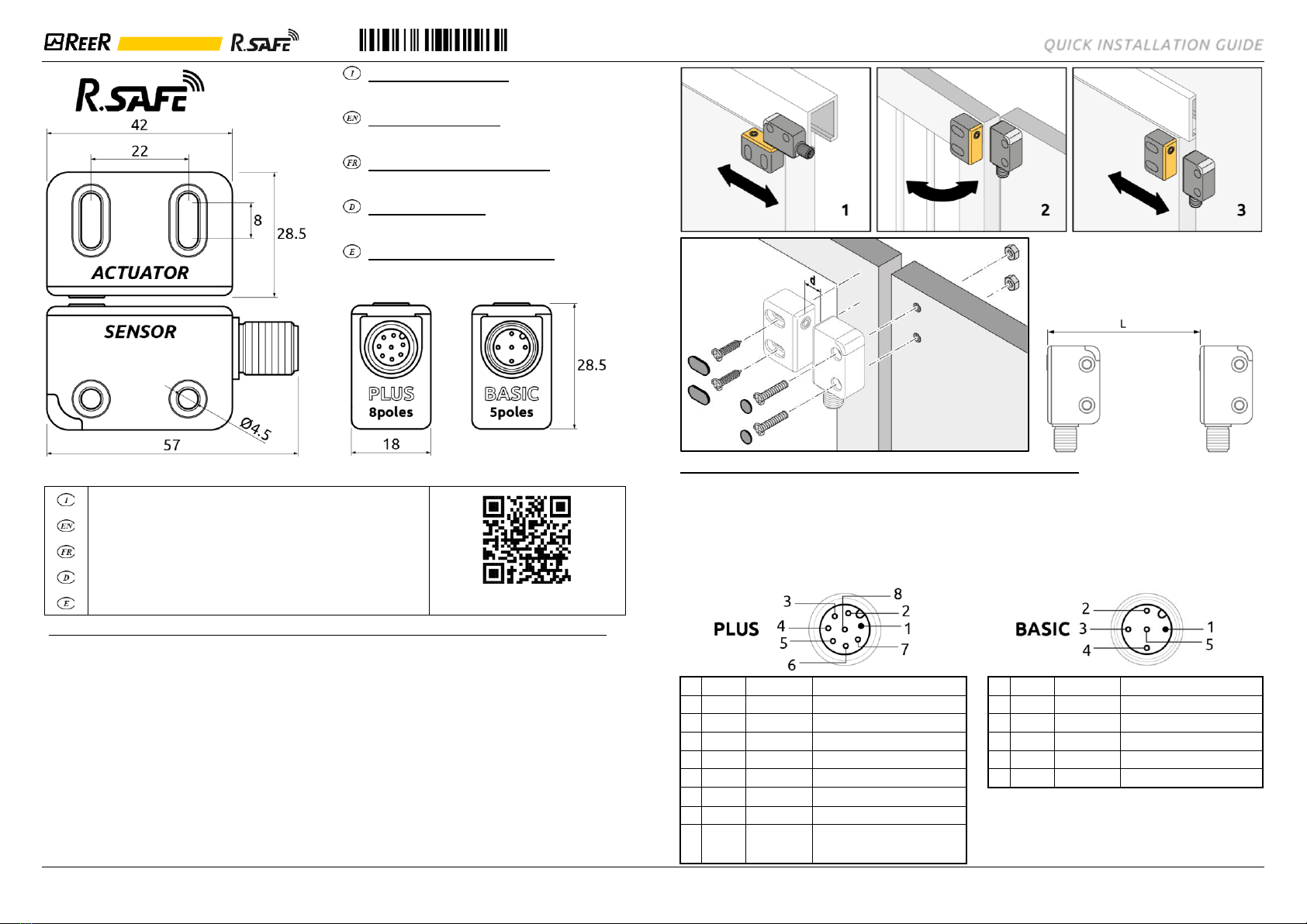
➔Mount the sensor to the fixed part of the safety gate/door and the actuator to the moving part.
➔At the end of the assembly, plug the supplied caps into the housing of the fixing screws as shown in the assembly
diagram. These plugs reduce the risk of tampering with the product as indicated in the EN ISO 14119 standard.
➔Place the sensor and actuator facing each other with the centering marks at a distance dcorresponding to:
Actuation direction 1: 6mm < d < 10mm | Actuation direction 2 and 3: 2mm < d < 10mm
(See following pictures for actuation direction and distance d)
➔Multiple systems | In the case of
applications involving multiple sensors
mounted close together, a minimum
distance L = 150mm between the sensors
must be observed in order to avoid
interference.
B) COLLEGAMENTI –CONNECTIONS–BRANCHEMENTS–ANSCHLÜSSE –CONEXIONES
➔Carry out all connections before supplying power to the product.
➔The ground connection (0VDC) must be common to all system components.
➔Make sure that the connector is screwed in all the way to ensure correct operation of the product.
➔The R-Safe RFID sensor must be supplied with a voltage of 24VDC +/- 20 % (IEC 60947-5-2).
➔Conductor size: 0.25 ... 2.5 mm2.
➔We recommend the use of separate power supplies for the product and for other electrical power equipment
(electric motors, inverters, frequency converters) or other sources of disturbance.
➔For connections longer than 20m, use cables with a cross-section of at least 0.5mm2 (AWG16), (1mm2 over 50m).
N.
COLOR
SIGNAL
DESCRIPTION
N.
COLOR
SIGNAL
DESCRIPTION
1
Brown
24VDC
24VDC power supply
1
Brown
24VDC
24VDC power supply
2
White
INPUT1
OSSD input for serial connection 1
2
White
OSSD1
Safety output OSSD1
3
Blue
0VDC
0VDC power supply
3
Blue
0VDC
0VDC power supply
4
Black
OSSD1
Safety output OSSD1
4
Black
OSSD2
Safety output OSSD2
5
Grey
STATUS
Sensor status output
5
Grey
STATUS
Sensor status output
6
Pink
INPUT2
OSSD input for serial connection 2
7
Violet
OSSD2
Safety output OSSD2
8
Orange
EDM/
RESTART/
SERIAL
Feedback K1K2 /
Restart /
Serial connection input
R-Safe RRFID QUICK INSTALLATION GUIDE
REER S.p.A. Via Carcano 32, 10153 Torino Italia 2
Tel. +39 0112482215 r.a. Fax +39 011859867
Sito web: www.reersafety.com - email: [email protected]
C) SCHEMIDICONNESSIONE –WIRINGDIAGRAMS–SCHÉMASÉLECTRIQUES–SCHALTPLÄNE–ESQUEMASDE CONEXIÓN
D) SEGNALAZIONI - STATUS INDICATORS - INDICATEURS - STATUSANZEIGEN - INDICADORES DE ESTADO
CONFIGURATION MODE(at power up)
COLOR
BLINKING
MEANING
YELLOWblinking
2times
SinglesensorwithEDMinAUTOmode
3times
SinglesensorwithoutEDMinAUTOmode
4times
Singlesensorin MANUALmode
5times
First sensorofserialconnection
6times
Sensorofserialconnection
NORMAL OPERATION
COLOR
SENSOR STATUS
MEANING
RED
BREAK
OSSDoutputsLOW
GREEN
GUARD
OSSDoutputsHIGH
YELLOW
RESTART
WaitingforRestart
GREEN /REDblinking
GUARD /INPUTOFF
Atleast onesensoris inBREAK state
GREEN blinking
PROGRAMMING
Actuatorprogramming (TEACH-IN)
YELLOWblinking
CONFIG
Configurationtype(see table above)
REDblinking
FAIL
Errorcondition(see following table)
E) DIAGNOSTICA - DIAGNOSTICS - DIAGNOSTIC - DIAGNOSE - DIAGNÓSTICO
CONFIGURATION MODE(at power up)
COLOR
BLINKING
ERROR(DIAGNOSTIC)
CORRECTIVEACTION
RED
blinking
1 time
OSSDoutputserror
Check OSSDconnections(4,7)
2times
Safety inputincongruency
Checksensorseriesconnections
(Input2,6/OSSD 4,7)
3times
EDMerror
CheckEDMconnections(8)
4times
Overvoltagedetected
Checkconnections/
Sendproductto ReeR
5times
Internalerror
Sendproductto ReeR
6times
Wrong transponder(actuator)
Replaceactuator
7times
Incorrect wire Configuration
Checkconnections
10 times
Antennaovervoltagedetected
Sendproductto ReeR
F) MODO SERIALE - SERIAL MODE - MODE SÉRIEUX - SERIENMODUS - MODO EN SERIE
G) ASSEGNAZIONENUOVOID-NEWIDASSIGNMENT-ATTRIBUTIONNOUVELID-ZUTEILUNGNEUEID-ASIGNACIÓNNUEVO ID
➔ONLY TEACH-IN MODEL - The sensor must be wired following the configuration in the diagram:
CONDITION A
CONDITION B
CONDITION C
Waiting for
power on.
Switched on,
waiting for
programming.
Actuator approaching
to sensor, programmed
and waiting for restart.
➔I valori di sicurezza, i dati tecnici, le condizioni di garanzia e la Dichiarazione di Conformità sono contenute integralmente nel manuale.
➔The safety values, technical data, warranty conditions and Declaration of Conformity are fully contained in the manual.
➔Les valeurs de sécurité, caractéristiques techniques les conditions de garantie et la Déclaration de Conformité sont contenues dans
le manuel dans leur intégralité.
➔Die Sicherheitswerte, Technische Daten, Garantiebedingungen und Konformitätserklärung sind vollständig im Handbuch enthalten.
➔Los valores de seguridad, datos técnicos, las condiciones de garantía y la Declaración de Conformidad se encuentran en el manual en
su totalidad.

Other Reer Accessories manuals

Reer PI M30 F User manual

Reer

Reer PI M30 F User manual

Reer PI M18 F User manual

Reer

Reer PI M18 F User manual

Reer MJBOX MJB1 User manual

Reer

Reer MJBOX MJB1 User manual

Reer PI SQ F-NF User manual

Reer

Reer PI SQ F-NF User manual

Reer Ulisse UNC User guide

Reer

Reer Ulisse UNC User guide

Reer 29020 User manual

Reer

Reer 29020 User manual

Reer PI M30 NF K User manual

Reer

Reer PI M30 NF K User manual

Reer ADMIRAL AD User manual

Reer

Reer ADMIRAL AD User manual

Reer ULISSE UPC User guide

Reer

Reer ULISSE UPC User guide

Popular Accessories manuals by other brands

Craftsman SNOW CAB 486.24276 Operator's manual

Craftsman

Craftsman SNOW CAB 486.24276 Operator's manual

Apogee Apogee Duet user guide

Apogee

Apogee Apogee Duet user guide

Omega Engineering DMD-480-S2 Series user manual

Omega Engineering

Omega Engineering DMD-480-S2 Series user manual

Fimar EasyLine Z3035 Use and maintenance

Fimar

Fimar EasyLine Z3035 Use and maintenance

Renkforce 1517030 operating instructions

Renkforce

Renkforce 1517030 operating instructions

Somogyi Elektronic Home NEA 1/WH instruction manual

Somogyi Elektronic

Somogyi Elektronic Home NEA 1/WH instruction manual

Joie Therma Insruction manual

Joie

Joie Therma Insruction manual

Promate 100 owner's manual

Promate

Promate 100 owner's manual

MSI MSI PEN user guide

MSI

MSI MSI PEN user guide

Transmitter Solutions iGAZER32P-10K/NC Instructional manual

Transmitter Solutions

Transmitter Solutions iGAZER32P-10K/NC Instructional manual

AUSTRALIAN MONITOR PAGENET 88 brochure

AUSTRALIAN MONITOR

AUSTRALIAN MONITOR PAGENET 88 brochure

ECA Intercept 2 Installation sheet

ECA

ECA Intercept 2 Installation sheet

Opticstar EQ700 instruction manual

Opticstar

Opticstar EQ700 instruction manual

Farnell KV112 user manual

Farnell

Farnell KV112 user manual

TEUFELBERGER CEclimb Manufacturer's information and instructions for use

TEUFELBERGER

TEUFELBERGER CEclimb Manufacturer's information and instructions for use

Moen Glass Shelf YB9490 Technical specifications

Moen

Moen Glass Shelf YB9490 Technical specifications

Openreach NTE5C User instructions

Openreach

Openreach NTE5C User instructions

Antelope Orion32 HD owner's manual

Antelope

Antelope Orion32 HD owner's manual

manuals.online logo
manuals.online logoBrands
  • About & Mission
  • Contact us
  • Privacy Policy
  • Terms and Conditions

Copyright 2025 Manuals.Online. All Rights Reserved.