Harvard Apparatus Panlab LE12404 Instructions for use
References:
LE12404 (76-0060)
Version:
V15/06/2015
Hardware User’s Manual
LE12404
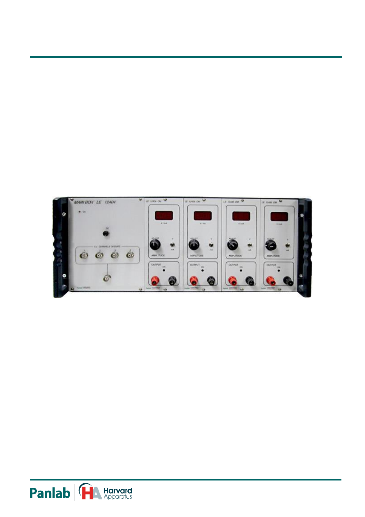
Mainframe for up to four LE12406OM units
Panlab, s.l.u
C/Energía, 112
08940 Cornellà de Ll.(Barcelona)
Spain
www.panlab.com
International Calls: +34 934 750 697
Domestic Call: 934 190 709
Fax: +34 934 750 699

Limitation of Liability
PANLAB does not accept responsibility, under any circumstances, for any harm or
damage caused directly or indirectly by the incorrect interpretation of what is
expressed in the pages of this manual.
Some symbols may have more than one interpretation by professionals
unaccustomed to their usage.
PANLAB reserves the right to modify, in part or in total, the contents of this document
without notice.
Mainframe for up to four LE 12406OM units
2
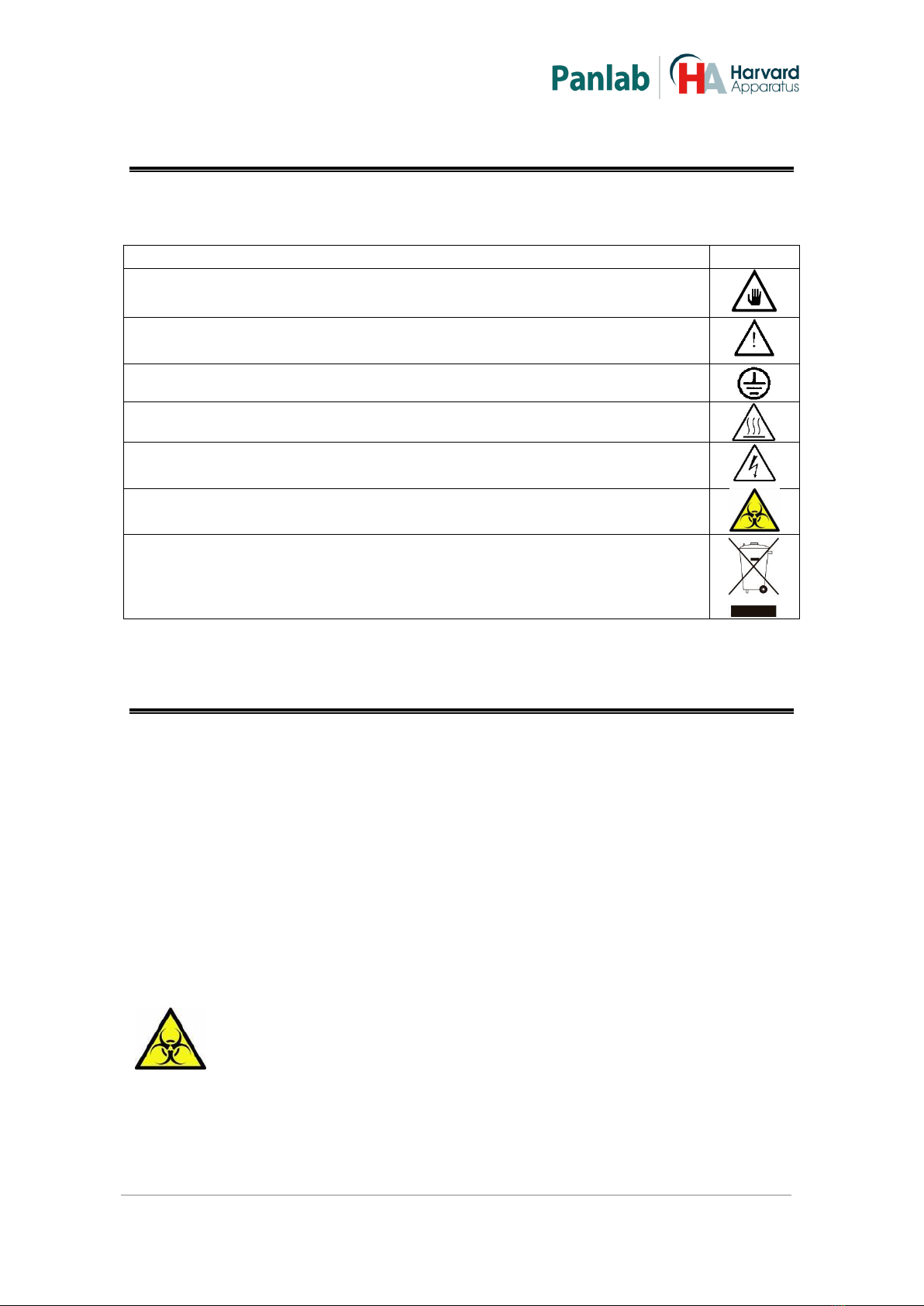
1. SYMBOLS TABLE
Recognising the symbols used in the manual will help to understand their meaning:
DESCRIPTION
SYMBOL
Warning about operations that must not be done because they can
damage the equipment
Warning about operations that must be done, otherwise the user can be
exposed to a hazard.
Protection terminal ground connection.
Warning about a hot surface which temperature may exceed 65ºC
Warning about a metal surface that can supply electrical shock when it’s
touched.
Decontamination of equipments prior to disposal at the end of their
operative life
Waste Electrical and Electronic Equipment Directive (WEEE)
2. GOOD LABORATORY PRACTICE
Check all units periodically and after periods of storage to ensure they are still fit for
purpose. Investigate all failures which may indicate a need for service or repair.
Good laboratory practice recommends that the unit be periodically serviced to ensure
the unit is suitable for purpose. You must follow preventive maintenance instructions.
In case equipment has to be serviced you can arrange this through your distributor.
Prior to Inspection, Servicing, Repair or Return of Laboratory Equipment the unit must
be cleaned and decontaminated.
Decontamination prior to equipment disposal
In use this product may have been in contact with bio hazardous materials
and might therefore carry infectious material. Before disposal the unit and
accessories should all be thoroughly decontaminated according to your
local environmental safety laws.
Mainframe for up to four LE 12406OM units
3
3. UNPACKING AND EQUIPMENT INSTALATION
WARNING: Failure to follow the instructions in this section may
cause equipment faults or injury to the user.
A. No special equipment is required for lifting but you should consult your local
regulations for safe handling and lifting of the equipment.
B. Inspect the instrument for any signs of damage caused during transit. If any
damage is discovered, do not use the instrument and report the problem to
your supplier.
C. Ensure all transport locks are removed before use. The original packing has
been especially designed to protect the instrument during transportation. It is
therefore recommended to keep the original carton with its foam parts and
accessories box for re-use in case of future shipments. Warranty claims are
void if improper packing results in damage during transport.
D. Place the equipment on a flat surface and leave at least 10 cm of free space
between the rear panel of the device and the wall. Never place the equipment
in zones with vibration or direct sunlight.
E. Once the equipment is installed in the final place, the main power switch must
be easily accessible.
F. Only use power cords that have been supplied with the equipment. In case that
you have to replace them, the spare ones must have the same specs that the
original ones.
G. Make sure that the AC voltage in the electrical network is the same as
the voltage selected in the equipment. Never connect the equipment to a
power outlet with voltage outside these limits.
The manufacturer accepts no responsibility for improper use of the equipment or the
consequences of use other than that for which it has been designed.
WARNING
For electrical safety reasons you only can connect equipment to
power outlets provided with earth connections .
This equipment can be used in installations with category II over-
voltage according to the General Safety Rules.

Mainframe for up to four LE 12406OM units
4
WARNING
PC Control
Some of these instruments are designed to be controlled from a PC. To
preserve the integrity of the equipment it is essential that the attached PC
itself conforms to basic safety and EMC standards and is set up in
accordance with the manufacturers’ instructions. If in doubt consult the
information that came with your PC. In common with all computer
operation the following safety precautions are advised.
• To reduce the chance of eye strain, set up the PC display with the correct
viewing position, free from glare and with appropriate brightness and
contrast settings
• To reduce the chance of physical strain, set up the PC display, keyboard
and mouse with correct ergonomic positioning, according to your local
safety guidelines.
Mainframe for up to four LE 12406OM units
5
4. MAINTENANCE
WARNING: Failure to follow the instructions in this section may cause
equipment fault.
PRESS KEYS SOFTLY –Lightly pressing the keys is sufficient to activate them.
Equipments do not require being disinfected, but cleaned for removing urine,
faeces and odour. To do so, we recommend using a wet cloth or paper with soap
(which has no strong odour). NEVER USE ABRASIVE PRODUCTS OR
DISSOLVENTS.
NEVER pour water or liquids on the equipment.
Once you have finished using the equipment turn it off with the main switch. Clean
and check the equipment so that it is in optimal condition for its next use.
The user is only authorised to replace fuses with the specified type when necessary.
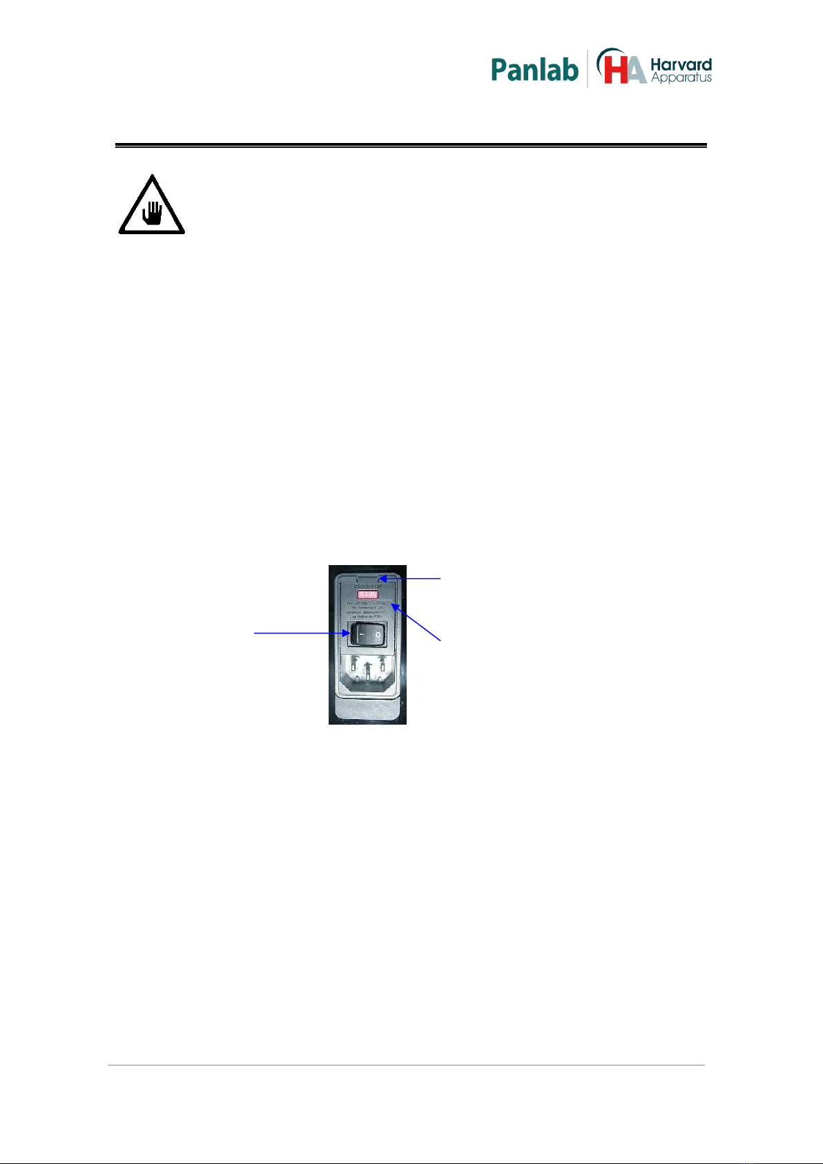
Figure 1. Power inlet, main switch and fuse holder.
FUSE REPLACEMENT OR VOLTAGE SETTING CHANGE
In case of an over-voltage or other incident in the AC net making it impossible to turn
on the equipment, or if the equipment voltage setting is incorrect, check fuses
according to the following procedure.
1
Remove power cord from the power inlet.
SWITCH
FUSE-HOLDER
OPENING FLANGE

Mainframe for up to four LE 12406OM units
6
2
Open fuse-holder by pulling the
flange with a regular
screwdriver.
Figure 2. Open fuse-holder door.
3
Extract fuse holder using the
screwdriver.
Figure 3. Extract fuse-holder.
4
Replace fuses if necessary. Insert fuses in the fuse-holder in the correct position.
CORRECT
INCORRECT
Figure 4. Fuses position.
5
Insert the fuse-holder again, positioning it according to the voltage in the AC net.
115V POSITON
230V POSITION
Figure 5 Fuse holder position.
6
If the fuses blow again, unplug the equipment and contact technical service.
WARNING
For electrical safety reasons, never open the equipment. The power
supply has dangerous voltage levels.

Mainframe for up to four LE 12406OM units
7
5. TABLE OF CONTENTS
1. SYMBOLS TABLE 2
2. GOOD LABORATORY PRACTICE 2
3. UNPACKING AND EQUIPMENT INSTALATION 3
4. MAINTENANCE 5
5. TABLE OF CONTENTS 7
6. INTRODUCTION 8
7. EQUIPMENT DESCRIPTION 9
7.1. CONTROL UNIT FRONT PANEL 9
7.2. CONTROL UNIT REAR PANEL 12
8. EQUIPMENT CONNECTION 13
9. WORKING WITH THE EQUIPMENT 14
9.1. TIME BASE 14
9.2. POWER MODULE 14
9.3. ELECTRODES CLEANING 14
10. TROUBLESHOOTING 15
11. PREVENTIVE MAINTENANCE 16
12. TECHNICAL SPECIFICATIONS 17

Mainframe for up to four LE 12406OM units
8
6. INTRODUCTION
The Digital Stimulator LE1404 is an instrument which provides a wide range of
stimulation with single/repetitive pulses of selectable constant voltage/current. The
LE 12404 has not time base it has BNC connectors to interface with an external time
base device.
A carefully designed and self–explanatory set of front panel controls make easy the
full control of the stimulation parameters, and makes this model ideal for middle
range applications.
Figure 6. LE 12404 Digital Stimulator.
The OUTPUT of the stimulation pulses is electrically floating from Ground, that is, it
does not refer to Ground. In order to avoid the appearance of parasite signals and
frequencies (50 or 60 Hz), it is necessary to keep in mind some precautions, as could
be either not to “connect” the stimulated subject to Ground or to the metallic surface
in contact with the subject.
It is something clear that it is not strictly necessary to take the aforementioned
precautions, because it depends on the nature of the external electric conditions what
determines the appearance or not of the interferences. Otherwise, BNC connectors,
have their negative connected to Ground to monitor signal in case it was necessary.
WARNING: Do not touch the electrodes when the stimulator is working,
you may receive electrical shock.
Mainframe for up to four LE 12406OM units
9
7. EQUIPMENT DESCRIPTION
7.1. CONTROL UNIT FRONT PANEL
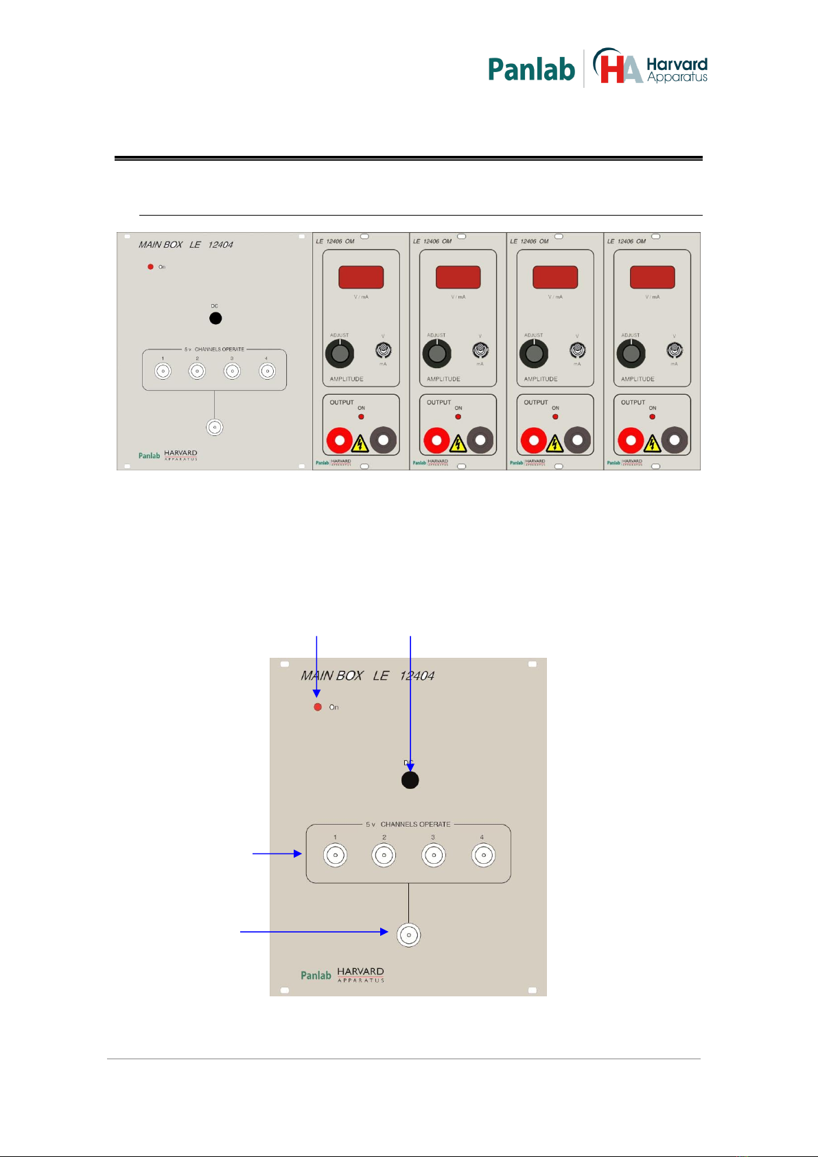
Figure 7. LE 12404 Front panel.
LE 12404 has not time base, it has 4 power modules and a panel with 4 BNC
connectors to activate each power module, and a fifth BNC connector to activate the
4 power modules at the same time. These BNC connectors are thought to be
connected to an external TTL time generator so that complex stimulation patterns
can be applied to tissue.
Figure 8. Main Box LE 12404.
ON DC
INDEPENDENT
CHANNELS
ALL
CHANNELS
Mainframe for up to four LE 12406OM units
10
ON: 3mm red coloured led that is on when you turn on the stimulator.
DC: You will obtain continuous output in the power modules while you press
this button.
INDEPENDENT CHANNELS: There are 4 BNC connectors; one for each power
module, the purpose of these BNC connectors is connect the stimulator to an
external TTL timing generator that will replace the time base module.
ALL CHANNELS: This BNC connector will activate the 4 power modules at the
same time, with the TTL signal of an external time generator.
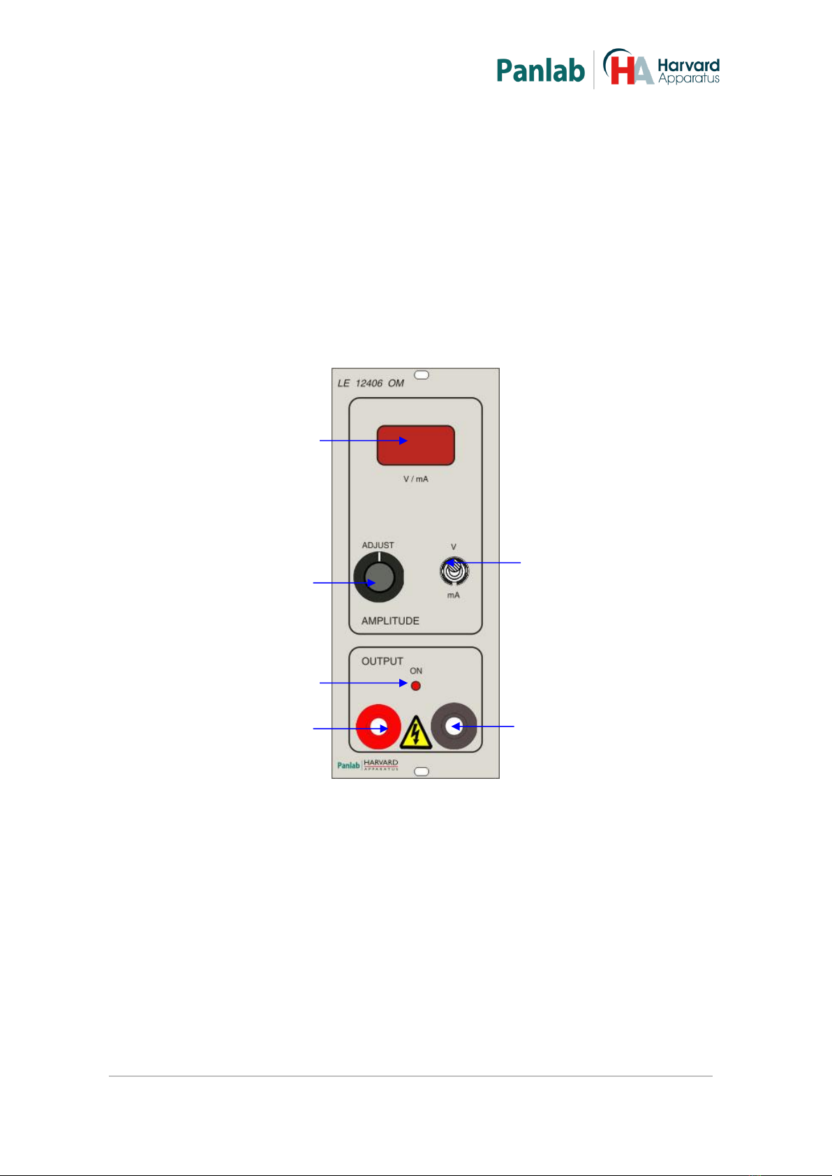
Figure 9. Power module.
V/mA Display: Displays the amplitude of the voltage pulses between 0 and
100V or current pulses between 0 and 500 mA.
V/mA switch: 2-position switch to select the mode (voltage/current).
oUpper position: Sets the system in voltage mode.
oLower Position: Sets the system in current mode.
Adjust: Potentiometer that sets the amplitude of voltage/current between 0V
and 100V or 0 mA and 500 mA.
V/mA Display
ADJUST
ON
Output +
V/mA switch
Output -

Mainframe for up to four LE 12406OM units
11
ON: Two-colour led. When the output is active, it is green and blinks to the
frequency of pulses. An overload is indicated when the led is red. The system
enters overload state when there is a short-circuit in the output or output
power is higher than module power for 3 minutes. In overload state there are
no pulses in the output. To exit from overload state, solve the cause of the
problem and wait for around seven minutes.
Output +: Output positive terminal.
Output -: Output negative terminal.

Mainframe for up to four LE 12406OM units
12
7.2. CONTROL UNIT REAR PANEL
Figure 10. LE 12404 Rear Panel.
POWER: Main switch, power inlet and fuse holder.
POWER
Mainframe for up to four LE 12406OM units
13
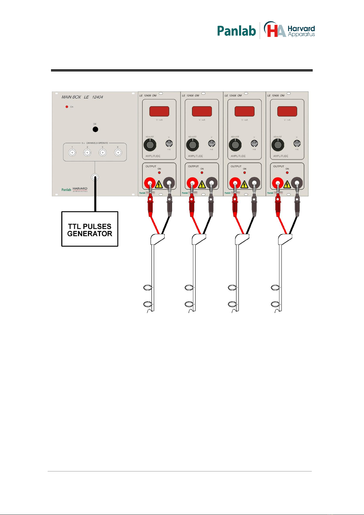
8. EQUIPMENT CONNECTION
Figure 11. LE 12404 connection.
Just connect the electrodes to both positive and negative outputs of each Power
Module. You will need an external TTL time generator to activate the 4 power
modules simultaneously with the common BNC connector, or 4 independent TTL time
generators to activate each power module independently.

Mainframe for up to four LE 12406OM units
14
9. WORKING WITH THE EQUIPMENT
9.1. TIME BASE
The LE 12404 has not time base as the other models of stimulators, it has a panel with
5 BNC connectors. Four of them control each one a Power Module and the fifth one
controls the 4 power modules at the same time.
An external TTL pulse generator has to be connected to the BNC connectors in order
to generate the stimulation pulses.
There is a button labelled on the BNC connector’s panel. This button is used
to obtain a continuous output while it remains pressed in all power modules at the
same time.
9.2. POWER MODULE
There are controls in the power module to select the kind of output (voltage or
current) and the amplitude of pulses. With the V/mA switch, choose voltage or
current output.
With the potentiometer you can select the amplitude of pulses from 0V to 100V
in voltage mode or 0 mA to 500 mA in current mode. The value of the amplitude can
be seen on the display .
9.3. ELECTRODES CLEANING
After each experiment the electrodes must be cleaned to remove traces of salts
attached to them, to clean them you can dip them in distilled water and with a soft
brush remove residual salts attached to them being careful in order not to damage the
terminals of the electrodes.
You can also use an ultrasonic bath to remove salts remaining attached to the
electrodes.

Mainframe for up to four LE 12406OM units
15
10. TROUBLESHOOTING
This table features instructions to solve the most frequent problems.
PROBLEM
SOLUTION
The equipment does not start up.
Ensure that the voltage of mains is
the same as that selected in the fuse
holder.
Check the condition of the fuses.
The LED ON is red and there are not
power pulses.
This occurs when there is an
overload, a thermal switch to protect
the circuit is triggered by cancelling
the output. You must disconnect the
load and wait a few minutes until the
output transistor to cool sufficiently
to reset the power module (the red
LED turns off).
The power module does not give
pulses
Check that the related BNC
connector is connected to the
external pulse generator.
Check that the ON led is not in red
colour (overload protection).

Mainframe for up to four LE 12406OM units
16
11. PREVENTIVE MAINTENANCE
EXPERIMENT
ELECTRODES CLEANING
ELECTRODES CONNECTION
CHECKING

Mainframe for up to four LE 12406OM units
17
12. TECHNICAL SPECIFICATIONS
POWER SUPPLY
Input voltage:
Frequency:
Fuse:
Maximum Power:
Conducted Noise:
115/ 230V~
50 /60 Hz
2 fuses 5x20mm 2 A 250V Fast
110W
EN55022 /CISPR22/CISPR16 class B
ENVIRONMENTAL CONDITIONS
Operating temperature:
Operating Relative Humidity:
Storage temperature:
10°C to +40°C
0% to 85% RH, non-condensing
0°C to +50°C, non-condensing
POWER MODULE:
Voltage Range:
Voltage mode overload
Current Range:
Output Power
0V to 100V
540mA
0mA to 500mA
50W maximum @ 3 minutes
BNC CONNECTORS
On level:
Off level:
5V
0V
DIMENTIONS
Width x Height x Depth:
Weight:
415mm x 190mm x 350 mm
11kg

Mainframe for up to four LE 12406OM units
18
DECLARACIÓN DE CONFORMIDAD
DECLARATION OF CONFORMITY
DECLARATION DE CONFORMITÉ
Nombre del fabricante:
Manufacturer’s name:
Nom du fabricant:
Dirección del fabricante:
Manufacturer’s address:
Adresse du fabricant:
Energía, 112
08940 Cornellà de Llobregat
Barcelona SPAIN
Declara bajo su responsabilidad que el producto:
Declares under his responsibility that the product:
Déclare sous sa responsabilité que le produit:
DIGITAL STIMULATOR
Marca / Brand / Marque:
PANLAB
Modelo / Model / Modèle:
LE 12404
Cumple los requisitos esenciales establecidos por la Unión Europea en las directivas siguientes:
Fulfils the essential requirements established by The European Union in the following directives:
Remplit les exigences essentielles établies pour l’Union Européenne selon les directives suivantes:
2006/95/EC
2004/108/EC
2012/19/EU
2011/65/EU
2006/42/EC
Directiva de baja tensión / Low Voltage / Basse tensión
Directiva EMC / EMC Directive / Directive CEM
La Directiva de Residuos de Aparatos Eléctricos y Electrónicos (WEEE) /
The Waste Electrical and Electronic Equipment Directive (WEEE) / Les
déchets d'équipements électriques et électroniques (WEEE)
Restricción de ciertas Sustancias Peligrosas en aparatos eléctricos y
electrónicos (ROHS) / Restriction of the use of certain Hazardous
Substances in electrical and electronic equipment (ROHS) / Restriction de
l'utilisation de certaines substances dangereuses dans les équipements
électriques et électroniques (ROHS)
Directiva mecánica / Machinery directive / Directive mécanique
Para su evaluación se han aplicado las normas armonizadas siguientes:
For its evaluation, the following harmonized standards were applied:
Pour son évaluation, nous avons appliqué les normes harmonisées suivantes:
Seguridad / Safety / Sécurité: EN61010-1:2011
EMC: EN61326-1:2013 Class B
Safety of machinery: EN ISO 12100:2010
En consecuencia, este producto puede incorporar el marcado CE:
Consequently, this product can incorporate the CE marking:
En conséquence, ce produit peut incorporer le marquage CE:
En representación del fabricante:
Manufacturer’s representative:
En représentation du fabricant:
Carme Canalís
General Manager
Panlab s.l.u., a division of Harvard BioScience
Cornellà de Llobregat, Spain
30/04/2014
Mainframe for up to four LE 12406OM units
19
Table of contents
Other Harvard Apparatus Laboratory Equipment manuals


Popular Laboratory Equipment manuals by other brands

CertoClav
CertoClav Connect operating manual

Beckman Coulter
Beckman Coulter CD103-FITC manual

UGO BASILE
UGO BASILE 37000-006 Assembly instruction

Cascade Sciences
Cascade Sciences CVO-2-HT Installation and operation manual

Sellstrom
Sellstrom MONITOR 2000 Installation, operation & maintenance manual

Showa Denko
Showa Denko Shodex Asahipak GF-HQ Series Operation manual


Kodak
Kodak X-Omat 480 RA installation instructions

Baltech
Baltech OA-5000 Operation manual

IKA
IKA MS 450 Swirler operating instructions

erlab
erlab Captair Store Midcap AVPD 804 Assembly instructions

Dionex
Dionex P680 Quick installation guide

National Instruments
National Instruments SCXI-1141 CALIBRATION PROCEDURE