manuals.online logo
Brands
  1. Home
  2. •
  3. Brands
  4. •
  5. SMC Networks
  6. •
  7. Industrial Equipment
  8. •
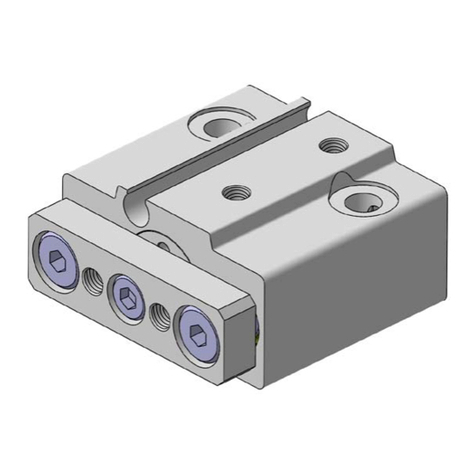
  9. SMC Networks LVD Series User manual

SMC Networks LVD Series User manual

This manual suits for next models

4

Other SMC Networks Industrial Equipment manuals
SMC Networks IT Series User manual

SMC Networks

SMC Networks IT Series User manual

SMC Networks CY3B Series User manual

SMC Networks

SMC Networks CY3B Series User manual

SMC Networks JMHZ2-16D-X7400B-CRX User manual

SMC Networks

SMC Networks JMHZ2-16D-X7400B-CRX User manual

SMC Networks ZXP7 Series User manual

SMC Networks

SMC Networks ZXP7 Series User manual

SMC Networks KFG2 Series User manual

SMC Networks

SMC Networks KFG2 Series User manual

SMC Networks IBG Series User manual

SMC Networks

SMC Networks IBG Series User manual

SMC Networks EX260-SEN1-X242 User manual

SMC Networks

SMC Networks EX260-SEN1-X242 User manual

SMC Networks CYV Series User manual

SMC Networks

SMC Networks CYV Series User manual

SMC Networks CS2 User manual

SMC Networks

SMC Networks CS2 User manual

SMC Networks MGJ Series User manual

SMC Networks

SMC Networks MGJ Series User manual

SMC Networks VQ2000 Series User manual

SMC Networks

SMC Networks VQ2000 Series User manual

SMC Networks MSZ Series User manual

SMC Networks

SMC Networks MSZ Series User manual
SMC Networks ZSE50F User manual

SMC Networks

SMC Networks ZSE50F User manual

SMC Networks MHR3-10 User manual

SMC Networks

SMC Networks MHR3-10 User manual

SMC Networks AS Series User manual

SMC Networks

SMC Networks AS Series User manual

SMC Networks ZL3 Series User manual

SMC Networks

SMC Networks ZL3 Series User manual

SMC Networks XT316-30(B) User manual

SMC Networks

SMC Networks XT316-30(B) User manual

SMC Networks ZSE20C Series User manual
SMC Networks

SMC Networks ZSE20C Series User manual

SMC Networks MGC Seires User manual

SMC Networks

SMC Networks MGC Seires User manual

SMC Networks ZQ Series User manual

SMC Networks

SMC Networks ZQ Series User manual

SMC Networks VR2110 User manual

SMC Networks

SMC Networks VR2110 User manual

SMC Networks PSE550 User manual

SMC Networks

SMC Networks PSE550 User manual

SMC Networks HEBC002-WA10 User manual

SMC Networks

SMC Networks HEBC002-WA10 User manual

SMC Networks MXJ Series User manual

SMC Networks

SMC Networks MXJ Series User manual

Popular Industrial Equipment manuals by other brands

ABB +Q957 user manual

ABB

ABB +Q957 user manual

G.B.C BASIC EDGE 50 instruction manual

G.B.C

G.B.C BASIC EDGE 50 instruction manual

Tronair Batpak 11-6602-1000 Operation & service manual

Tronair

Tronair Batpak 11-6602-1000 Operation & service manual

Pilz PNOZ mi2p Operation manual

Pilz

Pilz PNOZ mi2p Operation manual

Clemco Zero BNP 6012 manual

Clemco

Clemco Zero BNP 6012 manual

Erskine Attachments V-Plow Operator's manual

Erskine Attachments

Erskine Attachments V-Plow Operator's manual

ABB HT610965 Operation manual

ABB

ABB HT610965 Operation manual

Morra MH 540 user manual

Morra

Morra MH 540 user manual

Eaton S090ST manual

Eaton

Eaton S090ST manual

GRIGGIO G 240 P4 instructions

GRIGGIO

GRIGGIO G 240 P4 instructions

Nexen AIR CHAMP HT45 user manual

Nexen

Nexen AIR CHAMP HT45 user manual

WTE V5 installation manual

WTE

WTE V5 installation manual

ABB HT845232 Operation manual

ABB

ABB HT845232 Operation manual

JohnDow Industries JDI-AFT58 Operator's manual

JohnDow Industries

JohnDow Industries JDI-AFT58 Operator's manual

IMB MB9016A instruction manual

IMB

IMB MB9016A instruction manual

Clarke CUMB1 Assembly & operating instructions

Clarke

Clarke CUMB1 Assembly & operating instructions

amiad Arkal Spin Klin 2 user guide

amiad

amiad Arkal Spin Klin 2 user guide

Maxima GIUNTOMAX Use and maintenance manual

Maxima

Maxima GIUNTOMAX Use and maintenance manual

manuals.online logo
manuals.online logoBrands
  • About & Mission
  • Contact us
  • Privacy Policy
  • Terms and Conditions

Copyright 2025 Manuals.Online. All Rights Reserved.

High Purity Chemical Valve
Compact Type
Space saving, compact type is available.
Compact type is introduced as a new series to complement
conventional Series LVC with integral fittings.
Select a series according to the flow rate and
installation requirements.
Mounting base dimensions conform to SEMI
Standard, F65-1101. (Except for LVD10)
Body:
New
PFA
Diaphragm:
PTFE
Actuator section:
PPS
Body:
New
PFA
Diaphragm:
PTFE
Actuator section:
PPS
Body:
New
PFA
Diaphragm:
PTFE
Actuator section:
PPS
Space saving, compact type is available.
Class2
LVC20
54.5
79
LVD20
54.5
67
Class3
79
106
LVD30
79.5
83
Class4
96
131
LVC40
LVD40
82
93
Class5
LVC50
129
154
LVD50
105.5
114
A
B
(mm)
Dimension across inlet/
outlet ports: Reduced by up to
29
%
Dimension across inlet/
outlet ports: Reduced by up to
29
%
A
LVC
B
LV D
qe
w
r
Body
Actuator section
Integral clean one-touch fitting construction
(Series KP is used.)
Can select female thread (M5 x 0.8).
Piping from 4 directions are possible.
(Made to Order)
Integral fittings construction
HYPER FITTING®‚
Series LQ1 is used.
Series LVD
Integral tubing (construction)
CAT.ES70-24 -UK
A
LVC30
2
4
8
10
16
LVD10
LVD20
LVD30
LVD40
LVD50
2.1
(0.09)
8.4
(0.35)
346810 12 19 25 1/8 3/16 1/4 3/8 1/2 3/4 1
31.2
(1.3)
45.6
(1.9)
120
(5)
Applicable tubing size
Metric size Inch size
Flow
characteristics
Av
x
10
-6
m
2
(Cv)
Series
Orifice
diameter
Variations
With flow rate adjustment With by-pass With flow rate adjustment & by-pass
Diaphragm (PTFE)
Special diaphragm construction ensures
gentle opening and closing that prevents
the formation of micro-bubbles.
Piston damper
Absorbs piston momentum to minimize
impact-induced particle generation.
Buffer
Protects diaphragm from deformation
and damage due to back pressure.
Integral fittings construction
Offers quadruple seal construction. Nut lock
mechanism. High flexural strength. Different
tubing sizes can be selected.
Pilot port
Integral clean one-touch fittings construction
Can select female thread (M5).
Body (New PFA)
Compatible with chemicals such as acids,
bases and ultra de-ionized water.
Guide ring
Eliminates lateral motion of the poppet
which reduces internal leakage.
Minimal residual liquid
Residual liquid is minimized by the tapered
shape and integral fitting construction,
allowing liquid to flow smoothly, achieving
improved swept flow characteristics.
Features 1
With reducer Basic size
4
8
10
16
LVD20
LVD30
LVD40
LVD50
8.4
(0.35)
31.2
(1.3)
681012 19 1/4 3/8 1/2 3/4
45.6
(1.9)
120
(5)
Applicable tubing size
Metric size Inch size
Flow
characteristics
Av
x
10
-6
m
2
(Cv)
Series
Orifice
diameter
Option
Integral fittings
Integral tubing (construction)
1
How to Order
Integral Fitting Type (Hyper Fittings)
Series LVD
Connecting tubing
outside diameter
ø3
ø4
ø6
ø8
ø10
ø12
ø19
Body class
21
Basic size With reducer
345
03
04
06
08
10
12
19
03
05
07
11
13
19
Symbol
Metric sizes
Inch sizes
Applicable tubing size
Application
Ports A & B same size
Refer to the
applicable tubing
table to the left
Different diameter tubings can be selected within
the same body class.
Different diameter tubing can not be selected for the
body size 1.
Symbol
Nil
Port B (OUT) different dia. size
None
With flow rate adjustment
With by-pass
With flow rate adjustment & by-pass
Note) Refer to “Variations” in the table
below for option combinations.
Options can not be combined each
other.
Nil
1
2
3
Option
Body class
1
2, 3, 4, 5
1, 2, 3, 4, 5
Thread type
ø4 one-touch fitting
ø6 one-touch fitting
M5
Symbol
Nil
2
Pilot port thread type
Body class
LVD 1 0 03S
Symbol
1
2
3
4
5
Body class
1
2
3
4
5
Orifice dia.
ø2
ø4
ø8
ø10
ø16
Valve type
0
1
2
N.C.
N.O.
Double acting
Variations
N.C.
N.O.
N.C.
N.C.
N.C.
PA
BA
PA
BA
PA
BA
PB
PB
BA
N.C.
Double
acting
N.C.
Double
acting
N.C.
Double
acting
N.C. N.O.
Double
acting
Inch
Valve type
Model
Orifice diameter
Metric
Tubing O.D.
Symbol
Type
Basic type
With flow
rate
adjust-
ment
With
by-pass
With flow
rate
adjust-
ment &
by-pass
LVD10
ø2
4
ø3, 1/8
LVD20
ø4
4, 6
1/8, 3/16, 1/4
LVD30
ø8
6, 8, 10
1/4, 3/8
LVD50
ø16
12, 19
1/2, 3/4
LVD40
ø10
10, 12
3/8, 1/2
PA
PB
BA
PA
BA
PA
PB
BA
PA
BA
PA
PB
BA
Body
Diaphragm
Note
Actuator section
End plate
Symbol
PFA
PFA
PPS
PPS
PTFE
PTFE
—
Ammonium hydroxide
compatible
Nil
N
Material
Note) Refer to “Variations”
in the table below
for valve type
combinations.
1/8
3/16
1/4
3/8
1/2
3/4
Double
acting
Double
acting
Double
acting
Double
acting
2
Series LVD
Standard Specifications
Model LVD10
3, 4
1/8
ø2
2.1
0.09
ø4 x ø3 tubing
ø6 x ø4 tubing
LVD20
4, 6
1/8, 3/16, 1/4
ø4
8.4
0.35
0 to 0.5
0.3 or less
0 to 0.3
0.2 or less
1
0 (with water pressure)
0.3 to 0.5
M5
0 to 100
0 to 60
LVD30
6, 8, 10
1/4, 3/8
ø8
31.2
1.3
LVD50
12, 19
1/2, 3/4
ø16
120
5
LVD40
10, 12
3/8, 1/2
ø10
45.6
1.9
0.04 0.09 0.16 0.400.19
Orifice diameter
Withstand pressure (MPa)
Operating pressure (MPa) <A씮B flow>
Valve leakage (cm3/min)
Pilot air pressure (MPa)
Fluid temperature (°C)
Ambient temperature (°C)
Weight (kg)
Metric
Inch
Av x 10-6m2
Cv
Tubing O.D.
Back pressure (MPa)
Specific Product Precautions
1. Connect tubing with special tools.
Refer to pages 9 through 11 regarding tubing connection and special tools.
2. Tighten the nut to the end surface of the body. As a guide, refer to the
proper tightening torques shown below.
Piping
Caution
Tightening torque for piping
Body class Torque (Nm)
0.3 to 0.4
0.8 to 1.0
1.0 to 1.2
2.5 to 3.0
2
3
4
5
Different Diameter Tubing Applicable with Reducer
Different diameter tubing can be selected (within a body class) by using a nut and
insert bushing (reducer).
Different diameter tubing can not be selected for the body size 1.
Note) Refer to page 9 for information on changing tubing sizes.
Body class
1
2
3
4
5
Tubing O.D.
Metric sizes Inch sizes
With reducer
Be sure to read before handling. Refer to pages15 through 18 for safety
instructions and high purity chemical valve precautions.
Flow
characteristics
Pilot port
size
One-touch fitting
Threaded
3 1/8 3/164 1/48 3/810 12 19 1/2 3/46
3
Integral Fitting Type (Hyper Fittings)
Series LVD
Construction
No.
1
2
3
4
5
6
7
8
Description Material
Parts list
Actuator section
Body
Diaphragm
End plate
Insert bushing
Nut
Collar
Flow rate adjuster section
PPS
PFA
PTFE
PPS
PFA
PFA
PFA
PPS
Standard type
N.C. type N.O. type Double acting type
With flow rate adjustment With by-pass
With reducer
A
B
A
B
A
B
q
ee
tyrw
q
e
q
i
i
u
ty
PB
PA
A
B
PB
PA
AB
PB
PA
ABAB
PA
PB
4
Series LVD
Dimensions
Model
LVD1-S
LVD2-S
LVD3-S
LVD4-S
LVD5-S
A
20
30
35
35
45
B
20
30
35
35
45
F
46
67
83
93
114
D
39
56
62
62
76
H
11.5
13
14.5
14.5
17.5
J
4.5
4
6
6
8
K
11
20
22
22
32
L
30
44
50
50
64
M
5
7
7
7
7
P
ø6
ø6
ø6
ø6
Q
28
31.5
36
36
38.5
R
22.5
17
21
21
25
V
M5
M5
M5
M5
M5
N
21
23
37
39
52
C
45
54.4
79.5
82
105.5
E
9.5
11
17.5
20
25
G
23
28.5
45.5
48
65
(mm)
Dimensions
ø4
(5/32")
Basic type
(Q)
C
(F)
N
D
A
L
K
HG
E
J
B
PA
PB
A
B
2-Pone-touch fitting
4-øM
Sensor (Breathing port)
R
A
B
2-V
PA
PB
Pilot port threaded type
5
Integral Fitting Type (Hyper Fittings)
Series LVD
With flow rate adjustment
With by-pass
With flow rate adjustment & by-pass
Model
LVD1-S
LVD2-S
LVD3-S
LVD4-S
LVD5-S
S
14
11.5
26
26
29.5
(mm)
Dimensions
Model
LVD2-S
LVD3-S
LVD4-S
LVD5-S
T
28
34
35
57
U
9.6
17.5
20
25
(mm)
Dimensions
Model
LVD2-S
LVD3-S
LVD4-S
LVD5-S
S
11.5
26
26
29.5
T
28
34
35
57
U
9.6
17.5
20
25
(mm)
Dimensions
U
U
(Max. S)
(Max. T)
(Max. T)
(Max. S)
A
B
PA
PB
A
B
PA
PB
PA
PB
A
B
6
Tube Extensions
Series LVD
Note) Refer to “Variations” in the table
below for option combinations.
N.C.
N.O.
N.C.
Type
Basic type
With flow
rate
adjust-
ment
Variations
Inch
Model
Orifice diameter
Metric
Tubing O.D.
Symbol
LVD20-T
ø4
6
1/4
LVD30-T
ø8
10
3/8
LVD50-T
ø16
19
3/4
LVD40-T
ø10
12
1/2
Valve type
None
With flow rate adjustment
Nil
1
Option
Body class
ø6 one-touch fitting
M5
Symbol
Nil
2
Pilot port thread type
Body class
LVD 2 0 06T
Symbol
2
3
4
5
Body class
2
3
4
5
Orifice dia.
ø4
ø8
ø10
ø16
Valve type
0
1
2
N.C
N.O
Double acting
Tubing O.D.
ø6
ø10
ø12
ø19
1/4
3/8
1/2
3/4
Body class
2345
06
10
12
19
07
11
13
19
Symbol
Metric sizes
Inch sizes
Tubing O.D.
PA
BA
PB
BA
PA
PB
BA
BA
PA
PB
PA
BA
N.C.
Double
acting
N.C. N.O.
Double
acting
Body
Symbol
PFA
PFA
Nil
N
Diaphragm
Note
Actuator section
End plate
PPS
PPS
PTFE
PTFE
—
Ammonium hydroxide
compatible
Material
How to Order
Note) Refer to “Variations”
in the table below
for valve type
combinations.
Double
acting
Double
acting
7
High Purity Chemical Valve (Compact Type)
Series LVD
AB
AB
AB
Specific Product Precautions
Be sure to read before handling.
Refer to pages 15 through 18 for
safety instructions and high purity
chemical valve precautions.
Standard Specifications
ø6 x ø4 tube
LVD20
6
1/4
ø4
8.4
0.35
0 to 0.5
0.3 or less
0 to 0.3
0.2 or less
1
0 (with water pressure)
0.3 to 0.5
M5
0 to 100
0 to 60
LVD30
10
3/8
ø8
31.2
1.3
LVD50
19
3/4
ø16
120
5
LVD40
12
1/2
ø10
45.6
1.9
0.09 0.15 0.360.17
Construction
Standard type
N.C. type N.O. type Double acting type
No.
1
2
3
4
5
Description Material
Parts list
Actuator section
Body
Diaphragm
End plate
Flow rate adjuster section
PPS
PFA
PTFE
PPS
PPS
q
e
q
e
q
e
rw
t
With flow rate adjustment
PB
PA
A
B
PB
PA
A
B
PB
PA
A
B
AB
PA
PB
Orifice diameter
Withstand pressure (MPa)
Operating pressure (MPa)
<A씮B flow>
Valve leakage (cm3/min)
Pilot air pressure (MPa)
Fluid temperature (°C)
Ambient temperature (°C)
Weight (kg)
Metric
Inch
Av x 10-6m2
Cv
Tubing O.D.
Back pressure (MPa)
Flow
characteristics
Pilot port
size
One-touch fitting
Threaded
Model
8
Series LVD
PA
PB
AB
AB
PA
PB
PA
PB
AB
Dimensions
Dimensions
Model
LVD2-T
LVD3-T
LVD4-T
LVD5-T
A
30
35
35
45
B
30
35
35
45
F
104
136
137
169.5
D
56
62
62
76
H
13
17.5
17.5
17.5
J
4
6
6
8
K
20
22
22
32
L
44
50
50
64
M
7
7
7
7
P
ø6
ø6
ø6
ø6
Q
31.5
36
36
38.5
T
17
21
21
25
U
M5
M5
M5
M5
N
30
37
39
52
C
61
79.5
82
105.5
E
14.5
17.5
20
25
G
35
42.5
45
65
(mm)
(Max. S)
Model
LVD2-T
LVD3-T
LVD4-T
LVD5-T
S
13
26
26
29.5
(mm)
Dimensions
Breathing port
C
(F)
(Q)
B
J
E
G
H
2-Pone-touch fitting
D
A
K4-øM
Basic type
With flow rate adjustment
N
L
Pilot port threaded type
2-U
T