Hasco Z 1545 User manual
D / GB / F 09 / 15 Z 4
Etagenwerkzeug
Komponenten
Stack mould components
Composants pour
Moule à Etages
Neu: Modul 2,5
Etagenwerkzeuge bieten eine vorteil-
hafte, technische und wirtschaftliche
Alternative zu größeren Maschinen
oder Werkzeugen.
Die HASCO Komponenten –
das Getriebegehäuse Z1545/... und
die Zahnstangeneinheit Z1547/... –
ermöglichen eine einfache und wieder-
holgenaue Realisierung zur synchronen
Steuerung von Etagenwerkzeuge.
Durch den Einsatz von Etagenwerk-
zeugen werden bei gleichbleibenden
Formgrößen die Produktionskapazitäten
verdoppelt und effektivere Maschinen-
auslastungen erzielt.
Besondere
Merkmale
– Geringe Bauhöhe ermöglicht
kleineren Maschinenholmabstand
– Hochwertige Materialauswahl
– Hohe Öffnungskräfte
– DLC beschichtete Gleitführung
– Modul 2,5 in kleiner kompakter
Baugröße
– Modul 5 für größte Kraftübertragung
– Normkomponenten ab Lager
lieferbar
– Kalkulierbare Herstellkosten
New: Module 2.5
Stack moulds are a technically and
economically advantageous alternative
to bigger machines and moulds.
The HASCO components –
the gear housing Z1545/... and the
rack unit Z1547/... – permit simple
and repeatable implementation of the
synchronous control of stack moulds.
Using stack moulds doubles production
capacities for the same size of mould
and makes for more efficient machine
utilisation.
Special
Features
– Low height, permitting smaller
distances between tie bars on the
machine
– High-quality material
– High opening forces
– DLC-coated slideway
– Module 2.5 in a small compact size
– Module 5 for highest force
transmission
– Standard components available
from stock
– Calculable manufacturing costs
Nouveau: Module de 2,5
Les moules à étages représentent une
alternative technique et économique
avantageuse par rapport aux grandes
machines ou aux grands moules.
Les composants HASCO – la boîte
d'engrenages Z1545/... et l'unité à
crémaillère Z1547/... – permettent des
manoeuvres simples et synchronent des
ouvertures pour les moules à étages.
Grâce à l’utilisation des moules à étages,
les capacités de production sont dou-
blées et l’exploitation des machines est
optimisée tout en conservant la même
taille de moule.
Caractéristiques
particulières
– Hauteur de construction plus basse
permettant de plus petits écarts entre
les montants des machines
– Matériaux de haute qualité
– Force d’ouverture plus élevée
– Guidage lisse avec revêtement DLC
– Module 2,5 pour une implantation
compacte
– Module de 5 pour une transmission
de puissance plus élevée
– Composants standards disponibles
sur stock
– Coûts de fabrication calculables
Programmerweiterung
Extension of product
range
Extension de gamme
Z 1545 /. . .
Z 1547/. . .
2HASCO
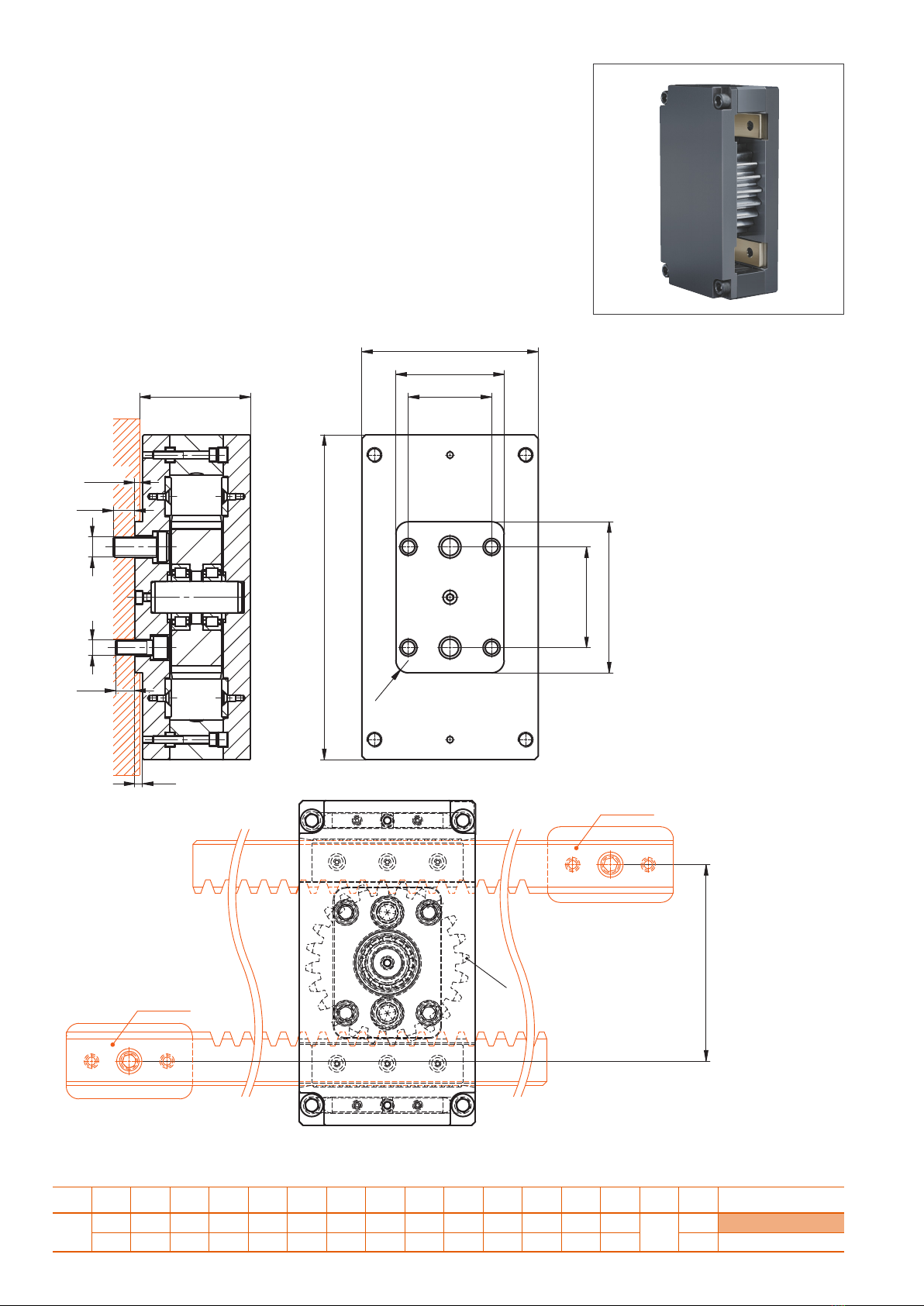
Z 1545/. . .
Getriebegehäuse
Gear housing
Boîte d’engrenages
r1 h2 h1 t1 a3 a2 a1 b2 b1 l4 l3 l2 l1 d2 d1 z1 m1 Nr. / No.
10 5,5 62 5 84 56 46 76 96 12 10 76 150 M8 M10 24 2,5 Z1545/24x 2,5
6,5 86,5 6 156 66 80 86 140 15 17 120 258 M12 M16 55
a2
a1
b2
g6
l2
g6
r1
b1
l1
a3
d1d2
t1
h1
l3
l4
Z1547
Z1547
h2
±0,01
z1
HASCO 3
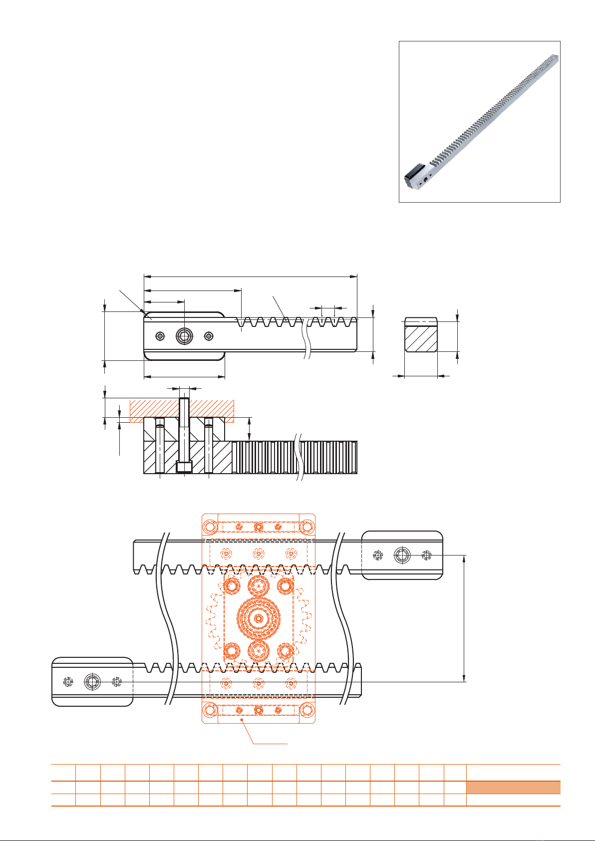
Z 1547/. . .
Zahnstangeneinheit
Rack unit
Unité à crémaillère
r1 p1 z1 h3 h2 h1 t1 a3 a2 a1 b2 l3 l2 d1 b1 l1 m1 Nr. / No.
6 7,85 90 25 22,6 27,5 5 84 30 95,5 40 13 60 M8 28 800 2,5 Z1547/ 28x800x2,5
10 15,7 69 37 29 42 6 156 50 120 60 18,6 100 M12 40 1200 5 40x1200x5
b2 g6
l2
g6
l1
h1
a2
r1
a1
p1
z1
h2
l3
d1
t1
b1
h9
h3
a3
Z1545
±0,01
4HASCO
1
2
3
4
5
6
7
8
9
10
11
12
13
14
15
16
18
17
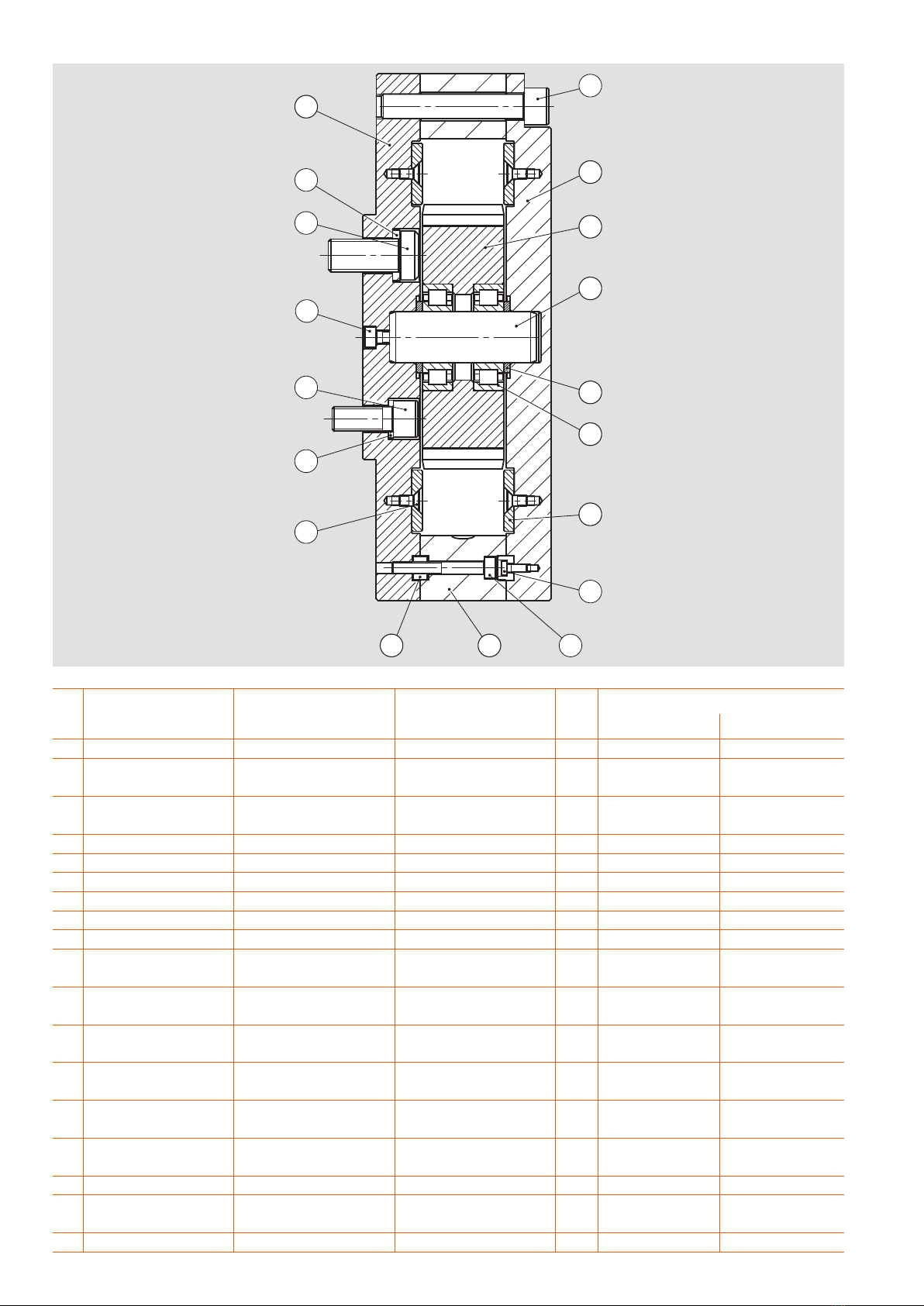
Pos. Benennung Description Désignation
Stck./
Qty. /
Pc.
Z1545/...
...24x 2,5 ...24x 5
1 Zahnrad Gear wheel Roue d’engrenage 1
2 Boden,
Getriebegehäuse
Bottom,
Gear housing
Plaque de fond,
boîte d’engrenages
1
3 Deckel,
Getriebegehäuse
Top cover,
Gear housing
Couvercle,
boîte d’engrenages
1
4 Führungsleiste Guide bar Barre de guidage 2
5 Gleitschiene Slide bar Rail coulissant 4
6 Achse Axle Axe 1
7 Distanzscheibe Spacer Entretoise 2
8 Passfeder Parallel key Ressort d’ajustage 8
9 Zylinderrollenlager Cylindrical roller bearing Roulement à cylindres 2 Z 1561/ 15 x 35 x 11 Z 1561/ 5 x 52 x 15
10 Zylinderkopfschraube Socket head cap screw Vis à tête cylindrique
à 6 pans creux
1Z31/5x10 Z31/6x16
11 Zylinderkopfschraube Socket head cap screw Vis à tête cylindrique
à 6 pans creux
2Z31/4x35 Z31/6x45
12 Zylinderkopfschraube Socket head cap screw Vis à tête cylindrique
à 6 pans creux
4Z31/8x25 Z31/12x30
13 Zylinderkopfschraube Socket head cap screw Vis à tête cylindrique
à 6 pans creux
4Z31/8x50 Z31/12x70
14 Zylinderkopfschraube Socket head cap screw Vis à tête cylindrique
à 6 pans creux
8Z31/4x8 Z31/4x10
15 Senkschraube Socket countersunk
head screw
Vis à tête fraisée
à 6 pans creux
12 Z33/5x16 Z33/5x10
16 Sperrkantring Locking edge washer Rondelle à bords d’arrêt 4 Z691/8x2 Z691/12x2,5
17 Zylinderkopfschraube Socket head cap screw Vis à tête cylindrique
réduite à 6 pans creux
2 DIN 7984
M10x25
DIN 7984
M16x35
18 Sperrkantring Locking edge washer Rondelle à bords d’arrêt 2 Z691/10x2,5 Z691/16x3,5
Z 1545 /. . .
Stückliste
Parts list
Liste des pièces
HASCO 5
Pos. Benennung Description Désignation
Stck./
Qty. /
Pc.
Z1545/...
...40x1200x 2,5 . . .40 x 1200 x 5
1 Zahnstange Gear rack Crémaillère 1
2 Zahnstangenhalterung Gear rack holder Support crémaillière 1
3 Zylinderstift Dowel pin Goupille cylindrique à
trou taraudé
2Z26/8x40 Z26/10x60
4 Zylinderkopfschraube Socket head cap screw Vis à tête cylindrique
à 6 pans creux
1Z31/8x55 Z31/12x75
5 Sperrkantring Locking edge washer Rondelle à bords d’arrêt 1 Z691/8x2 Z691/12x2,5
2
3
1
5 4
Z 1547/. . .
Stückliste
Parts list
Liste des pièces
6HASCO
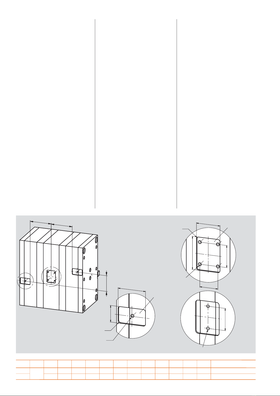
Einbaumaße Mounting dimensions Cotes de montage
Es sind immer zwei oder vier
Einheiten symmetrisch am Werkzeug
anzubringen.
Bild 1
Beide Zahnstangeneinheiten müssen
symmetrisch im Abstand zum Gehäuse
platziert werden.
Bild 2
Einbauraum für die Zahnstangen-
einheiten Z 1547/. . .
Die Gewindebohrung d2 ist mittig in der
Tasche zu platzieren.
Es ist zwingend erforderlich, dass die
Zahnstangenhalterung in Belastungs-
richtung von der Tasche umschlossen
ist.
Bild 3 und 3.1
Gestaltung des Einbauraumes für das
Getriebegehäuse Z 1545 /. . .
Je nach Plattenauswahl ist es möglich,
das Gehäuse mit vier Zylinderkopf-
schrauben zu befestigen.
Alternativ sind zwei Zylinderkopf-
schrauben vertikal im Abstand von
a1 mittig in der Tasche anzuordnen.
Es ist zwingend nötig, dass die Tasche
den gesamten Absatz (b2 x l2) des
Getriebegehäuses Z1545/... umgreift.
Dabei müssen die drei Taschentiefen
(für Z1545/... und Z1547/...) exakt auf
einer Ebene zueinander liegen.
Either two or four units must always be
mounted symmetrically on the mould.
Fig. 1
Both gear rack units must be mounted
symmetrically in terms of their distance
from the gear housing.
Fig. 2
Mounting space for gear rack units
Z 1547/. . .
The d2 threaded hole must be placed
centrally in the pocket.
It is essential for the gear rack holder
to be enclosed within the pocket in the
direction of loading.
Fig. 3 and 3.1
Configuring the mounting space for
the gear housing Z 1545 /. . .
Depending on the plate selected, the
housing can be fastened with four
M12 socket head cap screws.
Alternatively, two M16 socket head cap
screws can be centred in the pocket,
with a vertical spacing of a1.
It is essential for the pocket to enclose
the entire ledge (b2 x l2) of the Z1545/...
gear housing. The three pocket depths
(for Z1545/... and Z1547/...) must be
located on precisely the same plane
as each other.
Il convient de toujours installer deux ou
quatre unités de façon symétrique sur
l'outil.
Ill 1
Les deux unités à crémaillère doivent
être positionnées à distance de la boîte
de façon symétrique.
Ill 2
Espace de montage pour les unités
à crémaillère Z 1547/. . .
Le trou taraudé d2 doit être positionné
de façon centrée dans la poche.
Il est impérativement nécessaire que
le support à crémaillère soit entouré par
la poche dans la direction de la charge.
Ill 3 et 3.1
Conception de l'espace de montage
pour la boîte d'engrenages Z 1545 /. . .
Selon le choix des plaques, il est possi-
ble de fixer la boîte avec quatre vis à
tête cylindrique. À titre d'alternative, il
convient de disposer deux vis à tête
cylindrique verticalement à une distance
de a1, de façon centrée dans la poche.
Il est impérativement nécessaire que
la poche entoure l'intégralité de
l’épaulement de la boîte d’engrenages
Z1545/.... Ce faisant, les trois profon-
deurs de poche (pour Z1545/... et
Z1547/...) doivent être situées
exactement dans le même plan.
= =
a3
±0,05
b2
H7
l2
H7
r2
t2 +/-0,01
tief/deep/profond
d2
b1
H7
l1
H7
a1
±0,1
a2
±0,1
r1
d1
t1 +/-0,01
tief/deep/profond
a1
±0,100
d3
1
2
3
3.1
r2 r1 t2 t1 a3 a2 a1 b2 b1 l2 l1 d3 d2 d1 Nr. / No.
610 5584 56 46 40 76 60 76 M10 M8 M8 Z1545/24x 2,5
10 66156 66 80 60 86 100 120 M16 M12 M12 5
HASCO 7
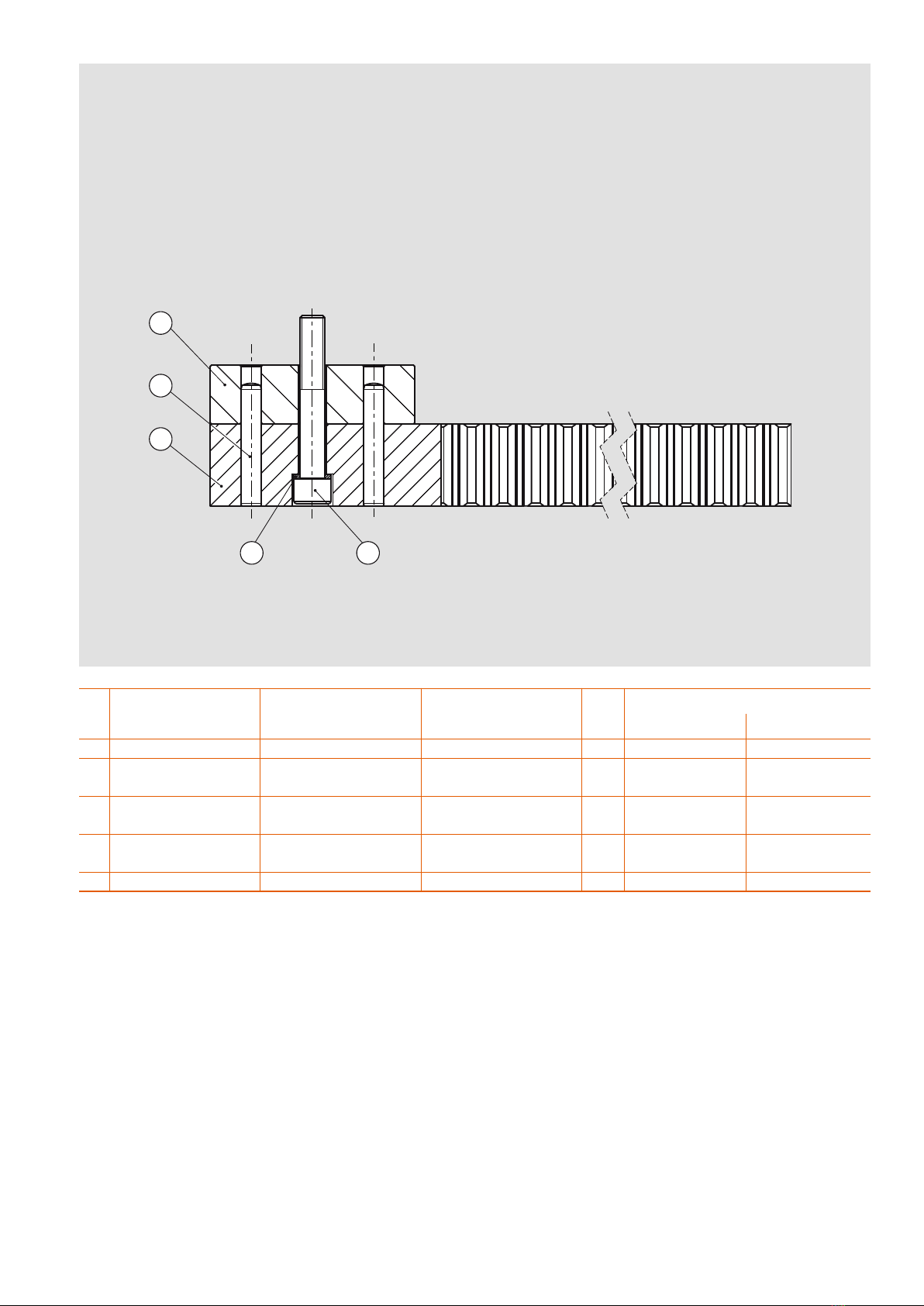
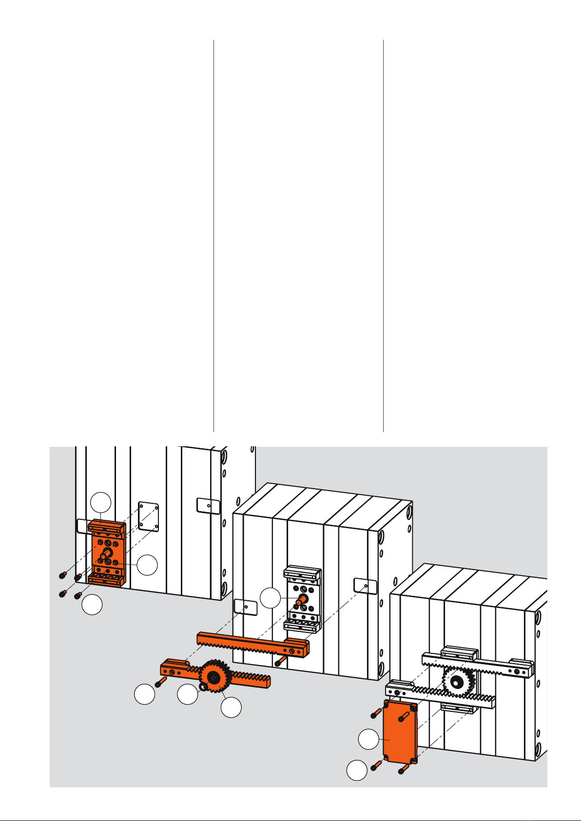
Montage Mounting Montage
Das Getriebegehäuse Z1545/... wird
bereits vormontiert geliefert.
Zunächst den Deckel Pos. durch das
Lösen der 4 Schrauben Pos. vom
restlichen Gehäuse trennen.
Das Zahnrad Pos. sowie die
Distanzscheibe Pos. aus dem
Getriebegehäuse entnehmen,
um Zugang zu den Befestigungs-
möglichkeiten zu erhalten.
Die Bodenplatte Pos. in die vorgefer-
tigte Tasche einsetzen und mit Hilfe der
Zylinderschrauben Pos. sowie den
Sperrkantringen Pos. am Mittelblock
des Werkzeuges befestigen.
Nach Befestigung des Getriebegehäu-
ses werden die Zahnstangeneinheiten in
die vorgefertigten Taschen eingesetzt
und mit den Zylinderkopfschrauben
Pos. befestigt.
Danach wird das Zahnrad Pos. auf
die Achse Pos. gesteckt.
Achtung:
Sowohl unterhalb als auch oberhalb
des Zahnrades Pos. eine Distanz-
scheibe Pos. montieren.
Den Deckel Pos. aufsetzen und mit
Hilfe der Zylinderschrauben Pos.
verschrauben.
The Z1545/... gear housing is supplied
pre-assembled.
First remove the top cover from the
rest of the housing by undoing the 4
screws .
Remove the gear wheel and the
spacer from the gear housing to gain
access to the attachment points.
Put the bottom plate in the prefabri-
cated pocket and fasten to the central
block of the mould with the socket head
cap screws and the locking edge
washers .
After the gear housing has been
attached, the rack units are positioned
into the prefabricated pockets and
fastened with the socket head cap
screws .
The gear wheel is then placed on the
axle .
Caution:
Insert a spacer both below and
above the gear wheel .
Replace the top cover and screw on
with the aid of the socket head cap
screw .
La boîte d'engrenages Z1545/... est
fournie déjà prémontée.
Dans un premier temps, séparer le
couvercle pos. du reste de la boîte
en desserrant les 4 vis pos. .
Retirer la roue d'engrenage pos.
et l'entretoise pos. de la boîte
d'engrenages afin d'obtenir un accès
aux possibilités de fixation.
Insérer la plaque de fond pos. dans
la poche préfabriquée et la fixer sur le
bloc central de l'outil à l'aide des vis à
tête cylindrique pos. et des rondelles
à bords d'arrêt pos. .
Après la fixation de la boîte d'engre-
nages, les unités à crémaillère sont
insérées dans les poches préfabriquées
et sont fixées avec les vis à tête
cylindrique pos. .
Ensuite, la roue d'engrenage pos. est
insérée sur l'axe pos. .
Attention:
Monter une entretoise pos. aussi
bien au-dessous qu'au-dessus de la
roue d'engrenage pos. .
Placer le couvercle pos. et le visser
à l'aide des vis à tête cylindrique
pos. .
2
12
16
1
74
6
3
13
© by HASCO Hasenclever GmbH+CoKG · Postfach 1720 · D-58467 Lüdenscheid · Tel. +49 (0)2351 957-0 · Fax +49 (0) 2351 957-237 · [email protected] · www.hasco.com 09 17 1 2,5 14
Technische Änderungen vorbehalten. Bitte überprüfen Sie stets sämtliche Angaben anhand unserer veröffentlichten Produktinformationen im Internet.
Subject to technical modifications. Please always check all the data against the product information we publish in the internet.
Sous réserve de modifications techniques. Veuillez toujours vérifier toutes les données au moyen de nos informations produits publiées sur Internet.
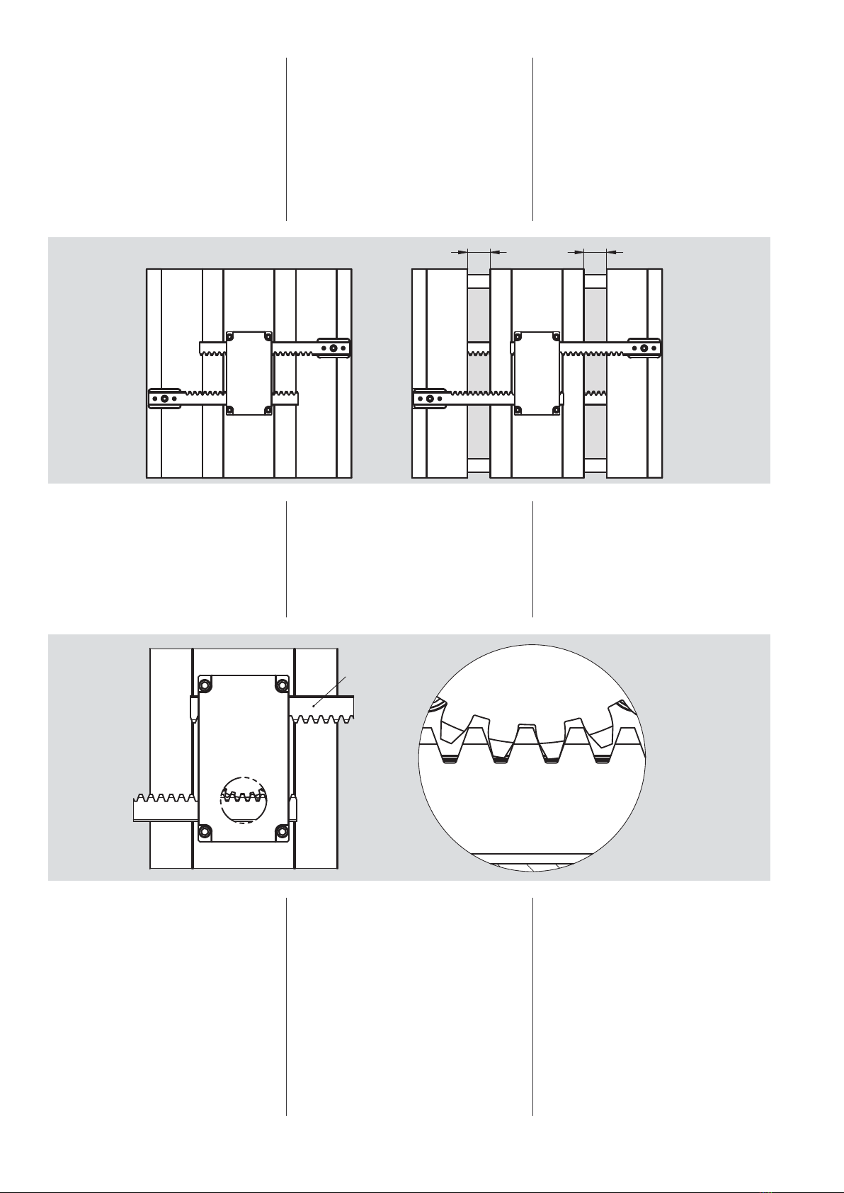
Funktion Function Fonction
Die Kombination aus Getriebegehäuse
Z1545/... und Zahnstangeneinheit
Z1547/... ermöglicht eine weitere
Trennebene im Werkzeug. Bei gleich-
bleibender Werkzeuggröße kann somit
die Fachzahl und der Produktionsaus-
stoß verdoppelt werden.
Bild 1
Bewegungsablauf beim Einsatz der
Etagenwerkzeugkomponenten
Z 1545 /. . . und Z 1547/. . .
Die einfache mechanische Übersetzung
öffnet synchron beide Trennebenen.
Bild 2
Das Zahnrad muss immer im Eingriff der
Zahnstangen Z1547/... sein.
Bitte beachten:
Die maximale Einsatztemperatur von
120°C darf nicht überschritten werden.
Maximale dynamische Belastung:
Z1545/ 24 x 2,5 = 80 Nm; 2,5 KN
24x5 = 480 Nm; 8 KN
Es ist vorzugsweise der Schmierstoff
Z260/... zu verwenden.
The combination of gear housing
Z1545/... and rack unit Z1547/...
permits an additional parting plane
in the mould. The number of cavities
and production output can thus be
doubled for the same mould size.
Fig. 1
Movement sequence when using
stack mould components
Z 1545 /. . . and Z 1547/. . .
The simple mechanical transmission
opens both parting planes synchro-
nously.
Fig. 2
The gear wheel must always be en-
gaged in the rack units Z1547/... .
Please note:
The maximum service temperature of
120°C must not be exceeded.
Maximum dynamic loading:
Z1545/ 24 x 2,5 = 80 Nm; 2,5 KN
24x5 = 480 Nm; 8 KN
Lubricant Z260/... should preferably
be used.
La combinaison de la boîte d'engrena-
ges Z1545/... et de l'unité à crémaillère
Z1547/... permet d'obtenir un niveau
de séparation supplémentaire dans
l'outil. Dans le cas d'un outil de taille
constante, le nombre d'empreintes
et le volume de production peuvent
ainsi être doublés.
Ill. 1
Série de mouvements lors de l'utilisa-
tion des composants d'outil à étages
Z 1545 /. . . et Z 1547/. . .
L'engrenage mécanique simple ouvre
les deux niveaux de séparation de
façon synchrone.
Ill. 2
La roue d'engrenage doit toujours être
engrenée dans les crémaillères
Z1547/... .
Attention:
La température maximale d'utilisation
de 120°C ne doit pas être dépassée.
Charge dynamique maximale:
Z1545/ 24 x 2,5 = 80 Nm; 2,5 KN
24x5 = 480 Nm; 8 KN
Il convient d'utiliser, de préférence,
le lubrifiant Z260/... .
H1 H1
HASCO
Z1545/24x5
HASCO
Z1545/24x5
Z1547/...
HASCO
Z1545/24x5
1
2
This manual suits for next models
1
Table of contents
Other Hasco Industrial Equipment manuals


