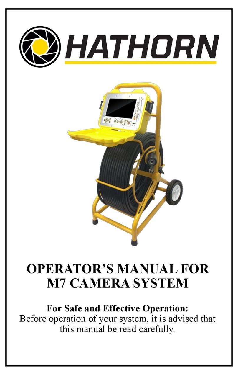
Hathorn CL 2150 User manual

1
OPERATOR’S MANUAL FOR
HATHORN CL 2150 SONDE
LOCATOR
For Safe and Effective Operation:
Before operation of your system, it is advised that
this manual be read carefully.

2
CONTENTS
PEAK MODE
PAGE 10 SPECIFICATIONS
PAGE 11 SERVICE & WARRANTY

3
INTRODUCTION
The CL 2150 Locator is specially designed to detect camera systems
and sondes and the unit is capable of detecting buried power cables,
CATV cables, gas and water pipes, sewer lines, telephone cables, fi-
ber optic cables with sheath.
The Transmitter/Sonde emits a signal. The Receiver detects the sig-
nal. You can locate the relative position of the buried pipe of camera
by following the tracing signal.
For sonde locating & camera head locating a signal is generated by
the sonde or camera head and the receiver detects the signal giving
the user proximity cues to determine its location.
Unpack your new CL 2150 Camera and Sonde Locator. Make sure
there is no shipping damage and all the parts are included.
Locate the battery compartment on the back of the “head” of the Re-
ceiver. Open the compartment using a Phillips screwdriver. Install
the six Duracell® “C” batteries as marked. NOTE: For longer bat-
tery life and reliable operation under adverse conditions, use only Du-
racell® alkaline batteries
DISCLAIMER OF LIABILITY
HATHORN CORPORATION SHALL NOT BE LIABLE TO DIS-
TRIBUTOR, RESELLER, OR ANY OTHER PERSON FOR AN IN-
CIDENTAL, INDIRECT, SPECIAL, EXEMPLARY OR CONSE-
QUENTIAL DAMAGES, OR INJURY OF ANY TYPE WHATSO-
EVER, AND CAUSED DIRECTLY BY PRODUCTS SOLD OR
SUPPLIED BY HATHORN CORPORATION.

4
ABSOLUTE SIGNAL STRENGTH
The CL 2150 Locator receiver provides the operator with a direct
measurement of the receiver’s signal strength. The measurement is
displayed with three numerical digits (ex: 485) located at the bottom
of the LCD display. The measurement range is from -100 to 999 indi-
cating a very week signal (-050) to a very strong signal (999) Abso-
lute Signal Strength is independent of the GAIN setting or meter
reading. It gives the operator information about the actual amount of
signal being radiated from the conductor and received by the receiver.
Measuring Absolute Signal Strength at any time is done by reading
the number at the top of the LCD display. The Absolute Signal
Strength is displayed even when the meter reading is off scale (too
high or too low).
GAIN CHANGE INDICATION
The GAIN up and down buttons are used to increase and decrease the
gain in small amounts. If the meter reading is very low, pressing the
GAIN UP button will center the meter reading to mid-scale. Like-
wise, if the meter reading is very high, pressing the GAIN DOWN
button will center the meter reading to mid-scale.
DIGITAL DEPTH ESTIMATE
The CL 2150 Locator estimates the depth automatically. The depth is
displayed at the top of the LCD display in feet or inches. Digital
depth is useful in quickly determining the depth of the conductor dur-
ing path locating.
To change the Depth Measurement from SONDE to LINE, hold the
Frequency Key for three seconds and the next setting will appear.
Caution must be exercised when using the digital depth feature, as
tilted magnetic fields and adjacent conductors can significantly influ-
ence this measurement. The operator should periodically check for
adjacent conductors and tilted magnetic fields when taking push but-
ton depth readings.
LOW BATTERY
The CL 2150 Locator will indicate low battery condition by display-
ing the low battery icon at the bottom right of the LCD screen.

5
CL 2150 RECEIVER CONTROLS AND INDICATOR
ON/OFF BUTTON
Press the ON/OFF button
to turn the receiver on.
Note: Unit will automati-
cally shut off if no keys
are pressed within a 10-
minute period.
FREQUENCY &
MODE BUTTON
The configuration of the
unit (See page 3), will
determine the functional-
ity of the Frequency & Mode button. If configured to 512, the unit
will only operate in 512Hz Sonde locating mode and the Frequency
Button will be functionless.
If configured to U3, the unit will only offer multiple sonde locating
frequencies. Press the frequency button to toggle through available
frequencies. Press and hold the frequency button for 3 seconds to tog-
gle between line mode and sonde locating modes.
SONDE MODE: 512HZ, 640HZ, 8KHZ, 33KHZ.
The unit may be configured to the following line mode frequencies:
passive 50hz & 60hz, passive rF, 512hz, 640hz, 8khz, 9khz, 33khz,
65khz, 82khz, 200khz, 478khz
GAIN BUTTON (UP OR DOWN)
Used to adjust the gain level for the receiver. When the gain button is
pressed, The receiver will adjust the gain up or down. If the bar graph
is off scale, pressing the GAIN up or down key will automatically
adjust to 85% on the scale display.
NOTE:
WHILE HOLDING “POWER” BUTTON, PRESS THE
“DEPTH” BUTTON TO NAVIGATE THROUGH FRE-
QUENCY OPTIONS. CHOOSE “512 Hz” FOR
HATHORN SYSTEMS.

6
LOCATING A SONDE OR CAMERA HEAD USING THE CL
2150
Before you begin, you must
choose a Sonde that will
match the same frequency as
the receiver. You will need a
Sonde with a frequency of
512HZ, 640HZ, 8KHZ, or
33KHZto use with the CL
2150 Locator Receiver.
The key to Sonde locating
success is practice and patience. Before going out on your first locate, it
is a good idea to take your receiver and Sonde out and try locating the
Sonde and calculating the depth.
Attaching a Push Device
Attaching a push rod to the
Sonde can be accomplished
by using the coupling on the
end of the Sonde. A spring
coupling is recommended to
allow the sonde to move eas-
ier. Or, if you need to attach
the Sonde to a sewer auger, it
is recommended you use
duct tape and apply as the
shown in the figure below. If
taping the Sonde on a metal
pushing device, it is recom-
mended to place the battery
side of the Sonde closest to
the device. This will allow
for the best performance.
Wrap the snake for approxi-
mately 1 foot in the location
where the Sonde is going to
be attached. Also attaching the Sonde 18 inches behind the cutting head
is recommended. First, wrap the Sonde in the duct tape and then attach
the Sonde to the snake using the duct tape.

7
LOCATING A SONDE
Hold the Receiver antenna direct-
ly above and in line with the
Sonde, as shown below. The Re-
ceiver sensitivity needs to be ad-
justed for a meter reading indica-
tion between 60% to 80%.
The radiation pattern of the Sonde
is shown below. The PEAK sig-
nal is when the Receiver is held
directly over the Sonde with the
antenna in line with the Sonde.
Both Ghost signals can be located
behind and in front of the Sonde. By locating the ghost signals, the
user is confirming the accuracy of the locate.
Start by following the suspected path of the pipe and use the CL
2150 Locator to locate the SONDE. Stop locating when the PEAK
reading is found. Then rotate the RECEIVER as shown in the fig-
ure below. When pivoting the RECEIVER, do not change the verti-
cal position. The RECEIVER will indicate a PEAK when the RE-
CEIVER antenna is in line with the SONDE.
Now move the RECEIVER side to side (across the path of the pipe)
as shown below. When the PEAK is found, the RECEIVER is di-
rectly over the SONDE. Mark this location. Next, check for ghost
signals in front and in back of the SONDE to confirm the location.

8
DEPTH MEASUREMENT OF CAMERA HEAD OR SONDE
Once the SONDE has been located, the depth can then be found. Refer to
the figure below for a reference. Start by moving the RECEIVER along
the path behind the SONDE with the antenna in line with the SONDE and
find a NULL between the PEAK ghost signals. Mark this point (A). Then
move the RECEIVER along the path in
front of the SONDE and find another
NULL. Mark this point (B). Next,
measure the distance between these two
points. The depth of the pipe is 0.7
times the distance between the two
points.
PUSH BUTTON DEPTH
The CL 2150 Locator is specially de-
signed to measure the SONDE depth
digitally.
To use this feature, the RECEIVER must be placed in the position shown
in the diagram above. The RECEIVER antenna must be in line with the
SONDE.
The RECEIVER must also be in the SONDE mode (holding the Depth for
a long press of three seconds switches depth mode). Locate the SONDE
as described previously.
When the SONDE has been located, press the DEPTH button. The LCD
display will indicate dEP, SON and display the depth of the SONDE in
feet or meters.
The only way to be sure of the depth of a utility is to expose the utili-
ty. At any time, the depth readout may be inaccurate as it may be af-
fected by metallic objects in the ground.
Caution must be exercised when using the push button depth feature, as
tilted magnetic fields and adjacent conductors can significantly influence
this measurement. The operator should periodically check for adjacent
conductors and tilted magnetic fields when taking push button depth read-
ings.

9
LOCATING A CABLE OR PIPE PATH
Using either a Line Transmitter or Passive locate mode a user
may be able to locate a buried utility. Hold the RECEIVER so
that you can see the LCD bar graph and controls easily. Make
sure the RECEIVER and the TRANSMITTER FREQUENCY are
both set the same, 512Hz.
PEAK MODE LOCATING
Keep the RECEIVER in a vertical position. Move the RECEIVER
left to right across the path. When the RECEIVER is directly
above the cable or pipe, rotate the RECEIVER for a maximum sig-
nal. As you move the RECEIVER away from the cable path, the
meter reading (and audio frequency response) will drop off.
If you rotate the RECEIVER while over the cable, a sharp NULL
will identify the cables’ direction. It is aligned with the flat side
of the RECEIVER.

10
CL 2150 LOCATOR SPECIFICATIONS

11
FACTORY SERVICE
If your CL 2150 Locator is not working properly,
call Hathorn Corporation Support at 905-604-7040 for assistance. If
the locator is in need of repair, Hathorn Corporation will provide
instructions and a Return Merchandise Authorization (RMA) for
returning your locator to the service center. The instrument will be
repaired and shipped back with an invoice or you will be advised if
the instrument is un-repairable.
SEND UNIT PREPAID TO:
Hathorn Corporation
ATTN. Repair (Include RMA#)
255 Shields Ct. Unit C. DOCK 2
Markham, ON Canada L3R8V2
+1-905-604-7040
WARRANTY
THIS INSTRUMENT IS UNDER WARRANTY FOR ONE YEAR
FROM THE DATE OF DELIVERY AGAINST DEFECTS IN MA-
TERIAL AND WORKMANSHIP (Excluding Batteries). WE
WILL REPAIR OR REPLACE PRODUCTS THAT PROVE TO
BE DEFECTIVE DURING WARRANTY PERIOD.
THIS WARRANTY IS VOID IF, AFTER HAVING RECEIVED
THE INSTRUMENT IN GOOD CONDITION, IT IS SUBJECTED
TO ABUSE, UNAUTHORIZED ALTERATIONS OR CASUAL
REPAIR.
NO OTHER WARRANTY IS EXPRESSED OR IMPLIED. THE
WARRANTY DESCRIBED IN THIS PARAGRAPH SHALL BE
IN LIEU OF ANY OTHER WARRANTY, INCLUDING BUT
NOT LIMITED TO, ANY IMPLIED WARRANTY OR MER-
CHANTABILITY OR FITNESS FOR A PARTICULAR PUR-
POSE. WE ARE NOT LIABLE FOR CONSEQUENTIAL DAM-
AGES.

12
Hathorn Canada
255 Shields Court, Unit C
Markham, Ontario, Canada
L3R 8V2
+1 (866) HATHORN
Hathorn USA
739 North Wilson Road
Columbus, Ohio, USA
43204
+1 (855) 863-9226
Table of contents
Other Hathorn Analytical Instrument manuals

