1. Application and functionality
of HEL11C
The controller is designed for gate drives with 230Vac
motors. A perfect choice for continuous operation, the
controller can be used in community car parks, private
homes and corporate compounds. Applied Microchip
rolling code technology prevents from not authorized
entrance. The controller cooperates with monostable
pushbutton with Step-By-Step functionality,
(OPEN-STOP-CLOSE-STOP) The control unit perform
following operations: Autoclose, Open only and Automatic
wicket The are two available main versions. First one
with encoder input, and second one without it.
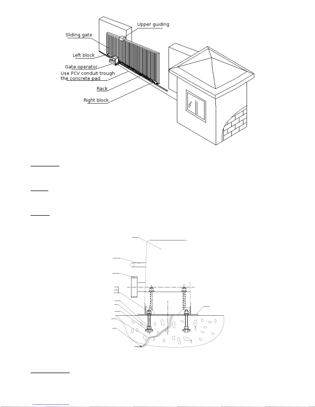
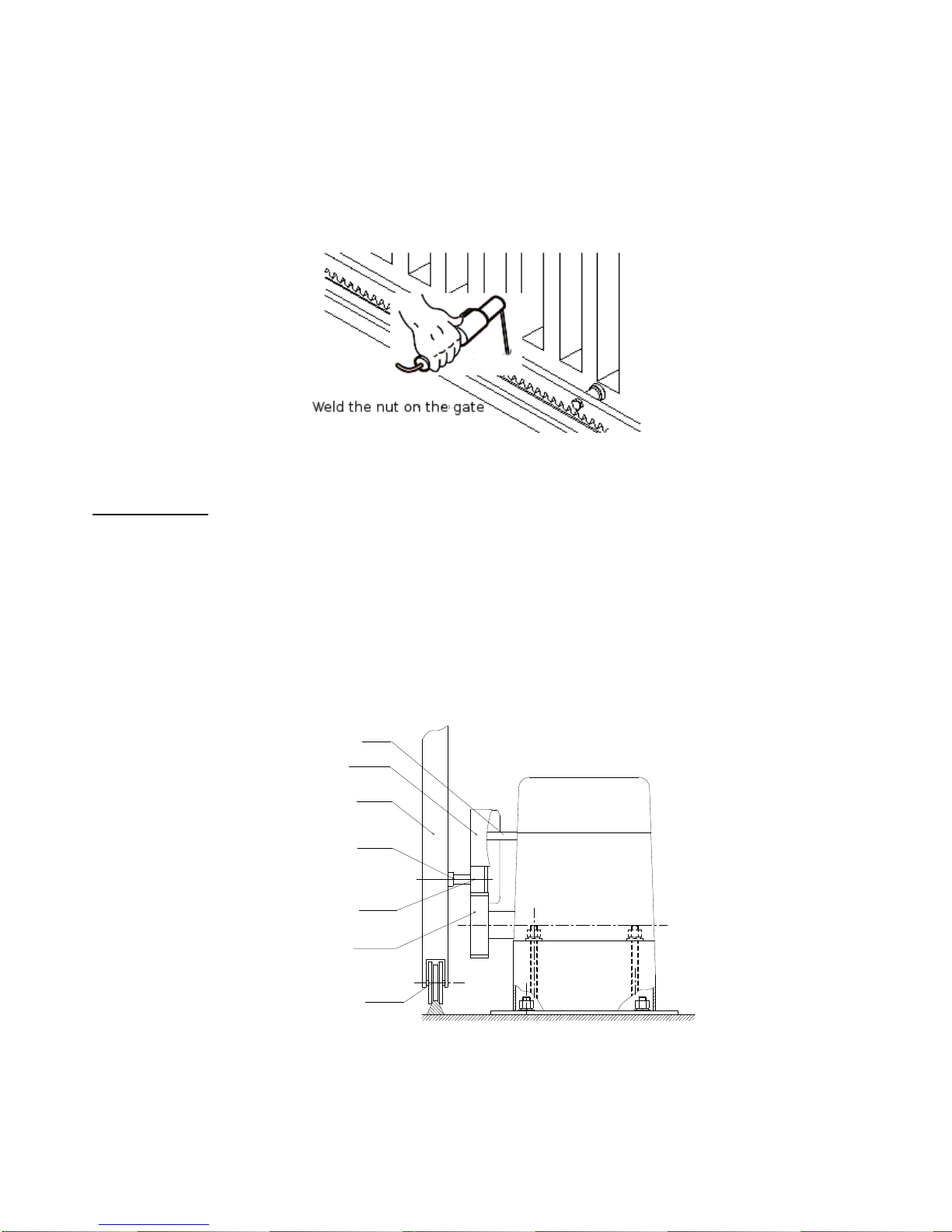
2. Installation
Install the controller into drive. All dimensions are in the
Picture 1. After correct installation continue with
electrical connection.
The manufacturer will not be liable for losses and
disruption in work resulting from non-observance of this
installation, operation manual and applicable regulations.
2.1 Limit switches connection
At first connect limit switches to the controller inputs
marked as (16,17,18). Check the gate condition: the gate
should not swing too much, it should move easily and
smoothly between limit positions. If necessary adjust
placements of magnetic parts.
16 (OL) —open limit,
17 (CL) —close limit,
18 (COM) —common, (white wire)
The controller cooperates with Normally Open or Normally
Closed limit switches. To change type of limit switches
solder the ZS jumper on PCB. With soldered jumper
version marked as NO cooperates with NC type switches
and version marked as NC cooperates with NO switches.
If you have cotroller without encoder input - skip point 2.2.
2.2 Encoder connection
Motor encoder must be connected to the inputs marked as
"ENCODER" (Pic.2)(21,22,23,24).
Connect the encoder wires to the plug according to wiring
diagram description. The controller uses encoder impulses
to calculate applicable force. Uncorrect connection may
cause unproper operation and hazardous situation to healt
and life.
21 - ─ ─ - encoder signal
22 - + + + - GND
23 - ─x─ - GND
24 - - supply (+5V)
Enkoder parameters: 717 impulses per second (speed
1450rpm)
2.3 Photocell connection
Photocell barrier is a necessary safety element which
must be connected to the controller. It increases safety
and prevents a gate wing from hitting a car, a person or an
object which are within the photocells’ range. In the
controller without encoder input it is necessary to connect
gate optical curtain or other safety elements preventing
from accidentally crush. It should be in series with
photocell.
12 –Photocell supply +24Vdc
13 –Photocell supply GND
13-14 –Normally Closed contact
Output (+24V) current cannot exceed < 450mA. Make
sure power consumption of all connected accesorries.
Example of photocell connection is shown on the wiring
diagram.