HAWE Hydraulik INKA 1 User manual

Compact hydraulic power pack type INKA 1
Assembly instructions
(Translation of the original instructions)
B 8132-1
02-2023-1.3en
Oil immersed compact hydraulic power pack with built-in
electric motor (AC or 3-phase version) and single-circuit
pump.
For short period operation S2 and periodic intermittent
operation S3.

© by HAWE Hydraulik SE.
The reproduction and distribution of this document, as well as the use and communication of its contents to others without explicit
authorization, is prohibited.
Offenders will be held liable for the payment of damages.
All rights reserved in the event of patent or utility model applications.
Brand names, product names and trademarks are not specifically indicated. In particular with regard to registered and protected names
and trademarks, usage is subject to legal provisions.
HAWE Hydraulik respects these legal provisions in all cases.
HAWE Hydraulik cannot provide individual guarantees that the stated circuits or procedures (including in part) are not subject to the
intellectual property rights of third parties.
Printing date / document generated on: 2023-05-11
2/55 B 8132-1 - 02-2023 - 1.3 en HAWE Hydraulik SE

Table of Contents
1 About these instructions.................................................................................................................................. 5
1.1 Target audience................................................................................................................................................. 5
1.2 Safety instructions and symbols...........................................................................................................................5
1.3 Applicable documents......................................................................................................................................... 7
2 For your safety................................................................................................................................................ 8
2.1 Intended use.....................................................................................................................................................8
2.2 Residual risks.................................................................................................................................................... 9
2.3 Duties of the operator........................................................................................................................................9
2.4 Qualification of the personnel............................................................................................................................10
2.5 Personal protective equipment........................................................................................................................... 10
3 About this product......................................................................................................................................... 11
3.1 Structure......................................................................................................................................................... 11
3.2 Control............................................................................................................................................................12
3.3 Sensors........................................................................................................................................................... 12
3.3.1 Parametrisation................................................................................................................................................13
3.3.2 Values measured by the sensors......................................................................................................................... 14
4 Transport and storage..................................................................................................................................... 16
4.1 Transport equipment......................................................................................................................................... 16
4.2 Scope of delivery............................................................................................................................................. 16
4.3 Checking the delivery........................................................................................................................................17
4.4 Storage........................................................................................................................................................... 17
5 Assembly and installation...............................................................................................................................18
5.1 Mechanical connection......................................................................................................................................18
5.2 Hydraulic connection........................................................................................................................................ 20
5.3 Electrical connection........................................................................................................................................ 21
5.3.1 Connecting the motor.......................................................................................................................................22
5.3.2 Connecting an external fan............................................................................................................................... 23
5.3.3 Connecting to parametrisation interface..............................................................................................................24
5.3.4 Connecting the sensors.....................................................................................................................................25
5.3.5 Connecting the operating capacitor.................................................................................................................... 26
6 Start-up......................................................................................................................................................... 27
6.1 Switching the hydraulic system on/off................................................................................................................ 29
7 Maintenance...................................................................................................................................................30
7.1 Maintenance plan............................................................................................................................................. 31
7.2 Service............................................................................................................................................................31
7.2.1 Bleed the hydraulic power pack......................................................................................................................... 31
7.2.2 Check the hydraulic uid level........................................................................................................................... 32
7.2.3 Replacing the hydraulic uid............................................................................................................................. 33
7.2.4 Checking and replacing the pressure and return line lters.................................................................................... 33
7.2.5 Checking the valves..........................................................................................................................................34
7.2.6 Checking accumulator systems........................................................................................................................... 34
7.2.7 Checking the motor.......................................................................................................................................... 34
7.2.8 Replacing an external fan..................................................................................................................................35
8 Disassembly and disposal................................................................................................................................37
9 Troubleshooting..............................................................................................................................................38
HAWE Hydraulik SE B 8132-1 - 02-2023 - 1.3 en 3/55

10 Appendix........................................................................................................................................................40
10.1 Technical data..................................................................................................................................................40
10.1.1 General data....................................................................................................................................................40
10.1.2 Pressure and volumetric ow............................................................................................................................. 41
10.1.3 Weight............................................................................................................................................................ 41
10.1.4 Tank size.........................................................................................................................................................42
10.1.5 Characteristic lines........................................................................................................................................... 42
10.1.5.1 Build-up of heat.............................................................................................................................................. 42
10.1.5.2 Running noise..................................................................................................................................................44
10.1.6 Electrical data..................................................................................................................................................45
10.1.7 Motor data...................................................................................................................................................... 47
10.1.7.1 Current consumption characteristic lines............................................................................................................. 48
10.1.8 Additional options............................................................................................................................................49
10.1.8.1 Additional option: sensor system....................................................................................................................... 49
10.1.8.2 External fan.....................................................................................................................................................49
10.1.9 Sensor characteristics....................................................................................................................................... 49
10.2 Documents.......................................................................................................................................................51
10.2.1 Declaration of incorporation.............................................................................................................................. 51
10.2.2 Declaration of conformity..................................................................................................................................53
4/55 B 8132-1 - 02-2023 - 1.3 en HAWE Hydraulik SE

1About these instructions
This manual is part of the product and describes the safe and proper use in all operating phases.
All photos and drawings in this manual show an available product variant. For precise details concerning
the variant you have purchased, please refer to the type plate attached to the product.
Read instructions before use.
Make the manual accessible to operating and maintenance personnel at all times.
Keep this manual for the lifetime of the product.
Only pass on the product to third parties together with this manual.
1.1 Target audience
The target audience of this manual is trained and qualied personnel who are familiar with the installa-
tion, operation and maintenance of machines.
The manual provides relevant information for the machine manufacturer and machine operator as well as
for training courses.
You can request further information on the product at: HAWE Hydraulik SE, Einsteinring 17, 85609
Aschheim/Munich, Germany.
1.2 Safety instructions and symbols
Safety indication In these instructions, the following warning and safety notes are used:
Symbol Meaning
Draws your attention to a hazardous situation that can lead directly to
serious injury or death if not avoided.
Draws your attention to a hazardous situation that can indirectly lead to
serious injury or death if not avoided.
Draws your attention to a hazardous situation that can indirectly lead to
light to moderate injury if not avoided.
Notice to prevent environmental and material damage.
Information to ensure the correct use of the product.
HAWE Hydraulik SE B 8132-1 - 02-2023 - 1.3 en 5/55

Safety symbols General safety symbol
Draws your attention to additional safety information.
Slipping hazard Dragging hazard from
moving parts
Harmful substances Tripping and falling
hazard
Fire accelerants Falling loads
Burn hazard Crushing hazard
Electrical voltage Suspended loads
No access to persons
with pacemakers and
defibrillators
Mandatory signs Protective equipment
Safety boots
Wear appropriate safety boots to protect your feet against mechanical
hazards.
Work gloves
Wear suitable work gloves to protect your hands against chemical and
mechanical hazards.
Safety goggles
Wear safety goggles to protect your eyes against chemical and mechanical
hazards.
Protective clothing
Wear tted clothing without protruding parts.
Follow the safety data sheet of the hydraulic uid.
6/55 B 8132-1 - 02-2023 - 1.3 en HAWE Hydraulik SE

1.3 Applicable documents
Documents
D 5488/1 Oil recommendations
D 8132-1 Data sheet for compact hydraulic power pack type INKA 1
B 5488 General operating manual for the assembly, initial operation and
maintenance of hydraulic components and systems
"Declaration of incorporation (EU)"Declaration of incorporation
"Declaration of incorporation (UK)"
"Declaration of conformity (EU)"Declaration of conformity
"Declaration of conformity (UK)"
HAWE Hydraulik SE B 8132-1 - 02-2023 - 1.3 en 7/55

2For your safety
The product is built according to the state of the art and recognized safety regulations.
Nevertheless, there is a risk of personal injury and damage to property if this chapter and the safety
instructions in this manual are not observed.
2.1 Intended use
■The product is a technical work tool and intended for commercial and industrial use only.
■The product may only be operated in accordance with the technical data, operating conditions and
performance limits specied in this manual.
■Only use original accessories and original spare parts approved by the manufacturer.
■This product is used for controlling machine tools, hydraulic tools, handling systems, presses and
production machinery.
■The product must be used indoors.
■Do not operate electronics near devices that generate powerful magnetic elds or near electrical
conductors that carry high currents (> 30A/m).
■All components must be suitable for the operating conditions when using an assembly.
■Stationary use
Partly completed machinery
The product is a partly completed machine according to the EC Machinery Directive 2006/42/EC and
is intended exclusively for installation in a machine or system. The product is controlled via the
manufacturer's machine / plant control.
Comply with the manufacturer’s operating instructions of the higher-level machine or system.
Unintended use WARNING
Hazard from unintended use of the product
Any use of the product that goes beyond the intended use and/or varies from the intended use of the
product has the potential of leading to hazardous situations.
Only use the product for the stipulated purposes.
■Use in other operating modes than specied in the intended use
■Using the product beyond the specied performance limits
8/55 B 8132-1 - 02-2023 - 1.3 en HAWE Hydraulik SE

2.2 Residual risks
When handling hydraulic uid, comply with the safety data sheet of the uid's manufacturer.
DANGER
Risk to life due to explosive combustion
Hydraulic uid, and its associated mists and vapors, is a re accelerant. Contact with ignition sources
will lead to explosive combustion. Risk of serious injury or death.
Avoid re, open ames, and smoking anywhere near the product.
Immediately dispose of any ammable materials moistened with hydraulic uid as hazardous waste.
Do not use any ammable or corrosive cleaning agents.
WARNING
Electrical and magnetic elds
Electrical and magnetic elds impair the functionality of cardiac pacemakers and implanted defibrilla-
tors.
People with pacemakers or implanted defibrillators must maintain a sufcient distance from
magnets.
Advise people with pacemakers or implanted defibrillators against approaching magnets.
Cordon off the area around the drive system and afx suitable warning signs to the barriers.
WARNING
Risk of injury through crushing or cutting
Body parts might get trapped or severed between the machine frame and hydraulic system in the event
of careless transport, installation and de-installation.
Never reach between the hydraulic system and the machine frame.
Ensure other people cannot enter the hazardous area.
Wear gloves and appropriate footwear.
2.3 Duties of the operator
Observe and comply with regulations:
The product must not be commissioned until the complete higher-level machine or system complies
with the provisions, safety regulations and standards relevant in that country for the application.
Observe and apply regulations for accident prevention and environmental protection.
Assess and document any new dangers in the complete system’s manual.
Operate product safely:
Despite safety devices, the product still poses residual risks. Observe the safety instructions in this
manual to reduce health hazards and avoid dangerous situations.
The operating company must ensure the operating conditions (see the technical data) are within the
limits for use of the product.
Keep all instructions/signs on the product in legible condition and observe them.
HAWE Hydraulik SE B 8132-1 - 02-2023 - 1.3 en 9/55

Instruct personnel:
Regularly train personnel in all points of these instructions and ensure they are observed.
Ensure the terms of the industrial safety and operating instructions are observed.
Only use qualied personnel. Due to their training and experience, qualied personnel must be able to
recognize risks and avoid possible hazards.
2.4 Qualification of the personnel
The activities described in these instructions require basic knowledge of mechanics, hydraulics and
electrics.
For the transport and handling of heavy loads, additional knowledge in handling hoists and slings is
required.
The activities may only be carried out by an appropriate specialist or an instructed person under the
supervision of a specialist.
Activities other than those described in these instructions may only be performed by HAWE or
authorized specialist companies.
The personnel must have read and understood these instructions.
Trained personnel Personnel instructed comprehensively, by skilled staff on behalf of the owner, in how to perform their
appointed tasks and in how to use the product safely.
Specialist personnel Due to their technical training, knowledge and experience, specialists are able to assess and carry out the
assigned work and can independently recognize possible dangers.
Qualied electrician A person with appropriate professional training, knowledge and experience, so that he/she can recognize
and avoid dangers that can be caused by electricity.
Auditor Persons of a technical inspection body who are authorized to perform testing and monitoring tasks for
pressure equipment and electrical systems.
2.5 Personal protective equipment
Personal protective equipment (PPE) is designed to prevent and reduce hazards.
In the instructions, safety instructions with mandatory symbols indicate the wearing of special
protective equipment for special activities.
The supply of PPE, and instruction in its proper use, is carried out by the operator.
10/55 B 8132-1 - 02-2023 - 1.3 en HAWE Hydraulik SE

3About this product
3.1 Structure
The compact hydraulic power pack type INKA consists of the tank, the integrated motor and the radial
piston pump or gear pump directly attached to the motor shaft. The directly mounted electronic
communication box with integrated real-time operating system allows the operating state to be recorded
and visualised. The measured values of the integrated multi-sensor (including the motor speed) can be
passed on to the higher-level machine controls via standardised interfaces and processed there.
The consistently modular design of the type INKA means that different usage volumes and delivery ows
can be realised quickly and easily from the modular system. Compatible, ready-for-connection, complete
solutions can be assembled easily using a wide range of connection blocks and the valve banks that can
be combined with them.
It is designed in horizontal or vertical versions and supplies ow rate and pressure according to the
technical data. Tank size as well as pump and motor types can be varied.
1G1/2 ller port (hydraulic uid) and
breather lter
2Type plate
3Tank with:
■Pump
■Motor
■Power Unit Sensor (optional)
■External fan (optional)
4Connection block (optional), acc. to order
coding (D 8132-1) with:
■Free ports for direct piping connection (P,
R)
■Pressure or return line lter
■Valves
5Hydraulic uid drain G 1/2
6Communication box for:
■Motor connection
■Sensors and visualisation (optional)
■External fan connection, if present
Connection block
(optional)
Depending on the version, the connection block features:
■Free ports for direct piping connection
■Valve bank connection
■Pressure or return line lter
■Valves (accumulator charging valve, idle circulation valve, two-stage valve, throttle valve)
External fan (optional) The external fan is mounted on the side on the intermediate ange.
External fan start can be programmed for an oil temperature between 40°C and 70°C (any 10°C
increment selectable). Programmed switching hysteresis is 10°C.
HAWE Hydraulik SE B 8132-1 - 02-2023 - 1.3 en 11/55

External fan switches off again when oil temperature reaches 30°C. Switch-off temperature should lie
above the maximum expected ambient temperature. The external fan will switch off when oil tempera-
ture lies below the external fan’s switch-on temperature for 30 minutes but switch-off temperature is not
reached within this time.
3.2 Control
All of the necessary safety equipment, safety functions and the safety controller should be provided
by the machine manufacturer.
■The motor’s duty cycle should be monitored by the device control. An increase in the duty cycle is an
indicator of abnormal internal leakage.
The following must be integrated in the machine controls:
■The technical data specifications in the data sheets must be complied with.
3.3 Sensors
The Power Unit Sensor tracks a variety of parameters and supplies their values, together with a broad
range of calculated values, to the user, a superordinate control system or other peripherals.
The following measured values are tracked:
■Hydraulic uid level (capacitive)
■Hydraulic uid temperature
■Speed of the drive unit incorporated in the hydraulic power pack
Automatically calculated values:
■Hydraulic power pack’s cycle count
■Motor utilisation
■Theoretical ow rate
■Sensor operating time spread across several temperature ranges
■Hydraulic power pack’s operating time spread across several temperature ranges
■Hydraulic power pack’s operating time spread across several motor load ranges
Visualisation is by means of LEDs on the communication box’s cover or through the IO-Link communica-
tions system.
Variant sensors Two variants of the Power Unit Sensor are available:
■IO-Link
■Switch output
Function Sensors with IO-Link Sensors with switch output
IO-Link ✓-
3 switch outputs - ✓
Visualisation ✓ ✓
External fan control ✓ ✓
Parametrisation interface Parametrisation via IO-Link ✓
12/55 B 8132-1 - 02-2023 - 1.3 en HAWE Hydraulik SE

Sensors with IO-Link
interface
IO-Link vendor ID (HAWE) 1503 (0x5DF)
IO-Link website io-link.com
IODD Finder ioddfinder.io-link.com
Sensors with switch output Switch outputs 1, 2, and 3 can be congured independently of each other. Parametrisation handled at
factory (D 8132-1, section 2.1).
3.3.1 Parametrisation
Parametrisation interface NOTICE
To facilitate sensor parametrisation, some variants feature a parametrisation interface in the communi-
cation box.
The programming cable with USB connector can be connected to the parametrisation interface.
Port: see "Connecting to parametrisation interface", page 24
Switch outputs Behaviour of the switch outputs can be congured as desired. The following factors can be dened for
each switch output separately:
■Parameter
■Operator ($ or %)
■Reference value
These factors are evaluated according to the following logic:
■[parameter for observation] [operator] [reference value]
If the congured condition is true, supply voltage is applied to the respective output.
Example:
Configuration: Hydraulic uid temperature % 60°
This parametrisation applies 24VDC to the output as soon as the hydraulic uid has reached a tempera-
ture of 60°C.
Power frequency In order to infer additional information from the measured data, e.g. current hydraulic power pack
utilisation, you need to parametrise in the sensors the power frequency used for running the hydraulic
power pack.
■The hydraulic power pack’s power frequency can be parametrised freely in the sensor.
■Power frequency is parametrised in the sensors at 50 Hz ex-works.
■Automatic detection – 60 Hz: If the sensor is parametrised to a power frequency of 50Hz and then
measures, over a time of 1s, a speed at least 10% above idle speed (which is at least 1650 rpm
in 4-pole motors), the parametrised power frequency is automatically raised to 60Hz. Automatic
parametrisation will not occur in the reverse direction.
HAWE Hydraulik SE B 8132-1 - 02-2023 - 1.3 en 13/55

3.3.2 Values measured by the sensors
Fluid level Fluid level in the hydraulic power pack is measured capacitively.
Visualisation: see Chapter 7.2.2, "Check the hydraulic uid level", page 32
Temperature Thresholds:
Low-temperature warning <-20°C (freely parametrisable)
High-temperature warning >70°C (freely parametrisable)
High-temperature fault >80°C
Visualisation: The following values are pre-set and indicated by LED 1:
Temperature
cannot be
measured
≤ -20°C -20 to 70°C 70 to 80°C >80°C
LED 1
Legend
■Single-colour symbols: lit up
■2-colour symbols: ashing
Rotation speed Speed is measured by the speed transducer mounted on the motor shaft. The speed transducer is pre-
congured and starts up automatically.
Motor utilisation Motor utilisation is a calculated value indicating the current percentage of hydraulic power pack capacity
utilised. The value is calculated from current speed, parametrised power frequency and parametrised
motor slip under full load.
Because the maximum available motor torque depends on supply voltage, which is permitted to uctuate
by *10%, valid statements regarding system pressure are impossible to make.
Theoretical ow rate The measured speed and the geometric pump output volume congured ex-works are used to continuous-
ly calculate the (theoretical) ow rate. This value is equivalent to the ow rate under ideal conditions,
i.e. without taking into account internal leaking etc.
14/55 B 8132-1 - 02-2023 - 1.3 en HAWE Hydraulik SE

Operating data memory The sensor records the following operating data:
■Sensor operating time depending on temperature. (Purpose: inferring sensor’s thermal stress level.)
■Hydraulic power pack’s operating time depending on temperature. (Purpose: inferring hydraulic power
pack’s thermal stress level.)
■Hydraulic power pack’s operating time depending on load. (Purpose: inferring hydraulic power pack’s
mechanical stress level.)
■Hydraulic power pack’s cycles (purpose: inferring hydraulic power pack's mechanical stress level, e.g.
hydraulic power pack’s or motor's cycle duration)
■Sensor cycles. (Purpose: double-checking reliability of sensor’s operating data.)
■Minimum uid level during operation. (Purpose: inferring wear levels.)
■Mean speed during operation. (Purpose: inferring hydraulic power pack’s utilisation.)
Error codes For a list of all error codes and their explanations, refer to see Chapter 9, "Troubleshooting", page 38.
IO Device Description
(IODD)
The interface description according to IO-Link specification includes a description of the device’s
parameter space as well as a denition of the graphical user interface. All IODDs are available for
download through the IODD Finder.
Firmware update While the rmware is updating, all interfaces are disabled except for the communications interface. This
means that all LEDs are off, the external fan is running and the switch outputs are at GND potential.
If the rmware is invalid (e.g. because the update was interrupted), the sensors remain in this operating
mode.
HAWE Hydraulik SE B 8132-1 - 02-2023 - 1.3 en 15/55

4Transport and storage
In addition to the safety instructions presented in Section 2 "For your safety" follow the safety instruc-
tions below.
CAUTION
Personal injury through tipping or falling load
The product might tip over or fall during transport. This could lead to hands and feet becoming trapped.
Adhere to the symbols on the packaging.
Use permitted transport aids to carefully transport the product as close to the installation location
as possible.
Select transport aids that will allow the maximum load to be transported safely.
Wear appropriate PPE.
4.1 Transport equipment
NOTICE
Preventing damage in transit
Do not subject valves or other assembled components to any loads.
Do not kink hoses.
Only tested and approved aids are permitted for use.
■2 transport eye-bolts on container
4.2 Scope of delivery
Delivery of the fully assembled units corresponding to the respective order acc. to the order coding
(D 8132-1) includes:
■Hydraulic power pack with mounted tank, motor, communication box (motor connection), pump (gear
or radial piston pump)
■Drain screw for hydraulic uid
■Breather lter with tank sealing screw
■2 eye-bolts for transport
Optional
■Sensors and visualisation
■Interference suppressor
■External fan
■Drain hose
■Connection block with mounted parts acc. to order coding
Not included in the scope
of delivery
■Motor protection circuit
■Capacitor for version with AC motor
■Accessories for commissioning
■Cable tting M20x1.5 for version with communication box or M16x1.5 for connecting motor in
communication box (not required for version with HARTING plug [P1-P3])
■Hydraulic uid
16/55 B 8132-1 - 02-2023 - 1.3 en HAWE Hydraulik SE

4.3 Checking the delivery
Unpacking 1. Remove product.
Remove the tightening straps carefully.
2. Check product for transport damage and completeness.
Note transport damage on the transport documents or on the carrier's delivery bill.
Document transport damage with photos and report to the manufacturer.
3. Properly dispose of the product packaging in accordance with local regulations.
NOTICE
For any defect found, le a complaint immediately with:
HAWE Hydraulik SE
Einsteinring 17
85609 Aschheim near Munich, Germany
Tel.: +49 89 379100-1491
service@hawe.de
Claims for damages can only be addressed within the applicable complaint periods. HAWE does not
accept any liability for subsequent complaints.
4.4 Storage
NOTICE
Property damage from incorrect storage
Incorrect storage can lead to damage. Refer to the technical data.
Store the product and its individual components as follows:
■Do not store outdoors.
■Store in an area that is dry and free of dust.
■Protect against sunlight (UV radiation). (dark)
■Storage temperature between -20°C and +60°C (optimal: 15 to 20°C)
■Do not store near sources of ignition or heat, aggressive media (e.g. acids, fuels or lubricants) or
ozone-producing sources of light (e.g. fluorescent light sources, mercury-vapour lamps).
■If stored for more than 2 years, protect the valves and valve controls against resinification of the
hydraulic uid. Please contact the hydraulic uid manufacturer in this regard.
■Avoid electric drives and electronic components being subjected to mechanical shocks.
HAWE Hydraulik SE B 8132-1 - 02-2023 - 1.3 en 17/55

5Assembly and installation
In addition to the safety instructions presented in Section 2 "For your safety" follow the safety instruc-
tions below.
WARNING
Risk of injury through crushing or cutting
Body parts might get trapped or severed between the machine frame and hydraulic system in the event
of careless transport, installation and de-installation.
Never reach between the hydraulic system and the machine frame.
Ensure other people cannot enter the hazardous area.
Wear gloves and appropriate footwear.
NOTICE
Material damage due to mechanical damage
Protect the product against mechanical damage, e.g. by applying suitable padding.
Such as foam, covers, cardboard
5.1 Mechanical connection
NOTICE
Property damage from incorrectly installed hydraulic system
Assembly by trained specialists only.
Ensure all labels and markings of the hydraulic system are easily visible and legible after assembly.
Check installation space/connection points for damage.
NOTICE
Damage from connecting soiled components
Connecting soiled components may cause system failure and irreparable damage.
Clean the workspace before connecting the hydraulic system.
Clean hydraulic components before connecting the hydraulic system.
Only use hydraulic uid of sufcient grade.
NOTICE
Property damage from incorrectly installed hydraulic system
Assembly by trained specialists only.
Ensure all labels and markings of the hydraulic system are easily visible and legible after assembly.
Check installation space/connection points for damage.
18/55 B 8132-1 - 02-2023 - 1.3 en HAWE Hydraulik SE

NOTICE
Damage from connecting soiled components
Connecting soiled components may cause system failure and irreparable damage.
Clean the workspace before connecting the hydraulic system.
Clean hydraulic components before connecting the hydraulic system.
Only use hydraulic uid of sufcient grade.
Add components which are not included in the scope of delivery (e.g. hydraulic uid). Use ltered
hydraulic uid (10 µm).
Hydraulic system has been bled, see Chapter 7.2.1, "Bleed the hydraulic power pack", page 31 or
The hydraulic system connected to the hydraulic power pack contains as little hydraulic uid as
possible.
1. Place the hydraulic power pack in position in the higher-level machine.
2. The installation position must match the version (see type plate):
■Horizontal version H
■Vertical version V
3. Check that the support/frame possesses sufcient load capacity. This depends on the hydraulic power
pack’s weight.
4. Ensure all the fastening bores and hydraulic connections align correctly.
✓Mounting hole pattern, see D 8132-1
5. Recommended attachment:
1Damping element #40x30/M8 (65 Shore)
Subject damping elements to compressive stresses only.
6. Fasten the hydraulic power pack to the connection block/pump carrier by the four threaded holes (4 x
M6, engagement length 16) to a maximum torque of 8Nm:
■For horizontal installation position: on bottom cover
■For vertical installation position: on top and rear cover
7. Connecting hydraulic lines:
■To connection block or valve section
■Or to your own connection block
8. After a week of operating time at the latest, check the ttings.
HAWE Hydraulik SE B 8132-1 - 02-2023 - 1.3 en 19/55

Mounting hole pattern Horizontal version coding HVertical version coding V
Coding tank size a
1 227
2 272
3 322
5.2 Hydraulic connection
WARNING
Danger of crushing/malfunction from unexpected startup
Body parts may be crushed or severed if the system starts up unexpectedly.
Keep the hazardous area clear of people.
Wear protective clothing.
CAUTION
Risk of falling and harm to health through contact with hydraulic uid
Coming into contact with hydraulic uid can cause irritation of the eyes, mucous membranes or skin.
Spilled or escaped hydraulic uid may form a slippery lm on the oor surface, which could lead to loss
of balance.
Wear appropriate PPE.
Avoid prolonged skin contact with hydraulic uids.
Thoroughly wash any body parts exposed to hydraulic uid.
Observe safety instructions on the safety data sheet of the hydraulic uid manufacturer.
Make sure the oor has a suitable slip resistance rating (we recommend R13 according to DIN
51130)
NOTICE
Damage to valves caused by air bubbles
The system to be connected must already be lled with hydraulic uid free of air bubbles before the
hydraulic power pack is connected. Air bubbles in the hydraulic uid cause damage to valves.
Filling with hydraulic uid 1. Open the tank lling screw.
2. Filter fresh hydraulic uid. Recommended lter: 10 μm,
see "Technical data", page 40
3. Pour the ltered hydraulic uid into the tank.
4. Close the tank opening with the breather lter.
20/55 B 8132-1 - 02-2023 - 1.3 en HAWE Hydraulik SE
Table of contents
Other HAWE Hydraulik Power Pack manuals
HAWE Hydraulik
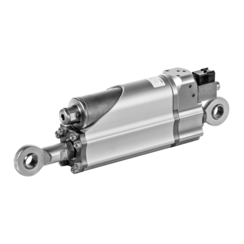
HAWE Hydraulik AC Series Operator's manual
HAWE Hydraulik
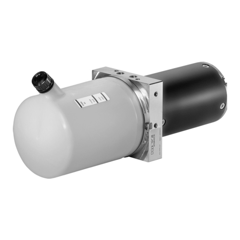
HAWE Hydraulik HLU LE-X User manual
HAWE Hydraulik
HAWE Hydraulik HICON User manual
HAWE Hydraulik
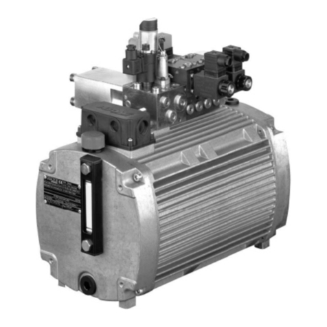
HAWE Hydraulik A 100 User manual

HAWE Hydraulik
HAWE Hydraulik HR 050 User manual
HAWE Hydraulik
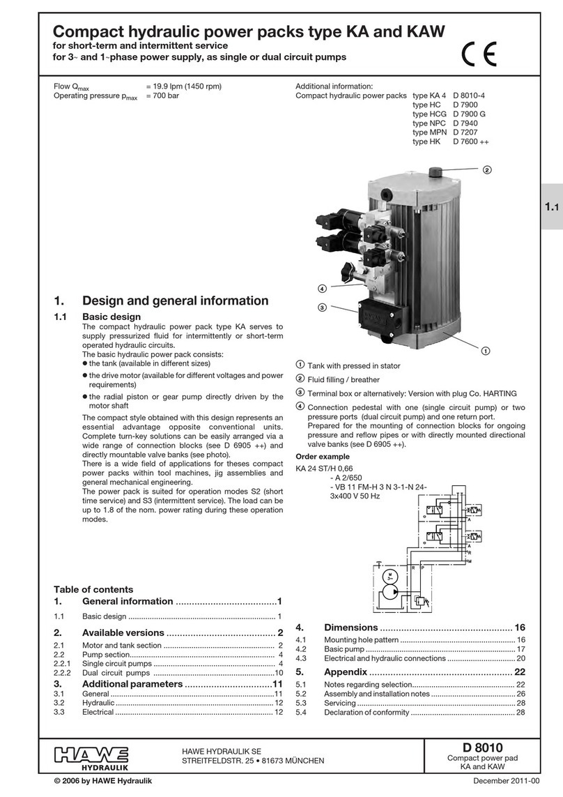
HAWE Hydraulik KA2 User manual
HAWE Hydraulik
HAWE Hydraulik KA User manual
HAWE Hydraulik
HAWE Hydraulik D 7969 AC Operator's manual

