HAWE Hydraulik KA User manual

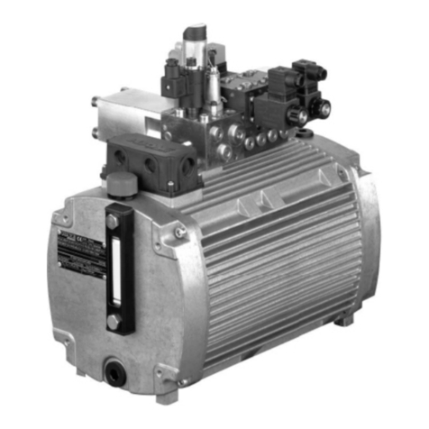
Compact hydraulic power packs type KA and KAW
for short-term and intermittent service
for 3+and 1+phase power supply, as single or dual circuit pumps
D 8010
Compact power pad
KA and KAW
December 2011-00©2006 by HAWE Hydraulik
HAWE HYDRAULIK SE
STREITFELDSTR. 25 • 81673 MÜNCHEN
1.1
Flow Qmax = 19.9 lpm (1450 rpm)
Operating pressure pmax = 700 bar
Additional information:
Compact hydraulic power packs type KA 4 D 8010-4
type HC D 7900
type HCG D 7900 G
type NPC D 7940
type MPN D 7207
type HK D 7600 ++
;Tank with pressed in stator
<Fluid filling / breather
= Terminal box or alternatively: Version with plug Co. HARTING
>Connection pedestal with one (single circuit pump) or two
pressure ports (dual circuit pump) and one return port.
Prepared for the mounting of connection blocks for ongoing
pressure and reflow pipes or with directly mounted directional
valve banks (see D 6905 ++).
1. Design and general information
Order example
KA 24 ST/H 0,66
- A 2/650
- VB 11 FM-H 3 N 3-1-N 24-
3x400 V 50 Hz
1.1 Basic design
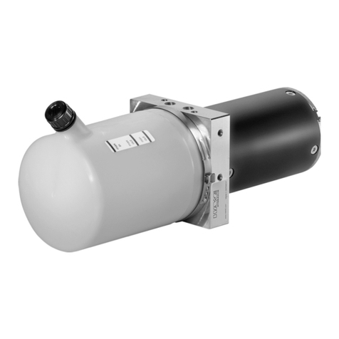
The compact hydraulic power pack type KA serves to
supply pressurized fluid for intermittently or short-term
operated hydraulic circuits.
The basic hydraulic power pack consists:
o the tank (available in different sizes)
othe drive motor (available for different voltages and power
requirements)
othe radial piston or gear pump directly driven by the
motor shaft
The compact style obtained with this design represents an
essential advantage opposite conventional units.
Complete turn-key solutions can be easily arranged via a
wide range of connection blocks (see D 6905 ++) and
directly mountable valve banks (see photo).
There is a wide field of applications for theses compact
power packs within tool machines, jig assemblies and
general mechanical engineering.
The power pack is suited for operation modes S2 (short
time service) and S3 (intermittent service). The load can be
up to 1.8 of the nom. power rating during these operation
modes.
Table of contents
1. General information ......................................1
1.1 Basic design ..................................................................... 1
2. Available versions ......................................... 2
2.1 Motor and tank section .................................................... 2
2.2 Pump section.................................................................... 4
2.2.1 Single circuit pumps ......................................................... 4
2.2.2 Dual circuit pumps ........................................................10
3. Additional parameters .................................11
3.1 General .............................................................................11
3.2 Hydraulic ........................................................................... 12
3.3 Electrical .......................................................................... 12
4. Dimensions .................................................. 16
4.1 Mounting hole pattern ...................................................... 16
4.2 Basic pump ....................................................................... 17
4.3 Electrical and hydraulic connections ................................ 20
5. Appendix ...................................................... 22
5.1 Notes regarding selection................................................ 22
5.2 Assembly and installation notes ........................................ 26
5.3 Servicing ........................................................................... 28
5.4 Declaration of conformity ................................................. 28
;
<
=
>

D 8010 page 2
Coding Power Speed
(kW) (min-1)
KA 21 3+phase motor 0.55 2790 (50 Hz)
0.66 3350 (60 Hz)
KA 22 3+phase motor 1.1 2790 (50 Hz)
1.32 3350 (60 Hz)
KA 23 3+phase motor 0.37 1360 (50 Hz)
0.44 1650 (60 Hz)
KA 24 3+phase motor 0.75 1360 (50 Hz)
0.9 1650 (60 Hz)
KA 26 1) 3+phase motor 1.4 2790 (50 Hz)
1.68 3340 (60 Hz)
KA 28 1) 3+phase motor 1.0 1370 (50 Hz)
1.2 1660 (60 Hz)
KAW 21 1+phase motor 0.37 2770 (50 Hz)
3340 (60 Hz)
KAW 22 1+phase motor 0.75 2810 (50 Hz)
3400 (60 Hz)
KAW 23 1+phase motor 0.25 1380 (50 Hz)
1650 (60 Hz)
KAW 24 1+phase motor 0.50 1390 (50 Hz)
1680 (60 Hz)
KAW 26 1) 1+phase motor 1.10 2770 (50 Hz)
3340 (60 Hz)
KAW 28 1)1+phase motor 0.7 1370 (50 Hz)
1650 (60 Hz)
Basic type
For more detailed information about motor data and available
voltage, see sect. 3.3 in table 9
Table 1a: Basic type and drive power
Table 1b: Tank size
;Connection pedestal, valve assembly, terminal box, options
Motor voltage of the
aux. blower
(table 1d and site 16)
Motor voltage
(table 9)
Tank size
table 1c
Pump version
sect. 2.2
Options
(table 1d)
Fluid drain hose
(table 1f)
KA 24 1 S KS E/H1,81 - A 1/280 - 3x400V 50 Hz
KA 28 22 L1 KTF P/HZ 0,59/8,8-...- 3x400V 50 Hz/24V DC - G 1/2 x 300
Order examples:
2. Available versions, type coding
2.1 Motor and tank section
Electrical port
(table 1e)
Coding Combination
no coding
1
01
11
2
02
21
22
3
Tank size
Filling volume Usable filling volume Usable filling volume
Vfill (l) vertically Vusable (l) horizontal Vusable (l)
3.9 1.85 1.5
5.0 2.7 2.0
5.0 1.85 2.0
6.1 2.95 2.5
7.5 5.45 3.15
7.5 - 3.15
8.6 5.45 3.65
11.1 - 4.8
11.1 8.95 4.8
Note:
A actual
power con-
sumption is
load depen-
dent and can
be up to 1.8
x nominal
power.
1) only availa-
ble with
tank co-
ding 1, 11,
2, 21, 22,
and 3
acc. to
table 1b

D 8010 page 3
Table 1f: Fluid drain hose
Coding Description
no coding Tapped plug G 1/4*
Fluid drain hose G 1/4*x 300 Fluid drain hose approx. 300 mm with ball cock
Fluid drain hose G 1/4*x 500 Fluid drain hose approx. 500 mm with ball cock
Fluid drain hose G 1/4*W x 300 Fluid drain hose approx. 300 mm with elbow and ball cock
Fluid drain hose G 1/4*W x 500 Fluid drain hose approx. 500 mm with elbow and ball cock
Table 1d: Options
Coding Note vertically horizontal
no coding without optional equipments o o
K Fluid level gauge / Fluid level gauge o o
KS Fluid level gauge with float switch (NO-contact) o -
KD Fluid level gauge with float switch (NC-contact) o -
S Float switch (NO-contact) - o
D Float switch (NC-contact) - o
T Temperature switch (switch point 80°C), standard with type KAW o o
T60 Temperature switch (switch point 60°C), only with type KA o o
Silica gel filter (instead of std. breather filter see sect. 5.1k),
Gcan not be retrofitted, o -
not available for versions with auxiliary blower coding F, F1
Auxiliary blower ?
F(see sect. 5.1g) for available o o
motor voltage and other
motor data, see sect. 3.3, table 9a.
Can be retrofitted.
Auxiliary blower ?like
F1 coding F, - o
but on the opposite side
Table 1e: Electrical connection
Note: - The horizontal version can be also installed vertically.
- The vertical version utilizing a radial piston pump (coding H, HH and HZ acc. to sect. 2.2) must not be installed
horizontally
- Regarding
;: For details about the connection block and valve assembly, see sect. 5.1
vertically horizontal
S L L1 L4 L14S14 S25 S36
Table 1c: Installation position
;Connection pedestal, valve assembly, terminal box, <Filler neck with breather filter, =Fluid level gauge
Standard Standard Connection
pedestal
off-set by 90°
Type plate
and fluid level
gauge
=“rear side”
Combination
L1 plus L4
Top and
bottom end
cover off-set
by 90°
Top and
bottom end
cover off-set
by 180°
Top and
bottom end
cover off-set
by 270°
Options
* BSPP
Coding Note
no coding Standard (Terminal box)
P Plug Co. HARTING
P, PM1 with additional connector M12x1 on right or left side for temperature and/or float
E, PE Electrical connection with additional interference suppression in the terminal box or
at the plug Co. HARTING. For alternatives, see sect. 3.3, only with type KA
Means of
electrical
connection

D 8010 page 4
Table 2a: Single circuit pumps with 3+phase motor
Radial piston pump Hor gear pump Z
Note:
The delivery flow rating Qpu is a guide line figure, based on nom. rev. rating that will be slightly reduced dep. on load (see curves
in sect. 3.3). For notes regarding pressure pmax and p1 (see sect. 3.3, table 9).
The max. perm. hydraulic work (pVg)max for version Zwith gear pump has to be reduced by 10%.
The perm. pressure pmax correspond to motors 3+400/230V 50 Hz.
For other voltage: pmax = (pVg)max/Vg. For (pVg)max (see page 13, table 9)
HCoding for radial piston pump
Perm. pressure pmax (bar)
Delivery Qpu (lpm) 50 Hz
60 Hz
Perm. pressure pmax (bar)
Delivery Qpu (lpm) 50 Hz
60 Hz
Piston diameter (mm)
Number of pump elements
Delivery flow coding
Geom. displace Vg (cm3/rev)
KA 21
KA 22
4
3
0,33
0.23
5
3
0,47
0.35
4
6
0,59
0.45
6
3
0,66
0.51
7
3
0,91
0.69
5
6
0,93
0.71
700
0.63
0.76
465
0.99
1.18
360
1.26
1.52
320
1.42
1.70
235
1.93
2.32
230
1.97
2.37
Perm. pressure pmax (bar)
Delivery Qpu (lpm) 50 Hz
60 Hz
KA 26 700
0.63
0.76
700
0.99
1.18
700
1.26
1.52
700
1.42
1.70
700
1.93
2.32
700
1.97
2.37
700
0.63
0.76
700
0.99
1.18
700
1.26
1.52
700
1.42
1.70
700
1.93
2.32
700
1.97
2.37
Perm. pressure pmax (bar)
Delivery Qpu (lpm) 50 Hz
60 Hz
KA 23 700
0.31
0.37
620
0.48
0.58
485
0.62
0.75
430
0.69
0.84
315
0.94
1.14
310
0.96
1.17
Perm. pressure pmax (bar)
Delivery Qpu (lpm) 50 Hz
60 Hz
KA 28 700
0.31
0.37
700
0.48
0.58
700
0.62
0.75
700
0.69
0.84
700
0.94
1.14
700
0.96
1.17
Perm. pressure pmax (bar)
Delivery Qpu (lpm) 50 Hz
60 Hz
KA 24 700
0.31
0.37
700
0.48
0.58
700
0.62
0.75
700
0.69
0.84
700
0.94
1.14
700
0.96
1.17
Perm. pressure pmax (bar)
Delivery Qpu (lpm) 50 Hz
60 Hz
Piston diameter (mm)
Number of pump elements
Delivery flow coding
Geom. displace Vg (cm3/rev)
KA 21
8
3
1,18
0.91
6
6
1,33
1.02
9
3
1,51
1.15
7
6
1,81
1.39
8
6
2,36
1.81
9
6
2,99
2.29
180
2.52
3.03
160
2.84
3.41
140
3.19
3.84
115
3.87
4.64
90
5.05
6.06
70
6.39
7.67
Perm. pressure pmax (bar)
Delivery Qpu (lpm) 50 Hz
60 Hz
KA 26 540
2.52
3.03
570
2.84
3.41
510
3.19
3.84
420
3.87
4.64
320
5.05
6.06
255
6.39
7.67
Perm. pressure pmax (bar)
Delivery Qpu (lpm) 50 Hz
60 Hz
KA 22 570
2.52
3.03
510
2.84
3.41
450
3.19
3.84
370
3.87
4.64
285
5.05
6.06
225
6.39
7.67
Perm. pressure pmax (bar)
Delivery Qpu (lpm) 50 Hz
60 Hz
KA 23 240
1.23
1.49
215
1.38
1.68
190
1.56
1.89
155
1.88
2.29
120
2.46
2.99
95
3.11
3.78
Perm. pressure pmax (bar)
Delivery Qpu (lpm) 50 Hz
60 Hz
KA 28 700
1.23
1.49
670
1.38
1.68
550
1.56
1.89
490
1.88
2.29
375
2.46
2.99
295
3.11
3.78
Perm. pressure pmax (bar)
Delivery Qpu (lpm) 50 Hz
60 Hz
KA 24 650
1.23
1.49
580
1.38
1.68
510
1.56
1.89
425
1.88
2.29
325
2.46
2.99
255
3.11
3.78
2.2 Pump section
2.2.1 Single circuit pumps
Order example 1: KA 242 DT/1 - H6,7 - A1/180 3 x 400V 50Hz
Order example 2: KAW 26/1P1 -Z4,5 - AL11E/120 3 x 400/230V 50Hz

D 8010 page 5
Continuation of table 2a:
Note:
o Version with pump elements type PE acc. to D 5600
o Only available as vertical version (see table 1c)
HCoding for radial piston pump
Perm. pressure pmax (bar)
Delivery Qpu (lpm) 50 Hz
60 Hz
Perm. pressure pmax (bar)
Delivery Qpu (lpm) 50 Hz
60 Hz
Piston diameter (mm)
Number of pump elements
Delivery flow coding
Geom. displace Vg (cm3/rev)
KA 21
KA 22
10
3
1,84
1.41
12
3
2,66
2.04
13
3
3,12
2.39
14
3
3,61
2.77
10
6
3,69
2.83
15
3
4,14
3.18
115
3.90
4.69
80
5.65
6.79
65
6.62
7.96
55
7.67
9.22
55
7.84
9.42
50
8.81
10.59
Perm. pressure pmax (bar)
Delivery Qpu (lpm) 50 Hz
60 Hz
KA 26 410
3.90
4.69
285
5.65
6.79
240
6.62
7.96
210
7.67
9.22
205
7.84
9.42
180
8.81
10.59
365
3.90
4.69
250
5.65
6.79
215
6.62
7.96
185
7.67
9.22
180
7.84
9.42
160
8.81
10.59
Perm. pressure pmax (bar)
Delivery Qpu (lpm) 50 Hz
60 Hz
KA 23 155
1.91
2.31
105
2.76
3.34
90
3.23
3.91
75
3.74
4.54
75
3.83
4.63
65
4.30
5.21
Perm. pressure pmax (bar)
Delivery Qpu (lpm) 50 Hz
60 Hz
KA 28 485
1.91
2.31
335
2.76
3.34
285
3.23
3.91
245
3.74
4.54
240
3.83
4.63
215
4.30
5.21
Perm. pressure pmax (bar)
Delivery Qpu (lpm) 50 Hz
60 Hz
KA 24 415
1.91
2.31
285
2.76
3.34
245
3.23
3.91
210
3.74
4.54
205
3.83
4.63
185
4.30
5.21
Perm. pressure pmax (bar)
Delivery Qpu (lpm) 50 Hz
60 Hz
Piston diameter (mm)
Number of pump elements
Delivery flow coding
Geom. displace Vg (cm3/rev)
KA 21
16
3
4,72
3.62
12
6
5,31
4.07
13
6
6,24
4.78
14
6
7,23
5.54
15
6
8,29
6.36
16
6
9,45
7.24
45
10.02
12.05
Perm. pressure pmax (bar)
Delivery Qpu (lpm) 50 Hz
60 Hz
KA 26 160
10.02
12.05
Perm. pressure pmax (bar)
Delivery Qpu (lpm) 50 Hz
60 Hz
KA 22 140
10.02
12.05
Perm. pressure pmax (bar)
Delivery Qpu (lpm) 50 Hz
60 Hz
KA 23 60
4.89
5.93
50
5.50
6.66
45
6.46
7.83
35
7.49
9.07
30
8.60
10.41
30
9.79
11.85
Perm. pressure pmax (bar)
Delivery Qpu (lpm) 50 Hz
60 Hz
KA 28 185
4.89
5.93
165
5.50
6.66
140
6.46
7.83
120
7.49
9.07
105
8.60
10.41
90
9.79
11.85
Perm. pressure pmax (bar)
Delivery Qpu (lpm) 50 Hz
60 Hz
KA 24 160
4.89
5.93
140
5.50
6.66
120
6.46
7.83
105
7.49
9.07
90
8.60
10.41
80
9.79
11.85

D 8010 page 6
ZCoding for gear Size 1
Perm. pressure pmax (bar)
Delivery Qpu (lpm) 50 Hz
60 Hz
Perm. pressure pmax (bar)
Delivery Qpu (lpm) 50 Hz
60 Hz
Delivery flow coding
Geom. displace Vg (cm3/rev)
KA 21
KA 22
Z 1,1
0.8
Z 1,7
1.1
Z 2,0
1.4
Z 2,7
1.9
Z 3,5
2.4
Z 4,5
3.1
170
2.23
2.68
130
3.07
3.69
100
3.91
4.69
75
5.30
6.37
60
6.70
8.04
170
2.23
2.68
170
3.07
3.69
170
3.91
4.69
170
5.30
6.37
170
6.70
8.04
150
8.65
10.39
Perm. pressure pmax (bar)
Delivery Qpu (lpm) 50 Hz
60 Hz
KA 23 170
1.09
1.32
170
1.50
1.82
140
1.90
2.31
100
2.58
3.14
80
3.26
3.96
60
4.22
5.12
Perm. pressure pmax (bar)
Delivery Qpu (lpm) 50 Hz
60 Hz
KA 24 170
1.09
1.32
170
1.50
1.82
170
1.90
2.31
170
2.58
3.14
170
3.26
3.96
170
4.22
5.12
Perm. pressure pmax (bar)
Delivery Qpu (lpm) 50 Hz
60 Hz
Delivery flow coding
Geom. displace Vg (cm3/rev)
KA 21
Z 5,2
3.6
Z 6,4
4.4
Z 6,9
4.8
Z 8,8
6.1
Z 9,8
7.0
Z11,3
7.9
Perm. pressure pmax (bar)
Delivery Qpu (lpm) 50 Hz
60 Hz
KA 22 130
10.04
12.06
105
12.28
14.74
95
13.39
16.08
75
17.02
20.44
65
19.53
23.45
55
22.04
26.47
Perm. pressure pmax (bar)
Delivery Qpu (lpm) 50 Hz
60 Hz
KA 23 50
4.90
5.94
Perm. pressure pmax (bar)
Delivery Qpu (lpm) 50 Hz
60 Hz
KA 24 145
4.90
5.94
120
5.98
7.26
110
6.53
7.92
85
8.30
10.07
75
9.52
11.55
65
10.74
13.04
Perm. pressure pmax (bar)
Delivery Qpu (lpm) 50 Hz
60 Hz
Perm. pressure pmax (bar)
Delivery Qpu (lpm) 50 Hz
60 Hz
KA 26
KA 28
170
2.23
2.68
170
3.07
3.69
170
3.91
4.69
170
5.30
6.37
170
6.70
8.04
170
8.65
10.39
170
1.09
1.32
170
1.50
1.82
170
1.90
2.31
170
2.58
3.14
170
3.26
3.96
170
4.22
5.12
Perm. pressure pmax (bar)
Delivery Qpu (lpm) 50 Hz
60 Hz
KA 26 145
10.04
12.06
120
12.28
14.74
110
13.39
16.08
85
17.02
20.44
75
19.53
23.45
65
22.04
26.47
Perm. pressure pmax (bar)
Delivery Qpu (lpm) 50 Hz
60 Hz
KA 28 170
4.90
5.94
140
5.98
7.26
125
6.53
7.92
100
8.30
10.07
85
9.52
11.55
75
10.74
13.04
Continuation of table 2a:

D 8010 page 7
HCoding for radial piston pump
Perm. pressure pmax (bar)
Delivery Qpu (lpm) 50 Hz
60 Hz
Perm. pressure pmax (bar)
Delivery Qpu (lpm) 50 Hz
60 Hz
Piston diameter (mm)
Number of pump elements
Delivery flow coding
Geom. displace Vg (cm3/rev)
KAW 23
KAW 24
4
3
0,33
0.23
5
3
0,47
0.35
4
6
0,59
0.45
6
3
0,66
0.51
7
3
0,91
0.69
5
6
0,93
0.71
640
0.31
0.37
410
0.48
0.58
320
0.62
0.75
285
0.69
0.84
205
0.94
1.14
205
0.96
1.17
700
0.31
0.37
700
0.48
0.58
700
0.62
0.75
685
0.69
0.84
505
0.94
1.14
495
0.96
1.17
Perm. pressure pmax (bar)
Delivery Qpu (lpm) 50 Hz
60 Hz
KAW 26 700
0.63
0.76
700
0.99
1.18
605
1.26
1.52
540
1.42
1.70
395
1.93
2.32
385
1.97
2.37
Perm. pressure pmax (bar)
Delivery Qpu (lpm) 50 Hz
60 Hz
KAW 28 700
0.31
0.37
700
0.48
0.58
700
0.62
0.75
700
0.69
0.84
575
0.94
1.14
565
0.96
1.17
Perm. pressure pmax (bar)
Delivery Qpu (lpm) 50 Hz
60 Hz
Piston diameter (mm)
Number of pump elements
Delivery flow coding
Geom. displace Vg (cm3/rev)
KAW 23
8
3
1,18
0.91
6
6
1,33
1.02
9
3
1,51
1.15
7
6
1,81
1.39
8
6
2,36
1.81
9
6
2,99
2.29
160
1.23
1.49
140
1.38
1.68
125
1.56
1.89
105
1.88
2.29
80
2.46
2.99
60
3.11
3.78
Perm. pressure pmax (bar)
Delivery Qpu (lpm) 50 Hz
60 Hz
KAW 24 385
1.23
1.49
340
1.38
1.68
305
1.56
1.89
250
1.88
2.29
190
2.46
2.99
150
3.11
3.78
Perm. pressure pmax (bar)
Delivery Qpu (lpm) 50 Hz
60 Hz
KAW 26 300
2.52
3.03
270
2.84
3.41
240
3.19
3.84
195
3.87
4.64
150
5.05
6.06
120
6.39
7.67
Perm. pressure pmax (bar)
Delivery Qpu (lpm) 50 Hz
60 Hz
KAW 28 440
1.23
1.49
390
1.38
1.68
345
1.56
1.89
285
1.88
2.29
220
2.46
2.99
175
3.11
3.78
Table 2b: Single circuit pumps with 1+phase motor
Radial piston pump Hor gear pump Z
Perm. pressure pmax (bar)
Delivery Qpu (lpm) 50 Hz
60 Hz
KAW 21 440
0.63
0.76
280
0.99
1.18
221
1.26
1.52
195
1.42
1.70
140
1.93
2.32
140
1.97
2.37
Perm. pressure pmax (bar)
Delivery Qpu (lpm) 50 Hz
60 Hz
KAW 22
110
2.52
3.03
95
2.84
3.41
85
3.19
3.84
70
3.87
4.64
55
5.05
6.06
40
6.39
7.67
Perm. pressure pmax (bar)
Delivery Qpu (lpm) 50 Hz
60 Hz
KAW 21
700
0.63
0.76
650
0.99
1.18
505
1.26
1.52
450
1.42
1.70
330
1.93
2.32
325
1.97
2.37
Perm. pressure pmax (bar)
Delivery Qpu (lpm) 50 Hz
60 Hz
KAW 22 250
2.52
3.03
225
2.84
3.41
200
3.19
3.84
165
3.87
4.64
120
5.05
6.06
100
6.39
7.67
HCoding for radial piston pump
Note:
The delivery flow rating Qpu is a guide line figure, based on nom. rev. rating that will be slightly reduced dep. on load
(see curves in sect. 3.3). For notes regarding pressure pmax and p1 (see sect. 3.3, table 9).
The perm. pressure pmax correspond to motors 1 x 230V 50 Hz
For other voltage: pmax = (pVg)max/Vg. For (pVg)max see page 16, table 9
The max. perm. hydraulic work (pVg)max for version Zwith gear pump has to be reduced by 10%.
A capacitor is mandatory for the version with 1+phase motor, which is not scope of delivery. For recommendations and
notes regarding selection, see sect. 3.3 and. 5.1i.
These power packs won‘t start-up against pressure!

D 8010 page 8
Continuation of table 2b:
Note:
o Version with pump elements type PE acc. to D 5600
o Only available as vertical version (see table 1c)
HCoding for radial piston pump
Perm. pressure pmax (bar)
Delivery Qpu (lpm) 50 Hz
60 Hz
Perm. pressure pmax (bar)
Delivery Qpu (lpm) 50 Hz
60 Hz
Piston diameter (mm)
Number of pump elements
Delivery flow coding
Geom. displace Vg (cm3/rev)
KAW 21
KAW 22
10
3
1,84
1.41
12
3
2,66
2.04
13
3
3,12
2.39
14
3
3,61
2.77
10
6
3,69
2.83
15
3
4,14
3.18
70
3.86
4.66
45
5.59
6.74
40
6.55
7.90
35
7.59
9.15
35
7.75
9.35
30
8.71
10.51
Perm. pressure pmax (bar)
Delivery Qpu (lpm) 50 Hz
60 Hz
KAW 26 195
3.86
4.6
130
5.59
6.74
115
6.55
7.90
95
7.59
9.15
95
7.75
9.35
85
8.71
10.51
160
3.86
4.66
110
5.59
6.74
95
6.55
7.90
80
7.59
9.15
80
7.75
9.35
70
8.71
10.51
Perm. pressure pmax (bar)
Delivery Qpu (lpm) 50 Hz
60 Hz
KAW 23 100
1.90
2.27
70
2.75
3.28
60
3.22
3.84
50
3.73
4.46
50
3.81
4.55
45
4.29
5.12
Perm. pressure pmax (bar)
Delivery Qpu (lpm) 50 Hz
60 Hz
KAW 28 280
1.90
2.27
195
2.75
3.28
165
3.22
3.84
140
3.73
4.46
140
3.81
4.55
125
4.29
5.12
Perm. pressure pmax (bar)
Delivery Qpu (lpm) 50 Hz
60 Hz
KAW 24 245
0.00
2.27
170
2.75
3.28
145
3.22
3.84
125
3.73
4.46
120
3.81
4.55
100
4.29
5.12
Perm. pressure pmax (bar)
Delivery Qpu (lpm) 50 Hz
60 Hz
Piston diameter (mm)
Number of pump elements
Delivery flow coding
Geom. displace Vg (cm3/rev)
KAW 21
16
3
4,72
3,.2
12
6
5,31
4.07
13
6
6,24
4.78
14
6
7,23
5.54
15
6
8,29
6.36
16
6
9,45
7.24
25
9.92
11.96
Perm. pressure pmax (bar)
Delivery Qpu (lpm) 50 Hz
60 Hz
KAW 26 75
9.92
11.96
Perm. pressure pmax (bar)
Delivery Qpu (lpm) 50 Hz
60 Hz
KAW 22 60
9.92
11.96
Perm. pressure pmax (bar)
Delivery Qpu (lpm) 50 Hz
60 Hz
KAW 23 40
4.88
5.82
35
5.49
6.55
30
6.44
7.69
25
7.47
8.91
20
8.57
10.23
20
9.76
11.65
Perm. pressure pmax (bar)
Delivery Qpu (lpm) 50 Hz
60 Hz
KAW 28 110
4.88
5.82
95
5.49
6.55
80
6.44
7.69
70
7.47
8.91
60
8.57
10.23
55
9.76
11.65
Perm. pressure pmax (bar)
Delivery Qpu (lpm) 50 Hz
60 Hz
KAW 24 95
4.88
5.82
85
5.49
6.55
70
6.44
7.69
60
7.47
8.91
55
8.57
10.23
45
9.76
11.65

D 8010 page 9
ZCoding for gear Size 1
Perm. pressure pmax (bar)
Delivery Qpu (lpm) 50 Hz
60 Hz
Perm. pressure pmax (bar)
Delivery Qpu (lpm) 50 Hz
60 Hz
Delivery flow coding
Geom. displace Vg (cm3/rev)
KAW 23
KAW 24
Z 1,1
0.8
Z 1,7
1.1
Z 2,0
1,4
Z 2,7
1.9
Z 3,5
2.4
Z 4,5
3.1
160
1.09
1.32
115
1.50
1.82
90
1.90
2.31
65
2.58
3.14
50
3.26
3.96
170
1.09
1.32
170
1.50
1.82
170
1.90
2.31
165
2.58
3.14
130
3.26
3.96
100
4.22
5.12
Perm. pressure pmax (bar)
Delivery Qpu (lpm) 50 Hz
60 Hz
KAW 26 170
2.23
2.68
170
3.07
3.69
170
3.91
4.69
130
5.30
6.37
100
6.70
8.04
80
8.65
10.39
Perm. pressure pmax (bar)
Delivery Qpu (lpm) 50 Hz
60 Hz
KAW 28 170
1.09
1.32
170
1.50
1.82
170
1.90
2.31
170
2.58
3.14
150
3.26
3.96
115
4.22
5.12
Perm. pressure pmax (bar)
Delivery Qpu (lpm) 50 Hz
60 Hz
Delivery flow coding
Geom. displace Vg (cm3/rev)
KAW 23
Z 5,2
3.6
Z 6,4
4.4
Z 6,9
4.8
Z 8,8
6.1
Z 9,8
7.0
Z11,3
7.9
Perm. pressure pmax (bar)
Delivery Qpu (lpm) 50 Hz
60 Hz
KAW 24 85
4.90
5.94
70
5.98
7.26
65
6.53
7.92
50
8.30
10.07
Perm. pressure pmax (bar)
Delivery Qpu (lpm) 50 Hz
60 Hz
KAW 26 65
10.04
12.06
55
12.28
14.74
50
13.39
16.08
Perm. pressure pmax (bar)
Delivery Qpu (lpm) 50 Hz
60 Hz
KAW 28 100
4.90
5.94
80
5.98
7.26
75
6.53
7.92
50
8.30
10.07
50
9.52
11.55
Perm. pressure pmax (bar)
Delivery Qpu (lpm) 50 Hz
60 Hz
KAW 21 110
2.23
2.68
80
3.07
3.69
60
3.91
4.69
Perm. pressure pmax (bar)
Delivery Qpu (lpm) 50 Hz
60 Hz
KAW 22 170
2.23
2.68
170
3.07
3.69
145
3.91
4.69
105
5.30
6.37
85
6.70
8.04
65
8.65
10.39
Perm. pressure pmax (bar)
Delivery Qpu (lpm) 50 Hz
60 Hz
KAW 21
Perm. pressure pmax (bar)
Delivery Qpu (lpm) 50 Hz
60 Hz
KAW 22 55
10.04
12.06
Continuation of table 2b:

D 8010 page 10
2.2.2 Dual circuit pump with joint connection pedestal
a) Version radial piston pump -- radial piston pump HH
and radial piston pump -- gear pump coding HZ
Pressure connection P1
Radial piston pump H acc. to table 3
Pressure connection P3:
Radial piston pump Hor gear pump Z
acc. to table 4
Table 3: Pressure connection P1
Note: The delivery flow rating Qpu is a guide line figure, based on nom. rev. rating that will be slightly reduced dep. on
load (see sect. 3.3). For notes regarding pressure pmax and p1 (see sect. 3.3, table 9).
The max. perm. hydraulic work (pVg)max for version HH and HZ with gear pump has to be reduced by 10%.
Order example 1: KAW 24 1 S KS E / H H 0,34 / 2,0 - NA31 - ... 1 + 230V 50 Hz
Order example 2: KA 24 11 S KS E / H Z 0,34 / 6,9 - NA31 - ... 3 + 400V 50 Hz
HCoding for radial piston pump
Piston diameter (mm)
Number of pump elements
Delivery flow coding
Geom. displace Vg (cm3/rev)
4
3
0,33
0.23
5
3
0,47
0.35
6
3
0,66
0.51
7
3
0,91
0.69
8
3
1,18
0.91
9
3
1,51
1.15
Piston diameter (mm)
Number of pump elements
Delivery flow coding
Geom. displace Vg (cm3/rev)
4
2
0,21
0.15
5
2
0,34
0.24
6
2
0,48
0.34
7
2
0,62
0.46
8
2
0,78
0.60
9
2
0,99
0.76
Piston diameter (mm)
Number of pump elements
Delivery flow coding
Geom. displace Vg (cm3/rev)
4
6
0,59
0.45
5
6
0,93
0.71
6
6
1,33
1.02
7
6
1,81
1.39
8
6
2,36
1.81
9
6
2,99
2.29
Piston diameter (mm)
Number of pump elements
Delivery flow coding
Geom. displace Vg (cm3/rev)
4
9
0,85
0.68
5
9
1,38
1.06
6
9
2,01
1.53
7
9
2,71
2.08
8
9
3,54
2.71
9
9
4,49
3.44
HCoding for radial piston pump
Piston diameter (mm)
Number of pump elements
Delivery flow coding
Geom. displace Vg (cm3/rev)
4
3
0,33
0.23
5
3
0,47
0.35
6
3
0,66
0.51
7
3
0,91
0.69
8
3
1,18
0.91
9
3
1,51
1.15
Piston diameter (mm)
Number of pump elements
Delivery flow coding
Geom. displace Vg (cm3/rev)
4
4
0,38
0.30
5
4
0,58
0.47
6
4
0,86
0.68
7
4
1,21
0.92
8
4
1,59
1.21
9
4
2,00
1.53
Piston diameter (mm)
Number of pump elements
Delivery flow coding
Geom. displace Vg (cm3/rev)
4
6
0,59
0.45
5
6
0,93
0.71
6
6
1,33
1.02
7
6
1,81
1.39
8
6
2,36
1.81
9
6
2,99
2.29
Delivery flow coding
Geom. displace Vg (cm3/rev)
1,1
0.8
1,7
1.1
2,0
1.4
2,7
1.9
3,5
2.4
4,5
3.1
Delivery flow coding
Geom. displace Vg (cm3/rev)
5,2
3.6
6,4
4.4
6,9
4.8
8,8
6.1
9,8
7.0
11,3
7.9
ZCoding for gear
Table 4: Pressure connection P3
radial piston pump Hor gear pump coding Zfor available combinations, see above
Note: The delivery flow rating Qpu is a guide line figure, based on nom. rev. rating that will be slightly reduced dep. on
load (see sect. 3.3). For notes regarding pressure pmax and p1 (see sect. 3.3, table 9).
Available combinations
Coding P1 P3
HH
HZ
3 pump elements
2 pump elements
6 pump elements
3 pump elements
3 pump elements
6 pump elements
3 pump elements
4 pump elements
6 pump elements
9 pump elements
Gear pump size 1
Gear pump size 1
Example
HH 0,66/1,18
HH 0,34/0,86
HH 0,93/0,93
HH 0,47/2,01
HZ 0,33/9,8
HZ 0,59/8,8
Note: Pump versions coding HZ are only available for tank size codings

D 8010 page 11
Nomenclature Constant delivery pump
Design Valve controlled radial piston pump or gear pump
Direction of rotation Radial piston pump - any
Gear pump - counterclockwise
(Direction of rotation can only be detected by checking the delivery flow - the connection of 2 of the 3
leads have to be changed at 3-phase versions, when there is no flow)
Speed range Radial piston pump H: 200 ... 3500 rpm
Gear pump Z 1,1 ... Z 6,9: 700 ... 4000 rpm
Z 8,8 ... Z 11,3: 500 ... 1800 rpm
Installed position Vertically (KA...S) or horizontally (KA...L)
Observe notes regarding horizontal version, see sect. 4.2
Mounting Tapped holed M8, see dimensional drawings
Mass (weight) H (3 cyl.) H (6 cyl.) Z HZ
(without fluid) KA 21, 23 10.9 11.5 12.7 13.2
KA 22, 24 13.2 13.6 15.0 15.5
KA 26, 28 14.7 15.1 16.5 17.0
Tank size 01, 1 +0.7 kg
Tank size 02, 2 +2.2 kg
Tank size 11 +1.4 kg
Tank size 21 +2.9 kg
Tank size 22, 3 +4.4 kg
Auxilliary blower +1.8 kg
Hydraulic connection via directly mounted connection blocks, see table in sect. 5.1l
Basic pump: For connection hole pattern, see sect. 4
Silica gel filter Filtering surface 26.6 cm2
Content 136 g
Absorbance capacity 29.6 ml
Filtration 3 mm
Temperature range -30°C ... +90°C
Note: For maintenance rules, see sect. 5.3!
Running noise
3. Additional parameters
3.1 General
For Mass (weight) of the required connec-
tion blocks, see the respective pamphlets
(listing in sect. 5.1l and 5.1m)
Radial piston pump
Gear pump
Hydraulic work pVg(bar cm3) Hydraulic work pVg(bar cm3)
Noise level dB (A)
Noise level dB (A)

D 8010 page 12
Pressure Delivery side (outlet ports P) depending on pump design and delivery flow, see sect. 2.2
Suction side (inside the tank): ambient pressure. Not suitable for charging.
Starting against pressure Versions with 3+phase motor will start-up against pressure pmax! Whereas versions with 1+phase
motor will start-up only against slight pressure!
3.2 Hydraulic
Filling and usable volume
Pressure fluid Hydraulic oil conforming DIN 51 524 part 1 to 3; ISO VG 10 to 68 conforming DIN 51 519
Opt. operation range: Radial piston pump H: 10 ... 500 mm2/s
Gear pump Z: 20 ... 100 mm2/s
Viscosity range: min. approx. 4; max. approx. 800 mm2/s
Also suitable are biologically degradable pressure fluids type HEES (synth. Ester) at service tempera-
tures up to approx. +70°C. Electrically hazardous: Any fluid types containing water must not be used
(short-cut).
Temperature Ambient: approx. -40 ... +80°C; Fluid: -25 ... +80°C. Note the viscosity range!
Permissible temperature during start: -40°C (observe start-viscosity!), as long as the service tempera-
ture is at least 20K higher for the following operation. Biologically degradable pressure fluids: Observe
manufacturer’s specifications. By consideration of the compatibility with seal material not over +70°C.
See tank size in sect. 2.1, table 1b
3.3 Electrical
The following data apply to radial piston and to gear pumps The drive motor is part of the pump and can not be removed, see
description in sect. 1.
Connection Versions with plug Co. HARTING: cable 1.5 mm2
Versions with integrated terminal box: Blade type plugs 6.3 Co. AMP
Cable gland M20x1.5 or connector. M12x1 (option PM) are not scope of delivery.
Protection class IP 65 acc. to IEC 60529
Note: The breather filter has to be protected from migrating moisture.
Safety class DIN VDE 0100 safety class 1
Insulation Lay-out conf. EN 60 664-1
o up to 500V AC nom. phase voltage (wire-wire) for 4-wire AC-mains L1-L2-L3-PE (3+phase mains)
with earthed star connection point.
o up to 300V AC nom. phase voltage (wire-wire) for 3-wire AC-mains L1-L2-L3 (3+phase mains)
without earthed star connection point.
o for 1~phase mains with 2 conductors L-N up to 300 V AC nom. voltage.
Suppressor Type RC3R
Coding E, PE Oper. voltage 3x 575V AC
Frequency 10 ... 400 Hz
Max. power 4.0 kW

D 8010 page 13
Note:
oThe current consumption of the motor depends strongly on its load. The nominal figures apply strictly to one operating point only.
Up to 1.8 of the nominal power of the motor can be exploited during load / no load operation (= operation mode
S2 and S3). The increased heat built-up under these conditions gets intensively radiated during the idle or stand-still periods.
oThe respective current consumption can be estimated via the middled and max. figures for the hydraulic work
(pVg)mand (pVg)max.
oThe respective load is determining for the current consumption of dual circuit pumps. The hydraulic work of the individual
circuits have to be determined and added up.
Type
KA 21
Nom. voltage and
mains frequency
UN (V), f (Hz)
3x400/230V 50 Hz !/
3x460/265V 60 Hz !/
3x690V 50 Hz !
Nominal
power
PN (kW)
0.55
0.66
0.55
Nom.
speed
nN
(rpm)
2790
3350
2790
Nom.
current
IN(A)
1.25/2.2
1.3/2.25
0.73
Start current
ratio
IA / IN
4.8
5.4
4.8
Power
factor
cos j
0.84
0.88
0.84
Rec.
operating
capacitor
CB(µF)
KA 22 3x400/230V 50 Hz !/
3x460/265V 60 Hz !/
3x690V 50 Hz !
3x200V 50 Hz/60 Hz
1.1
1.32
1.1
1.1
2790
3400
2790
2820/3380
2.7/4.7
2.6/4.5
1.55
5.5/4.9
5.4
7.1
6.3
5.4/6.2
0.83
0.80
0.83
0.74/0.88
KA 23 3x400/230 V 50 Hz !/
3x460/265 V 60 Hz !/
0.37
0.44
1360
1650
1.0/1.75
1.0/1.75
4.3
4.4
0.80
0.81
KA 24 3x400/230V 50 Hz !/
3x460/265V 60 Hz !/
3x200V 50 Hz/60 Hz
0.75
0.9
0.75
1360
1650
1390/1680
2.2/3.8
2.1/3.6
4.5/3.9
4.3
5.4
4.8
0.74
0.74
0.67
KA 26
KA 28
3x400/230 V 50 Hz !/
3x460/265 V 60 Hz !/
3x500V 50 Hz !
3x575V 60 Hz !
3x380V 60 Hz !
3x200V 50 Hz/60 Hz !
1.4
1.68
1.4
1.4
1.4
1.4
2750
3340
2820
3450
3450
2840/3450
3.0/5.2
3.0/5.2
2.35
2.0
3.05
6.4/5.3
5.1
5.0
6.0
7.1
7.1
6.2/7.1
0.89
0.90
0.85
0.86
0.86
0.79/0.86
max.
hydraulic
work (pVg)max
(bar cm3)
165
165
165
520
520
490
490/350
220
220
3x690V 50 Hz !
3x575V 60 Hz ! S3
3x200V 50 Hz/60 Hz S3
0.75
0.75
0.37
1330
1670
1410/1690
1.3
1.4
2.3/2.0
3.0
3.8
4.8
0.75
0.75
0.67
385
360
290/210
590
590
610/460
KAW 26 1x230V 50 Hz (
1x110V 60 Hz (
1x220V 60 Hz (
1x115V 50 Hz (
1.1
1.1
1.1
1.1
2770
3340
3340
2750
7.2
15.0
7.2
15.0
4.8
4.0
4.0
4.0
0.98
0.99
0.99
0.96
32
100
25
120
275
235
275
260
585
585
590
590
630
630
Table 9: Motor data
3x400/230V 50 Hz !/
3x460/265V 60 Hz !/
3x200V 50 Hz/60 Hz
1.0
1.2
1.1
1370
1660
1390/1690
2,55/4,4
2,5/4,35
6.3/5.5
4.8
5.0
5.1
0.76
0.78
0.67/0.76
685
685
785/665
KAW 21 1x230V 50 Hz (
1x110V 60 Hz (
0.37
0.37
2770
3340
2.5
5.5
3.7
3.0
0.97
0.96
24
50
100
70
KAW 22 1x230V 50 Hz (
1x110V 60 Hz (
0.75
0.75
2810
3400
4.75
12.0
4.4
3.5
0.94
0.90
32
120
230
175
KAW 23 1x230V 50 Hz (
1x110V 60 Hz (
0.25
0.25
1380
1650
1.9
4.4
3.0
3.2
0.91
0.96
18
50
145
100
KAW 28 1x230V 50 Hz (
1x110V 60 Hz (
0.7
0.7
1370
1650
5.1
10.5
3.0
3.0
0.94
0.98
36
100
400
315
KAW 24 1x230V 50 Hz (
1x110V 60 Hz (
1x220V 60 Hz (
0.5
0.5
0.5
1390
1680
1680
4.1
9.0
3.9
2.9
3.3
2.9
0.95
0.98
0.98
32
65
25
350
210
275
o Versions with 1+phase motors. The actual current consumption also depends on the size of the operating capacitor. The
operating capacitor is not scope of delivery. For selection, see sect. 5.1 e
o Tension tolerances: *10% (IEC 38), at 3 x 460/265V 60 Hz *5%
It is possible to use the power pack with reduced voltage, but this will cause a reduced performance, see sect. 5.1e !
The max. perm. hydraulic work (pVg)max for version Z, HH, and HZ with gear pump has to be reduced by 10%.
p1, Vg1
p3, Vg3
Dual circuit pumps (p ·Vg) calc. = p1Vg1 + p3Vg3
All pressure out-
lets pressurized:
p1, Vg1
p3 = |pL2)
Dual circuit pumps (p ·Vg) calc. = p1Vg1 + |pLVg3
One pressure out-
let is pressurized,
the other one in idle
circulation mode:

D 8010 page 14
KA 23
KA 24
KA 28
Oper. voltage 3 x 400/230V 50 Hz !/
3 x 460/265V 60 Hz !/
Motor current IM (A) 400 V 50 Hz
(460 V 60 Hz)
Delivery flow characteristic (tendency) 1.0 = Qpu
Hydraulic work (pVg) (bar cm3)
KA 21
KA 22
KA 26
Oper. voltage 3 x 400/230V 50 Hz !/
3 x 460/265V 60 Hz !/
Motor current IM (A) 400 V 50 Hz
(460 V 60 Hz)
Hydraulic work (pVg) (bar cm3)
Current consumption
Delivery flow characteristic (tendency) 1.0 = Qpu

D 8010 page 15
KAW 21
KAW 22
KAW 26
Oper. voltage 1 x 230V 50 Hz
1 x 110V 60 Hz
KAW 23
KAW 24
KAW 28
Oper. voltage 1 x 230V 50 Hz
1 x 110V 60 Hz
Motor current IM (A) Motor current IM (A)
Hydraulic work (pVg) (bar cm3)

D 8010 page 16
4. Dimensions All dimensions in mm, subject to change without notice!
UN P
N(W) Revolutions Protection class
(rpm)
1x230V 50/ 60 Hz ( 45 2800/ 3250 IP 44
1x110V 60 Hz ( 38 3250 IP 44
24V DC 12 3050 IP 20
Temperature switch
Coding T
Technical data:
Bimetallic switch
winding protective switch KAW
separately mounted KA
Temperature switch
Trigger point 80°C *5K (Coding T)
60°C * 5K (Coding T60)
Max. voltage 250 V 50/60 Hz
Nom. current (cos j ~0,6) 1.6 A
Max. current at 24 V (cos j= 1) 1.5 A
Electrical connection Terminal box / plug Co. HARTING
Technical data:
Max. switched power DC/AC 60 W/ 60 VA
Max. current DC/AC 0.8 A (cos j=1)
Max. voltage 230 V 50/60 Hz
Max. switched power DC/AC 10 W
Max. current DC/AC 1 A
Max. voltage 150 V 50/60 Hz
200V DC
A protective circuitry has to be employed at inductive loads!
Float switch
Coding D, S (horizontal)
Coding KD, KS (vertically)
}
DS
(NC-contact) (NO-contact)
Aux. blower
Coding F, F1
Motor data
Temperature range -30°C ... +50°C
Electrical connection Plug conf. DIN EN 175 301-803 A
4.1 Mounting hole pattern
Horizontal version coding L
Vertical version coding S
Recommended mounting
Coding
Tank size a
- 284
01, 1 336
11 388
02, 2 484
22, 3 684
Silent bloc #40x30 /M8 (65 Shore)

D 8010 page 17
Tank size
Coding 01, 11, 21
1) There is an additional fluid gauge in the tank extension
with tank size coding 1, 2, 11, 21, 3 and optional fluid
gauge coding K, KS, KD.
Whereas tank size 3 features the fluid gauge only in the
tank extension.
Filler G 1/2 (BSPP)
with breather (40 µm)
Fluid level gauge
K, KS, KD
Fluid drain G 1/2 (BSPP)
For fluid drain hose, see page 19
Position with coding S14
Position with
Coding S25
Position with
Coding S26
Tank size
Coding 2, 3
M8, 15 deep
(4x at both ends of the pump)
4xM8, 15 deep
1)
1)
Tank size Coding 1
Connection pedestal
with connection block;
Example: A1/...
see sect. 5.1l
Terminal box
Coding P,
see page 19
Tank size without coding
Suppressor
Coding E
4.2 Basic pump
Vertical version

D 8010 page 18
Horizontal version
Fluid level gauge K
Example:
Connection block A1/...
Terminal box
(coding P see page 19)
Filler G 1/2 (BSPP)
with breather (40 µm)
4xM8, 15 deep
Tank size
Coding 1
Tank size
Coding 01, 11, 02, 22
Position with
Coding L1, L14
Tank size without coding
Fluid drain G 1/2 (BSPP)
For fluid drain hose
(see page 19)
Tank size
Coding 2, 3
Note: In case a version intended for horizontal use is installed
vertically the breather has to be positioned on top and the
pump at the bottom.

D 8010 page 19
Options
Terminal box
Coding P
Suppressor
Coding PE
Fluid drain hose
Coding G 1/2 x 300
G 1/2 x 500
Coding G 1/2 W x 300
G 1/2 W x 500
Min distance
Silica gel filter
Coding G
Aux. blower
Coding F, F1
Horizontal version Vertical version
Min distanceElectr. connection
aux. blower

D 8010 page 20
CB- operating capacitor
(not scope of delivery)
4.3 Electrical and hydraulic connections
Hydraulical
2xM8, 13 deep
2xM6, 13 deep
Electrical
Terminal box
3+phase motor 1+phase motor
For vertical version
(only D2/T2-T1)
Blade type terminals 4x M20x1.5 for
cable glands (not
scope of delivery)
For vertical version
(only D2/T2-T1)
Blade type terminals 4x M20x1.5 for
cable glands (not
scope of delivery)
Centering pin
Centering pin
Port sealing:
P, P1, P3, R = 8x2 NBR 90 Sh
Hole dimensions for customer furnished
connection block
Single circuit pump
(sect. 2.2.1)
Dual circuit pump
with joint connection
pedestal
(sect. 2.2.2)
For missing dimensions,
see above !
Temperature switch
Float switch (horizontal version)
Coding DT
(terminal box)
Coding ST
(terminal box)
Coding T
(terminal box)
Coding S, D
This manual suits for next models
13
Table of contents
Other HAWE Hydraulik Power Pack manuals

HAWE Hydraulik
HAWE Hydraulik AC Series Operator's manual

HAWE Hydraulik
HAWE Hydraulik KA2 User manual

HAWE Hydraulik
HAWE Hydraulik HICON User manual

HAWE Hydraulik
HAWE Hydraulik INKA 1 User manual

HAWE Hydraulik
HAWE Hydraulik A 100 User manual

HAWE Hydraulik
HAWE Hydraulik D 7969 AC Operator's manual

HAWE Hydraulik
HAWE Hydraulik HR 050 User manual

HAWE Hydraulik
HAWE Hydraulik HLU LE-X User manual