HAWE Hydraulik KA2 User manual

Type KA2 and KAW2 compact hydraulic
power pack
Assembly instructions
with operating and maintenance information
B 8010
04-2021-1.0en
Hydraulic power pack with radial piston or gear pump
and integrated electric drive

© by HAWE Hydraulik SE.
The reproduction and distribution of this document as well as the use and communication of its contents to others without explicit
authorization is prohibited.
Offenders will be held liable for the payment of damages.
All rights reserved in the event of patent or utility model applications.
Brand names, product names and trademarks are not specifically indicated. In particular with regard to registered and protected names
and trademarks, usage is subject to legal provisions.
HAWE Hydraulik respects these legal provisions in all cases.
Printing date / document generated on: 19.04.2021
2/61 B 8010 - 04-2021 - 1.0 HAWE Hydraulik SE

Table of Contents
1 About these instructions.................................................................................................................................. 5
1.1 Target audience................................................................................................................................................. 5
1.2 Applicable documents......................................................................................................................................... 5
1.3 Safety instructions and symbols...........................................................................................................................6
2 For your safety................................................................................................................................................ 8
2.1 Intended use..................................................................................................................................................... 8
2.2 Misuse.............................................................................................................................................................. 8
2.3 Residual risks.................................................................................................................................................... 9
2.4 Duties of the operator...................................................................................................................................... 10
2.5 Qualification of the personnel............................................................................................................................10
2.6 Personal protective equipment........................................................................................................................... 11
3 About this product......................................................................................................................................... 12
3.1 Identification...................................................................................................................................................12
3.2 Product description...........................................................................................................................................14
3.3 Assembly.........................................................................................................................................................15
4 Transport and storage..................................................................................................................................... 16
4.1 Safety instructions........................................................................................................................................... 16
4.2 Transport.........................................................................................................................................................16
4.3 Scope of delivery............................................................................................................................................. 18
4.4 Checking the delivery........................................................................................................................................18
4.5 Storage........................................................................................................................................................... 19
5 Assembly and installation...............................................................................................................................20
5.1 Mechanical connection......................................................................................................................................20
5.1.1 Pump dimensions............................................................................................................................................. 21
5.1.2 Additional components’ dimensions.................................................................................................................... 23
5.2 Hydraulic connection........................................................................................................................................ 26
5.3 Electrical connection........................................................................................................................................ 29
5.3.1 Safety instructions........................................................................................................................................... 29
5.3.2 Electrical connection markings........................................................................................................................... 30
5.3.3 Connecting the electric drive.............................................................................................................................30
5.3.3.1 Connections on terminal box............................................................................................................................. 32
5.3.3.2 Connections with Harting plug...........................................................................................................................32
5.3.3.3 Motor data...................................................................................................................................................... 33
5.3.3.4 Current consumption characteristic lines............................................................................................................. 35
5.3.4 Connecting level switch and temperature switch.................................................................................................. 37
5.3.4.1 Connections on terminal box............................................................................................................................. 39
5.3.4.2 Connections with Harting plug...........................................................................................................................40
5.3.4.3 Terminal box with additional connection............................................................................................................. 41
5.3.4.4 Harting plug with additional connection............................................................................................................. 41
5.3.5 Connecting the fan...........................................................................................................................................42
6 Start-up......................................................................................................................................................... 43
6.1 Safety instructions........................................................................................................................................... 43
6.2 Checks before commissioning.............................................................................................................................44
6.3 Set motor protection circuit.............................................................................................................................. 44
6.4 Filling hydraulic uid........................................................................................................................................44
6.5 Setting pump’s rotation direction....................................................................................................................... 45
6.6 Starting and bleeding....................................................................................................................................... 45
HAWE Hydraulik SE B 8010 - 04-2021 - 1.0 3/61

7 Maintenance...................................................................................................................................................47
7.1 Safety instructions........................................................................................................................................... 47
7.2 Cleaning..........................................................................................................................................................48
7.3 Maintenance plan............................................................................................................................................. 48
7.4 Service............................................................................................................................................................49
7.4.1 Visual check: Hydraulic lines (pipes and hoses)....................................................................................................49
7.4.2 Visual check: Electrics (cables, connections, plugs)...............................................................................................49
7.4.3 Checking electrical equipment............................................................................................................................49
7.4.4 Checking and replacing hydraulic hoses...............................................................................................................49
7.4.5 Changing hydraulic uid....................................................................................................................................50
7.4.6 Checking the uid level.................................................................................................................................... 51
7.4.7 Checking and replacing the silica gel lter.......................................................................................................... 51
7.5 Repairs............................................................................................................................................................52
8 Troubleshooting..............................................................................................................................................53
9 Disassembly and disposal................................................................................................................................54
9.1 Safety instructions........................................................................................................................................... 54
9.2 Disassembly and disposal.................................................................................................................................. 54
10 Appendix........................................................................................................................................................56
10.1 Technical data..................................................................................................................................................56
10.2 Declaration of incorporation (Machinery Directive)............................................................................................... 58
10.3 Declaration of conformity (Low Voltage Directive)................................................................................................ 59
11 Contact details............................................................................................................................................... 60
4/61 B 8010 - 04-2021 - 1.0 HAWE Hydraulik SE

1About these instructions
This manual is part of the product and describes the safe and proper use in all operating phases.
All photos and drawings in this manual show an available product variant. For precise details concerning
the variant you have purchased, please refer to the type plate attached to the product.
Read instructions before use.
Make the manual accessible to operating and maintenance personnel at all times.
Keep this manual for the lifetime of the product.
Only pass on the product to third parties together with this manual.
1.1 Target audience
The target audience of this manual is trained and qualied personnel who are familiar with the installa-
tion, operation and maintenance of machines.
The manual provides relevant information for the machine manufacturer and machine operator as well as
for training courses.
1.2 Applicable documents
Title/purpose Document
Machine manufacturer’s hydraulic and electrical connection schematic
Document required to install hydraulic power pack correctly in entire
machine
Manufacturer’s
operating instructions
Data sheet
Characteristics and application ranges for this product
D 8010
Oil recommendations D 5488/1
Optional add-ons to hydraulic power pack from other manufacturers
e.g. hydraulic accumulator, lter etc.
Manufacturer’s
operating instructions
Explanations "Declaration of incorporation
acc. to Machinery Directive",
page 58
"CE declaration acc. to Low
Voltage Directive", page 59
HAWE Hydraulik SE B 8010 - 04-2021 - 1.0 5/61

1.3 Safety instructions and symbols
Safety indication In these instructions, the following warning and safety notes are used:
Symbol Meaning
Draws your attention to a hazardous situation that can lead directly to serious injury
or death if not avoided.
Draws your attention to a hazardous situation that can indirectly lead to serious
injury or death if not avoided.
Draws your attention to a hazardous situation that can indirectly lead to light to
moderate injury if not avoided.
Notice to prevent environmental and material damage.
Information to ensure the correct use of the product.
Safety symbols General safety symbol
Draws your attention to additional safety information.
Slipping hazard Dragging hazard from moving parts
Harmful substances Tripping and falling hazard
Fire accelerants Falling loads
Burn hazard Crushing hazard
Electrical voltage Suspended loads
No access to persons with pacemakers
and defibrillators
Mandatory signs Protective equipment
Safety boots
Wear appropriate safety boots to protect your feet against mechanical hazards
Work gloves
Wear suitable work gloves to protect your hands against chemical and mechanical
hazards.
Safety goggles
Wear safety goggles to protect your eyes against chemical and mechanical hazards.
6/61 B 8010 - 04-2021 - 1.0 HAWE Hydraulik SE

Protective equipment
Protective clothing
►Wear tted clothing without protruding parts.
►Follow the safety data sheet of the hydraulic uid.
HAWE Hydraulik SE B 8010 - 04-2021 - 1.0 7/61

2For your safety
The product is built according to the state of the art and recognized safety regulations.
Nevertheless, there is a risk of personal injury and damage to property if this chapter and the safety
instructions in this manual are not observed.
2.1 Intended use
The compact hydraulic power pack is designed as a hydraulic uid supply in hydraulic systems.
The compact hydraulic power pack is designed for the following operating modes
■S2: Short period operation
■S3: Periodic intermittent operation
■The product is a technical work tool and intended for commercial and industrial use only.
■The product may only be operated in accordance with the technical data, operating conditions and
performance limits specied in this manual.
■Only use original accessories and original spare parts approved by the manufacturer.
Partly completed machinery
The product is a partly completed machine according to the EC Machinery Directive 2006/42/EC and
is intended exclusively for installation in a machine or system. The product is controlled via the
manufacturer's machine / plant control.
►Follow the manufacturer's operating instructions.
2.2 Misuse
■use in other operating modes than specied in the intended use
■Using the product beyond the specied performance limits
■Use of hydraulic uids other than those specied in these instructions
■Connecting consumers other than those specied
■Improperly installed, outdated, non-secured or damaged pipes and hose lines
■Use in atmospheres at risk of explosion
■Structural changes, especially if function and safety are compromised
8/61 B 8010 - 04-2021 - 1.0 HAWE Hydraulik SE

2.3 Residual risks
DANGER
Danger from hydraulically operated parts when installing the compact hydraulic power pack in a
complete system
Risk of serious or fatal injury
The compact hydraulic power pack produces, directs or regulates ow rates. These ows usually power
hydraulic consumers in machines or systems.
►Observe the compact hydraulic power pack’s project documentation when incorporating it into a
machine or system.
►Note that new potential dangers may arise when the compact hydraulic power pack is incorporated
into a complete system.
►Assess and document the new dangers in the complete system’s manual.
WARNING
Fire hazard due to ammable and oxidising hydraulic uid.
Risk of serious injury or death.
►Avoid re and open light and do not smoke anywhere near the hydraulic power pack.
►Ensure that no hydraulic uid can escape.
►Do not use any ammable or corrosive cleaning agents.
►Observe the safety data sheet from the hydraulic uid manufacturer.
►Shield ignition sources with a surface temperature of > 200°C.
CAUTION
Danger of burning due to hot metal surfaces on the hydraulic power pack, particularly on the tank,
motor, valve blocks and valves.
Risk of minor burns
►Do not touch the hydraulic power pack or directional valve solenoids during operation.
►Allow the hydraulic power pack and directional valve solenoids to cool down before any work.
►Wear protective gloves.
►If surface temperatures >60°C occur during operation, set up safety barriers.
►Ensure that fresh air can be drawn in and that warm air can escape.
►No changes of any kind (mechanical, welding or soldering work) may be made.
CAUTION
Exposure to hydraulic uid.
Health risk.
►Wear protective gloves and goggles.
►Avoid prolonged skin contact with hydraulic uids.
►Thoroughly wash any body parts exposed to hydraulic uid.
►Observe safety instructions on the safety data sheet of the hydraulic uid manufacturer.
HAWE Hydraulik SE B 8010 - 04-2021 - 1.0 9/61

CAUTION
Risk of falling from leaking hydraulic uid
Spilled or leaked hydraulic uid can form a slippery lm on the oor.
►Use suitable aids when lling or bleeding.
►Check all connecting elements that convey oil for leaks before switching on the motor in the parent
system.
►Wipe up leaked hydraulic uid with suitable aids.
2.4 Duties of the operator
Observe and comply with regulations:
►Do not put the product into operation until the complete machine or system complies with the
country-specic regulations, safety regulations and standards of the application.
►Observe and apply regulations for accident prevention and environmental protection.
Operate product safely:
►Despite safety devices, the product still poses residual risks. Observe the safety instructions in this
manual to reduce health hazards and avoid dangerous situations.
►The operator must ensure that the operating conditions (see general, hydraulic and electrical data)
are within the operating limits of the product.
►Keep all instructions / signs on the product in legible condition and observe them.
Instruct personnel:
►Regularly train the personnel in all points of these instructions and ensure that they are observed.
►Ensure the terms of the industrial safety and operating instructions are observed.
►Only use qualied personnel. Due to their training and experience, the qualied personnel must be
able to recognize risks and avoid possible hazards.
2.5 Qualification of the personnel
The activities described in these instructions require basic knowledge of mechanics, hydraulics and
electrics.
For the transport and handling of heavy loads, additional knowledge in handling hoists and slings is
required.
►The activities may only be carried out by an appropriate specialist or an instructed person under the
supervision of a specialist.
►Activities other than those described in these instructions may only be performed by HAWE or
authorized specialist companies.
►The personnel must have read and understood these instructions.
Trained personnel Personnel instructed comprehensively, by skilled staff on behalf of the owner, in how to perform its
appointed tasks and in how to use the product safely.
Specialist personnel Due to their technical training, knowledge and experience, specialists are able to assess and carry out the
assigned work and can independently recognize possible dangers.
Qualied electrician A person with appropriate professional training, knowledge and experience, so that he/she can recognize
and avoid dangers that can be caused by electricity.
Auditor Persons of a technical inspection body who are authorized to perform testing and monitoring tasks for
pressure equipment and electrical systems.
10/61 B 8010 - 04-2021 - 1.0 HAWE Hydraulik SE

2.6 Personal protective equipment
Personal protective equipment is designed to prevent and reduce hazards.
In the instructions, safety instructions with mandatory symbols indicate the wearing of special
protective equipment for special activities.
Instruction and supply is carried out by the operator.
HAWE Hydraulik SE B 8010 - 04-2021 - 1.0 11/61

3About this product
3.1 Identification
Order coding and type plate shown are only an example.
KA 24
KA 28
1
22
S
L1
KS
KTF
E/
P/
H 1.81
HZ 0.59/8.8
- A1/280
- ...
- FSR-24V - 3x400 V 50 Hz
- 3x400 V 50 Hz /24 V DC - G 1/2 x 300
Oil drain hose
Motor voltage
Fan
Motor voltage
Fan (on side)
Valve combination acc. to commission number
Pump version
Electrical connection
Additional options
Mounting position
Tank size
Basic type and motor power
Motor type code
■Coding KA = 3-phase motor
■Coding KAW = AC motor
12/61 B 8010 - 04-2021 - 1.0 HAWE Hydraulik SE
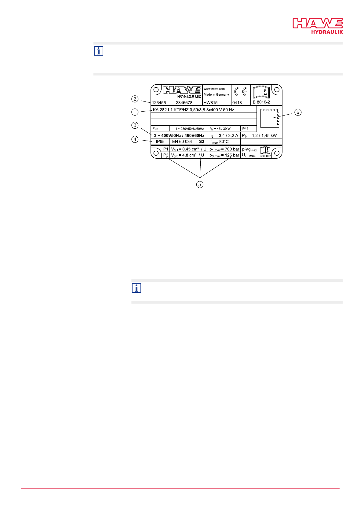
Type plate The commission number on the type plate identies the product uniquely and completely, including
all tted components.
The data are stored with the manufacturer and encoded in the DataMatrix on the type plate.
1Order coding, type coding
2– Customer order, commission number
– Production order
– Customer material number
– Date of manufacture (week XX in Year XX)
3– Motor voltage/power frequency
– Nominal current IN (50 Hz/60 Hz)
– Nominal power PN (50 Hz/60 Hz)
The actual power consumption depends on the load and can be up to 1.8 x nominal
power.
4– Protection class
– EN standard
– Operating mode
– max. temperature
– Operating capacitor only with AC motor (not included)
5– Pump port (P1 = single circuit, P3 = dual circuit)
– Geometric output volume VG (cm3/rev)
– Pump’s max. permissible operating pressure
6DataMatrix code
HAWE Hydraulik SE B 8010 - 04-2021 - 1.0 13/61
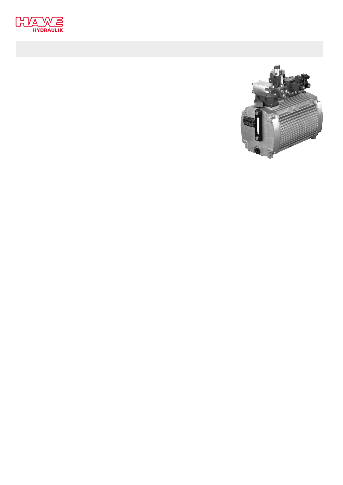
3.2 Product description
Compact hydraulic power packs are a type of hydraulic power
pack. They are characterised by a highly compact design, since
the motor shaft of the electric drive also acts as the pump shaft.
Compact hydraulic power packs are designed to supply hydraulic
circuits with hydraulic uid.
The compact hydraulic power pack type KA consists of the
tank, the integrated motor and the radial piston or gear pump
directly attached to the motor shaft. The compact design that
this achieves is a crucial advantage compared to conventional
hydraulic power packs.
The compact hydraulic power pack’s uncompromisingly module
design will enable you to quickly and easily set up a variety of
usage volumes and sizes. Compatible, ready-for-connection,
complete solutions can be assembled easily using a wide range
of connection blocks and the valve banks that can be combined
with them.
For systems with high loads, a fan that enables additional heat
dissipation can be optionally mounted on the housing. The fan is
powered by a separate motor independently of the pump motor.
KA2 and KAW2-type compact hydraulic
power pack
14/61 B 8010 - 04-2021 - 1.0 HAWE Hydraulik SE
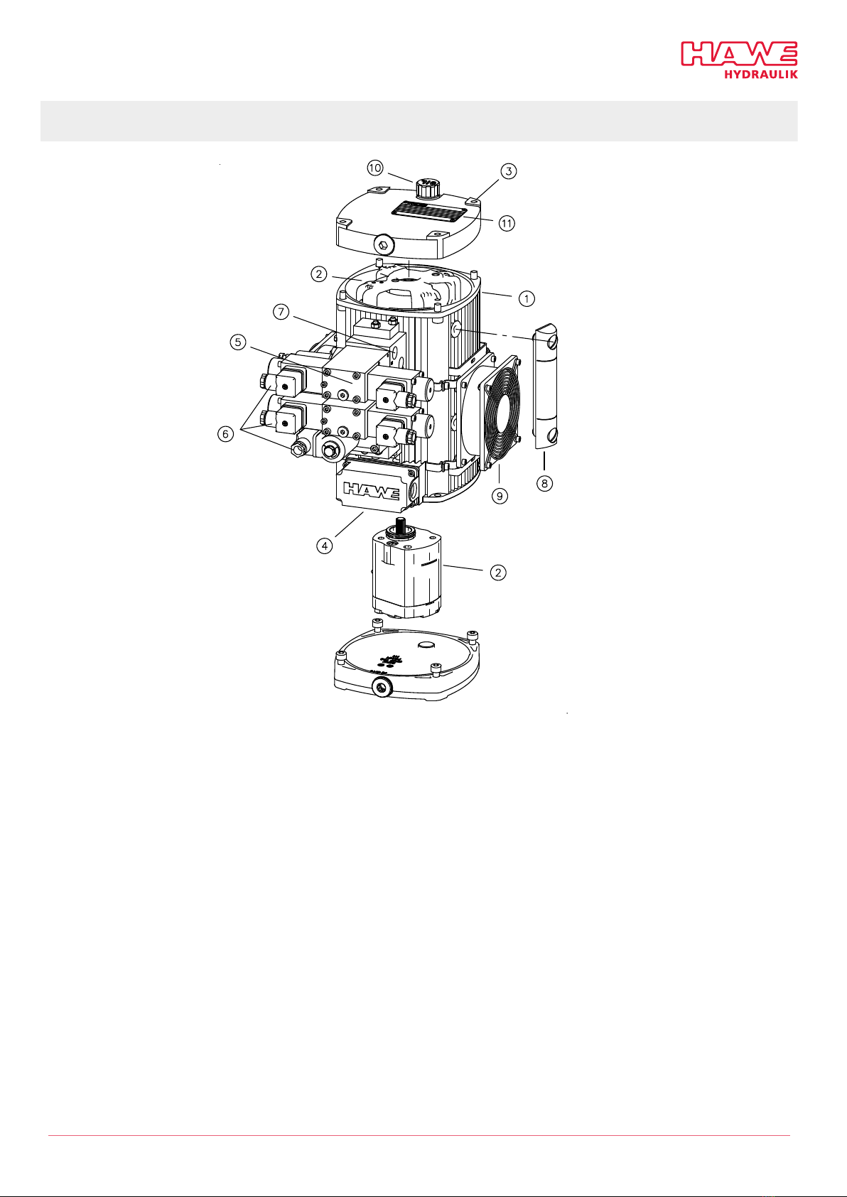
3.3 Assembly
1Hydraulic uid tank with motor
2Pump
3Fastening, e.g. for transport eyelets
Here: 2 x eye-bolts
4Terminal box for electrically connecting motor and monitoring components, e.g. temperature and level switches
5Connection block and valve bank
6Electrical connection of valves and monitoring components, e.g. pressure switches
7Hydraulic connection to consumers
8Level gauge
9External fan (optional)
10 Hydraulic uid ller neck and breather lter
11 Type plate
HAWE Hydraulik SE B 8010 - 04-2021 - 1.0 15/61

4Transport and storage
4.1 Safety instructions
WARNING
Falling, tipping and toppling heavy loads
Risk of serious injury
►Make sure that the danger zone, the area beneath suspended loads and the transport path is clear
of people.
►Wear safety shoes and protective gloves.
DAMAGE
Risk of damage from improper transport
►Only use the intended eyelets for transport.
►Make sure that belts or chains do not tear or knock components off the hydraulic power pack during
transport.
DAMAGE
Damage to the silica gel lter
►The tapped journal of the silica gel lter can shear off due to lateral forces. For transport and
assembly the silica gel lter is therefore replaced by a tapped plug in the opening.
►Transport and assemble the hydraulic power pack only with the tapped plug screwed in.
DAMAGE
Pollution from transport while lled with hydraulic uid
Hydraulic uid must be prevented from escaping into the environment.
►When transporting after prior use, drain the hydraulic uid from the tank.
►Collect cleaning, operating and lubrication uids and consumable materials in suitable containers
and dispose of them according to local regulations.
4.2 Transport
Transporting the product
Make sure that the eye-bolts are rmly attached, that there are enough of them and that they are in
the correct positions on the hydraulic power pack.
►Use the specied eye-bolts when moving the unit using belts, chains or carry handles.
►Transport methods depend on the hydraulic power pack’s weight, see "Technical data", page 56.
►Use suitable lifting gear and industrial trucks or have two people lift and carry the unit by its carry
handles.
Attachment points for
transport eye-bolts The eye-bolts are included with the product.
16/61 B 8010 - 04-2021 - 1.0 HAWE Hydraulik SE

Vertical version Pump with fan
1Eye-bolt screw-in points 1Eye-bolt screw-in points
Horizontal version
1Eye-bolt screw-in points
HAWE Hydraulik SE B 8010 - 04-2021 - 1.0 17/61

4.3 Scope of delivery
Included in scope of
delivery
■Hydraulic power pack (motor and pump in tank) with power connection (terminal box or Harting plug)
and, if applicable, suppressor
■2 transport eye-bolts on container
■Temperature switch coding T on type KAW (hydraulic power pack with alternating current)
■Breather lter, with oil dipstick on some versions
■Oil drain screw or oil drain hose
■Cap for oil ller or ller reduction with screen
Additional accessories depending on the variant chosen.
Type-specic parameters are listed on the product’s type plate, e.g.: Data on motor and pump
power.
For further technical data, refer to HAWE publication D 8010.
"Applicable documents", page 5
Not included in scope of
delivery
Electrical connection
■Line connector M12x1, 4-pin for option PM.
■Line connector M12x1, 5-pin for option KD, KS (vertical version):
(Coding KD, KS is level gauge with N/C or N/O contact switch)
Motor
■Operating capacitor for AC variant type KAW
■Motor protection circuit
Accessories for commissioning
■Damping elements for fastening
■Hydraulic uid
■Electronic controller elements for the hydraulic system
4.4 Checking the delivery
Unpacking and inspecting
1. Take out the product. Use the eye-bolts to help when doing so.
2. Check that the product is complete and check for transport damage.
■If there is any damage, refuse shipment or sign for damage when accepting it.
■Note all transport damage on the transport documents or the carrier's delivery note.
■Take photos of any product damage and submit a claim to the manufacturer immediately.
3. Dispose of the packaging in accordance with local regulations.
18/61 B 8010 - 04-2021 - 1.0 HAWE Hydraulik SE

Submit claims to:
HAWE Hydraulik SE
Einsteinring 17
85605 Aschheim
Germany
Email: inf[email protected]e
www.hawe.com
Phone: +49 (0) 89 / 37 91 00 - 1000
Claims for damage can only be accepted if submitted within the applicable claim periods. HAWE
cannot accept liability for later claims.
4.5 Storage
DAMAGE
Damage from incorrect storage
Protect the product from soiling and damage.
►Keep the product wrapped in a plastic bag when storing it to protect it from dust and constant air
circulation.
►Seal all hydraulic uid ports with caps or dummy plugs.
►Store the product in a position matching its intended mounting position, with the hydraulic uid
ller port at the top and the uid drain at the bottom.
Storage conditions Storage space ■dark
■keep away from direct sunlight and other light sources with heavy UV share
■constant temperature and humidity
■do not store close to facilities that product ozone (electric drives, high-
voltage equipment or similar)
Storage temperature +15°C to +20°C
Relative humidity 65% +/- 10%
HAWE Hydraulik SE B 8010 - 04-2021 - 1.0 19/61

5Assembly and installation
5.1 Mechanical connection
Assembly Setting up and attaching
1. Check the order coding to identify the intended mounting position.
■Vertical (type: KA...S...) or
■Horizontal (type: KA...L...)
2. Check that the support/frame possesses sufcient load capacity. This depends on the hydraulic power
pack’s weight.
3. Drill fastening holes as instructed by the mounting hole pattern.
4. Bolt into the M8 threaded holes using the recommended damping elements.
■The horizontal version can also be incorporated vertically.
■If you are installing a horizontal version vertically:
– Position with bleeder at top.
– Position the integrated pump at the bottom.
– Turn only the top housing covers, keep the extensions in their original positions.
Mounting hole pattern Horizontal version coding LVertical version coding S
Coding tank size a
-- 284
01, 1 336
02, 2 484
22, 3 684
Recommended fastening
with damping element
1Damping element #40x30/M8 (65 Shore)
20/61 B 8010 - 04-2021 - 1.0 HAWE Hydraulik SE
This manual suits for next models
8
Table of contents
Other HAWE Hydraulik Power Pack manuals

HAWE Hydraulik
HAWE Hydraulik INKA 1 User manual

HAWE Hydraulik
HAWE Hydraulik D 7969 AC Operator's manual

HAWE Hydraulik
HAWE Hydraulik A 100 User manual

HAWE Hydraulik
HAWE Hydraulik AC Series Operator's manual

HAWE Hydraulik
HAWE Hydraulik KA User manual

HAWE Hydraulik
HAWE Hydraulik HLU LE-X User manual

HAWE Hydraulik
HAWE Hydraulik HICON User manual

HAWE Hydraulik
HAWE Hydraulik HR 050 User manual


