HawkEye Electronics DepthTrax 1BX User manual

www.hawkeyeelectronics.com
This manual covers the installation and operation of both temperature and non-
temperature depth finder displays. Refer to the instructions supplied with the
transducer for transducer testing and installation. Additional resources are
available at support.norcrossmarine.com. To ensure safety and many years of
trouble-free operation of your product, please read this manual carefully before
using this product.
SAFETY INFORMATION:
•Periodically wipe the face with a dry cloth. Do not use abrasives or solvents on
this device.
•Only qualified personnel should perform repairs or servicing not covered in this
manual.
•The LCD used in the product is made of glass. Therefore, it can break when the
product is dropped or impacted.
•Keep this product away from heat sources such as radiators, heaters, stoves and
other heat generating sources. Do not store in extreme temperatures above 150°
F (65° C).
•Shade the LCD during storage. Do not expose LCD to direct sunlight for
extended periods of time.
NOTES, NOTICES, AND CAUTIONS
WARNING: Indicates a potential for property damage, personal injury or
death.
IMPORTANT: Indicates potential damage to the device and tells you how to
avoid it.
NOTICE: Indicates important information that helps you make better use of
the device and tells you how to correct a performance problem.
INFORMATION: Indicates resources to obtain the proper information to help
you make the most of your device.
INFORMATION:
Read this manual completely before attempting to use or install your
device. Visit our Customer Service Center on our website for
advanced troubleshooting and technical support.
W
ARNING
:
This depth sounder should not be used as a navigational aid to prevent
grounding, boat damage, or personal injury. Always operate the boat
at slow speeds in unfamiliar water, or if you suspect shallow water or
submerged objects.
Model No. D10D
BOAT MOUNT DIGITAL DEPTH FINDER WITH TEMPERATURE
INSTALLATION AND OPERATION MANUAL

www.hawkeyeelectronics.com
PARTS SUPPLIED IN PACKAGING
The following parts should be included with the display:
•Digital Depth Sounder Display
•White and Black Faces and Bezels (optional on some models, see
package for details)
•Thick Dash Extension Rod (optional on some models, see package for
details)
•Flush Mount Bracket and Hardware
•Display Power Harness and Waterproof Fuse Holder Attached to the Unit
N
OTICE
:
Refer to the manual supplied with the transducer for
transducer parts list.
If any items are missing or damaged, please contact our customer service
department.
SELECTING THE PROPER TRANSDUCER INSTALLATION
If you think that the included transducer is not suitable for your installation, return
to the place of purchase and exchange it for the correct transducer. You can
also visit our Customer Service Center at www.hawkeyelectronics.com to contact
us or to complete a transducer exchange request to exchange the transducer for
one that is specialized for your vessel. You may also visit
support.norcrossmarine.com to inquire about exchanging the transducer.
INSTALLING THE DISPLAY
Tools & Supplies Required for Installation
•Electric Drill
•2” Hole Saw
•Wire Connectors Suitable for Connecting the Power Wire to Your Vessel
•Wire Cutting/Crimping Tool
•Marine Sealant/Caulk
STEP 1
Installing the Display
1. Find a location on the boat that will allow clear viewing of the display. Keep
in mind that the wires for the transducer and power must reach the mounting
location.

www.hawkeyeelectronics.com
2. After finding the right location, mark a 2-inch hole. (If your boat has a pre-cut
hole in the dash panel, simply remove the hole plug and proceed to Step 5.)
IMPORTANT:
Check behind the desired cutting area for wires, switches, etc. that
may be damaged during cutting. If these obstructions are present,
use masking tape to hold them out of the way during cutting.
3. Cut out the 2-inch hole using the 2” hole saw.
4. Seal any exposed wood with a marine
sealant.
5. Insert the display from the front of the panel,
feed the wires through the bracket and install
the bracket and locking nut from the rear of
the panel. Make sure that the face of the
display is rotated upright and aligned to your
satisfaction for easy viewing from the
vessel’s helm.
NOTICE:
The display can also be surface mounted using the
Adjustable Surface Mount Bracket (P/N: ACC-DF-1000).
Please visit our website or contact us by phone for
purchase information. You must attach the extension
rod to the mounting stud on the back of the display housing before inserting
the display into the Surface Mount Bracket.
STEP 2
Installing the Face and Bezel
1. Place the face (B) over the display making
sure to line up the cut outs on the face with
the notches on the display.
2. While holding the bezel (A), place it over
the display and turn clockwise until the
bezel locks into place.
N
OTICE
:
Gold and Chrome Bezels can be purchased on our website to match
your factory dash or give your depth finder a custom look.

www.hawkeyeelectronics.com
STEP 3
Connecting of the Power Cable
The display has no ON/OFF switch. Therefore, you will need
to connect the power harness to a power source that will turn
the unit on as power is applied. The key switch or an ON/OFF
power switch will be suitable for powering the unit.
1. Connect the BLACK wire in the harness to a negative (-)
terminal or suitable ground.
2. Connect the RED wire in the harness to a positive (+) 12
Volt switchable power source (key switch, on/off switch,
terminal block, etc).
N
OTICE
:
Never use “Twist-On” or “Automotive” type
connectors. These connectors do not
form a solid
electrical connection and are more likely to corrode.
STEP 4
Testing the Display Installation
Before continuing with your installation, you
should test the unit to make sure the power
wires are properly attached.
1. Apply power to the unit by turning on the
power source that you’ve attached the red
and black wires to.
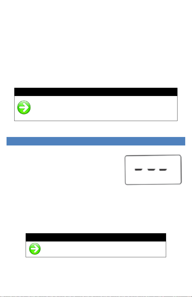
2. The buzzer should beep three times while the display
illuminates all the LCD graphics for 2 seconds. “---”
will then be shown on the LCD.
If the display operates as per #2 above, continue to the
“Basic Operation” section.
If the display does not turn ON:
1. Check the power source using a test light or DC volt
meter. Make sure there is 12 volt power where the
power harness connects to both the positive and
negative sources.
2. Check the fuse holder assembly with a test light or DC
volt meter. Connect the ground for the test meter or
light to the vessel’s negative power source.
3. Remove the fuse and check for 12 volt power at the
spring located inside the fuse housing that is

www.hawkeyeelectronics.com
connected to the vessel’s power source. If 12 volt power is present continue
to the next step. If power is not present, return to Step 1.
4. Insert the fuse and check for 12 volt power at the end of the fuse. If 12 volt
power is present continue to Step C. If power is not present, replace the
fuse.
5. Reassemble the fuse housing. Strip back a quarter of an inch of wire cover
on the display side of the fuse housing and test for 12 volt power. If 12 volt
power is present continue to Step 2.D. If power is not present, replace the
fuse housing assembly.
6. Visit our Customer Service Center at support.norcrossmarine.com for
advanced technical support.
N
OTICE
:
The fuse used in the depth finder is a .25A, 250V fuse. Do not
rely on a visual inspection of the fuse to determine if it is
functioning. If your depth sounder will not turn on, ALWAYS test
the fuse with a test light or voltage meter.
GETTING TO KNOW YOUR DIGITAL DEPTH SOUNDER
The unit’s auto-ranging, auto-sensitivity features
means that you never have to worry about
adjustments. Simply turn the power on, and
you’re ready to go. The Depth Sounder emits
sound signals that travel through water, and then
calculates the amount of time that elapsed while
the signal traveled down to the bottom and
returned back to the transducer. This time is
calculated by the microprocessor and displayed as a depth reading. Extremely
dirty water, very soft bottom, high speeds, deep water, or a combination of the
above will result in incomplete or inaccurate readings. Under these conditions
variable readings or “- - -” will be displayed.
N
OTICE
:
This depth sounder has a non-volatile memory. ALL
settings will be stored when the power is turned OFF.

www.hawkeyeelectronics.com
DISPLAY MODE SELECTION (TEMPERATURE MODELS ONLY)
The Temperature Models have 3
user selectable modes:
•Depth Sounder
•Water Temperature
•Air Temperature
To Change the Mode:
1. Press the “UP” Button to change the mode to the Right (The display will
change modes from Depth to Water Temperature to Air Temperature)
2. Press the “DOWN” Button to change the mode to the Left (The display
will change modes from Depth to Air Temperature to Water
Temperature)
NOTICE:
When a Temperature Mode is selected the Water or Air indicator will
flash on the LCD for 5 seconds while the temperature is calculated.
SHALLOW WATER ALARM
The shallow alarm function can be set for depths ranging from 3 to 200 feet and
triggers an alarm when the depth is less than the setting. You must be in the
“Depth Sounder” mode to adjust this setting.
To set the SHALLOW ALARM (upper alarm):
1. Press the "UP" key to access the shallow water
alarm setting. The icon will illuminate and the
indicator will blink.
•On depth finders with temperature,
press and hold BOTH the “UP” &
“DOWN” key for approximately 3
seconds until the ,, & icons
blink, release the keys and Press the
“UP” key once
2. Pressing the "UP" key will increase the selected value. Pressing the "DOWN"
key will reduce the value.
3. Pressing and releasing the key will change the value in 1-foot increments per
second.
4. Holding down the key will change the value in 9 foot increments per second.
5. After the desired setting is achieved, the display will return to normal
operation after 5 seconds.

www.hawkeyeelectronics.com
6. The and indicators will now be illuminated to indicate that a shallow
water alarm is set.
When triggered, the alarm sounds an audible buzzer for ten seconds while
flashing the warning LED and the and icons on the display. After 10
seconds, the audible alarm mutes and the warning LED and the and icons
continue to blink until the depth increases, or the alarm is reset. To reset the
alarm repeat steps 1 thru 5.
N
OTICE
:
Each time the Shallow Water Alarm setting is changed you must wait 5
seconds for the depth finder to return to the Normal Operation Mode in
order for the setting to be saved?
DEEP WATER ALARM
The deep alarm function can be set for depths ranging from 3 to 200 feet and
triggers an alarm when the depth is more than the setting. You must be in the
“Depth Sounder” mode to adjust this setting.
To set the DEEP ALARM (lower alarm):
1. Press the "DOWN" key to access the deep
water alarm setting. The icon will illuminate
and the indicator will blink.
•On depth finders with temperature,
press and hold BOTH the “UP” &
“DOWN” key for approximately 3
seconds until the ,, & icons blink,
release the keys and Press the
“DOWN” key once
2. Pressing the "UP" key will increase the selected value. Pressing the "DOWN"
key will reduce the value.
3. Pressing and releasing the key will change the value in 1-foot increments per
second.
4. Holding down the key will change the value in 9 foot increments per second.
5. After the desired setting is achieved, the display will return to normal
operation after 5 seconds.
6. The and indicators will now be illuminated to indicate that a deep water
alarm is set.
When triggered, the alarm sounds an audible buzzer for ten seconds while
flashing the warning LED and the and icons on the display. After 10
seconds, the audible alarm mutes and the warning LED and the and icons

www.hawkeyeelectronics.com
continue to blink until the depth increases, or the alarm is reset. To reset the
alarm repeat steps 1 thru 5.
NOTICE:
Each time the Deep Water Alarm setting is changed you must wait 5
seconds for the depth finder to return to the Normal Operation Mode in
order for the setting to be saved?
KEEL OFFSET
The Keel Offset feature is used to
adjust the depth readings
displayed by the device to
compensate for the depth of the
water required for your vessel to
operate safe (typically referred to
as your vessel’s “Draft”)
For Example: If your boat’s draft is 3 feet, the Keel Offset feature should be set
to 3 feet. The device will then subtract 3 feet from the actual depth reading and
display this figure as the depth. If the water depth is 5 feet and the Keel Offset is
set to 3 feet, the depth will be displayed as 2 feet, indicating to the operator that
there is 2 feet of safe operating water.
The maximum Keel Offset setting is 20 FT (6.1 M), and can be set in .1 (1/10th)
Feet or Meter increments. The unit will read “---” when a negative value occurs
due to the Keel Offset subtraction.
W
ARNING
:
If you are unsure of the Draft of your vessel, please consult with the
vessel’s manufacturer before setting the Keel Offset. An improper
Keel Offset setting can cause accidentally grounding of the vessel
and may cause severe damage to the vessel and its passengers.
To set the Keel Offset:
1. Press and hold the "UP" and “DOWN” keys
until the K/O indicator begins to blink
(approximately 6 seconds).
•On depth finders with Temperature
press and hold BOTH the “UP” &
“DOWN” keys until K/O blinks on the
display.
2. Release the Keys.
DRAFT

www.hawkeyeelectronics.com
3. Press the "UP” key to increase the Keel Offset value. Press the "DOWN" key
to reduce the value.
4. The display will return to the normal operation mode after five seconds if no
keys are pressed.
5. “K/O” will remain illuminated in the top left hand corner indicating that the
depth readings are adjusted to the Keel Offset setting.
NOTICE:
Each time the Keel Offset setting is changed you must wait 5 seconds
for the depth finder to return to the Normal Operation Mode in order for
the setting to be saved?
UNITS OF MEASURE
The units of measure for the depth readout and alarm functions can be set in 4
easy steps. The two settings available are Feet (FT) and Meters (M). You must
be in the “Depth Sounder” mode to adjust this setting.
To Set the Units of Measure:
1. Press and hold the "UP" and “DOWN” keys
until the current unit of measure begins to blink
(approximately 8 seconds).
•On depth finders with Temperature
press and hold BOTH the “UP” &
“DOWN” keys until FT or M blinks on
the display”
2. Release the Keys.
3. To set the units to FEET press the “UP” key.
“FT” will flash on the Display.
4. To set the units to METERS press the “DOWN” key. “M” will flash on the
Display.
5. The display will return to the normal operation mode automatically after five
seconds.
N
OTICE
:
Each time the Units of Measure is changed you must wait 5 seconds for
the depth finder to return to the Normal Operation Mode in order for the
setting to be saved?

www.hawkeyeelectronics.com
INSTALLING THE TRANSDUCER
IMPORTANT:
Install and test the display in the desired mounting location before
attempting the transducer installation.
IMPORTANT:
Refer to the instructions supplied with the transducer for transducer
testing and installation. Additional resources are available at
support.norcrossmarine.com.
NOTICE:
Any transducer supplied with our depth finders that do not have
temperature readouts can be glued in-hull. Please visit
support.norcrossmarine.com and type “Glue-In” in the search box for
step by step instructions.
TROUBLESHOOTING AND FREQUENTLY ASKED QUESTIONS
24-Hour Technical Support is available online at hawkeyeelectronics.com.
Search our online Knowledgebase for the latest troubleshooting and FAQ’s, or
post your own question for our support staff. For one-on-one support please
email customerservice@norcrossmarine.com.
INFORMATION:
If you have questions about this device please visit
our Customer Service Center on our website at
support.norcrossmarine.com
Warranty Details • Warranty Registration
Troubleshooting • Product Knowledgebase
Product Specifications • Parts & Accessories
www.hawkeyeelectronics.com
Sonar Cross Talk:
If you experience incorrect depth readings on your Digital Depth Sounder display,
but nothing on another fish finder screen on the same boat (or vice versa) then
you are experiencing sonar cross-talk interference. The only real solution is to
move the transducers further away from each other. This can help keep the
transducer cones from intersecting, but because cones get wider as the depth

www.hawkeyeelectronics.com
increases, the problem can not usually be completely solved by position only.
Changing one of the sounders to another model that runs on a different
frequency will solve the problem.
Using A Non-Standard Transducer:
You may be able to use a transducer that is currently installed in your watercraft
or a specialized transducer. You need to be sure that the transducer runs on 200
Khz and is able to put out 250 watts of transmitting power. If you are unsure of
the specifications, please contact the manufacturer. If you need to attach a non-
standard transducer to the Digital Depth Sounder display, order part # ACC-DF-
1147 from our website hawkeyeelectronics.com. Strip back the rubber cable
cover 1” (28 mm) exposing the internal wires on your transducer. Using a
soldering iron, solder the wires to the corresponding wires on your transducer.
Using electrical tape, or heat shrink tubing make certain that the soldered
connections are completely sealed and protected against accidental electrical
interference and corrosion. Cutting the plug off the Digital Depth Sounder display
will void the warranty.
Poor Performance:
If you are not happy with the performance of your depth sounder, please visit our
support center at support.norcrossmarine.com technical support. Rest assured
that this depth sounder is engineered to the highest standards and is part of the
best selling family of depth sounders in the world. It is highly likely that your
dissatisfaction is due to improper installation and/or setup and our technical
support resources can get your system working properly.
REPLACEMENT PARTS
Individual components are not available for sale on our website. If you need
replacement parts, please email our customer service department.
WARRANTY
This device is covered by a 2 Year Limited Warranty. To be eligible for warranty
coverage, you must register your product within 15 days of purchase. Visit our
website for warranty details and to register.
•To Activate Your Warranty:
•Read and print out a copy of the warranty details for your records.
•Complete the registration form our website.
•Make a copy of your original purchase receipt and staple it to this manual.
(You will need to present it in the rare occurrence that you need to send
your product in for service.)
•Complete the information below and store this manual in a safe place.
(You can print additional copies of this manual from our website.)

www.hawkeyeelectronics.com
INFORMATION:
To aid in maintenance and service, record the following:
Date of Purchase: ___________________
Place of Purchase: _____________________________________
Date of Online Warranty Registration: _____________________
Production Date Code: ________ (3 digit code located on the device housing)
LEGAL
I
NFORMATION
:
Made in China. Tested to comply with FCC, CE & ROSH standards if
applicable. Visit our website for compliance and warranty information. All
Specifications and Prices Subject to Change Without Notice.
NorCross Marine Products, Inc
support.norcrossmarine.com
support@norcrossmarine.com
www.norcrossmarine.com v4315
W
ARNING
:
© 2018 NorCross Marine Products Inc., All Rights Reserved. ALL
unauthorized copying of the content of this document without the
expressed written consent of NorCross Marine Products, Inc is
strictly forbidden.
Table of contents
Popular Marine Equipment manuals by other brands

MAP-Tech
MAP-Tech MAP Pilot installation manual

E2S
E2S IS-D105 instruction manual

Kohler
Kohler 5EOZ manual

Paradox Marine
Paradox Marine GOST Immobilizer installation guide

DIGITAL YACHT
DIGITAL YACHT ZDIGAQU100N Installation & quick start guide

Millennium Marine
Millennium Marine D-200-00 Side Kick instructions