Haws 9035 Guide

12/19 Model 9035 Page 2 of 26
IMPORTANT
Read this installation manual completely to ensure proper installation, then file it with the owner or
maintenance department. Compliance and conformity to drain requirements and other local codes
and ordinances is the responsibility of the installer.
Separate parts from packaging and make sure all parts are accounted for before discarding any
packaging material. If any parts are missing, do not begin installation until missing parts are
obtained.
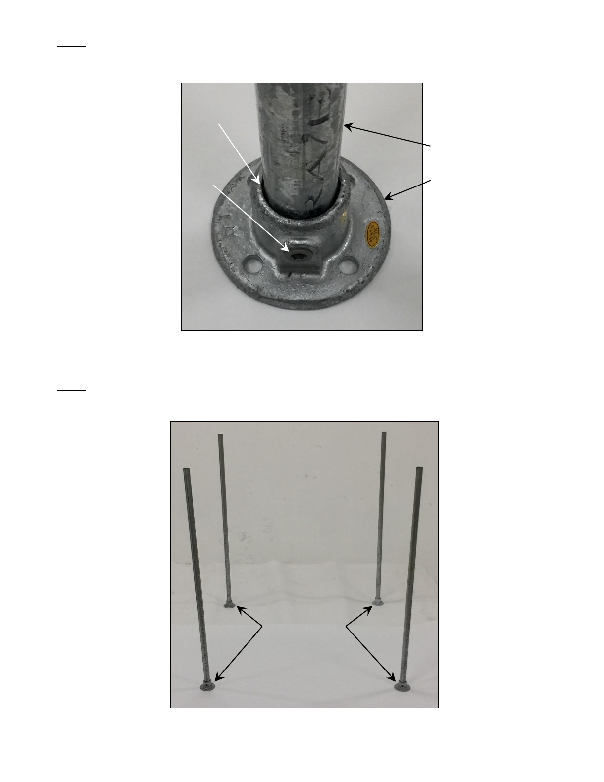
This unit must be fastened to the floor. It is recommended that this unit be installed in an area that
has a hard surface that can accommodate floor fasteners.
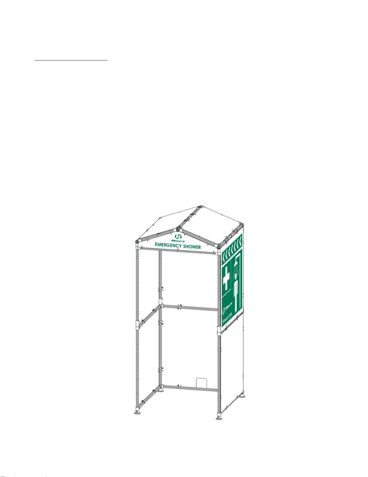
DESCRIPTION OF PRODUCT
Haws Corporation Model 9035 Shower Shelter (with Privacy Curtain option).
Not part of any Certified model. Not Certified on its own.
Haws Model 9035 can be installed indoors or outdoors. Its usage intention is weather and privacy
protection.
SHIPPING, HANDLING AND STORAGE
Model
Description
Dimensions
W x L x H
(Shipping)
Weight
(Crated)
9035
Shower Shelter
48” X 52” x 10”
375 lbs.
Recommended Equipment, Materials, and Supplies to be provided by Installer:
•Existing slab on grade. The installer shall verify that the following minimum requirements of the
existing slab-on-grade are satisfied.
oAllowable Soil Bearing Pressure: 1500 psf
oSlab-on-grade minimum thickness: 6 inches
oCompressive Strength of slab, f’c: 3000 psi
oAdequate footprint area (minimum 6’ x 6’ recommended)
oAdequate vertical space (minimum 14.5 ft. recommended, 13 ft. required)
•Recommended anchors (Not Included, customer to determine anchor suitability):
High strength adhesive anchors (ICC-ES Report ESR-3187): Hilti HIT-HY 200 Safe Set epoxy
adhesive anchorage system and Hilti hollow drill bit system with 5/8” diameter Hilti HIT-Z Rod,
2 ASTM F844 flat washers, and ASTM A563 Grade A nuts. Floor Flanges have four (4) 5/16”
diameter clearance holes (16 total).
Hilti specifies 3-3/4” minimum embedment depth per HIT-Z specifications. A forklift capable of
safely lifting and maneuvering this product should be utilized to transport the unit from truck to
site.

12/19 Model 9035 Page 3 of 26
Tools and Supplies (Not Supplied)
•Two (2) Qualified Personnel
•Two (2) Step Ladder
•One (1) Set of Cutters (for Plastic Straps).
•1/4” Hex Keys (for Pipe Fitting Set Screws).
•7/16” Socket and Ratchet, or Power Drill (for Panels).
•7/16” Box End Wrench or adjustable Crescent Wrench (for Panels).
•Rubber Mallet or Dead Blow Hammer
•Felt Tip Marker
•Appropriate personal protective equipment (PPE) including safety glasses and work gloves.
Storage: Unit should be stored in a clean, dry place until ready for installation.
PALLET CONTENTS
NOTE: Confirm all components listed for the Model 9035 are present before assembly. See Table 1.
ITEM NO.
PART DESCRIPTION
QTY
1*
FLOOR FLANGE FITTINGS
4
2*
SHORT TEE FITTINGS
12
3*
90º SHORT ELBOW FITTINGS
4
4*
STRAIGHT COUPLING FITTINGS
4
5*
SHORT SWIVEL TEE-PAIR FITTINGS
6
6
1.00” X 51.00”SCHED 40 GALV STEEL PIPES
4
7
1.00” X 49.12” SCHED 40 GALV STEEL PIPES
3
8
1.00” X 46.12” SCHED 40 GALV STEEL PIPES
8
9
1.00” X 45.25” SCHED 40 GALV STEEL PIPES
4
10
1.00” X 22.25” SCHED 40 GALV STEEL PIPES
4
11
1.00” X 23.75” SCHED 40 GALV STEEL PIPES
2
12
PLAIN SIDE PANELS
2
13
SLOTTED REAR PANELS
2
14
LEFT SIDE PANEL W/ ARTWORK
1
15
RIGHT SIDE PANEL W/ ARTWORK
1
16
PLAIN ROOF PANELS
2
17
TRIANGULAR ROOF PANELS W/ ARTWORK
2
18*
1/4-20 UNC-2A X 1.00”SST HEX HEAD SCREWS
88
19*
1/4-20 UNC-2B SST NYLON SELF-LOCKING HEX NUTS
88
20*
¼” SST FLAT WASHERS
88
21*
1.31”ID STEEL LOOP CLAMPS
88
22*
1.00” PIPE END CAPS
6
23*
JIFFY BAG
1
24*
9035 O&M DRAWING
1
25
14 3/4” X 8 3/4”X 2” CARTON (PN 0001609490.1)
5
* Items are packed into (5) Cartons, Item 25, as shown. (See Figure A.)
SHIPPING CONTENTS / TABLE 1

12/19 Model 9035 Page 4 of 26
ON-SITE DELIVERY, HANDLING AND PACKAGE DISASSEMBLY
Transport the palletized Model 9035 unit to the installation point via forklift, ensuring the forks are fully
inserted through the shipping pallet.
The installation area should be a level surface capable of supporting up to 1,000 lbs. spread across a
5 foot by 5 foot area. Concrete flooring is preferred.
Confirm there is suitable available vertical space where the unit can be installed. The unit requires a
minimum of 10 feet vertical space for assembly and installation.
Cut the two (2) plastic bands that strap the components into the wooden pallet. (See Figure A.)
Unwrap the bundled panel package and carefully set the panels aside for installation.
FIGURE A
Open and inspect the contents of all five (5) cartons. Compare the carton contents against the items listed in
Table 1.
FIGURE B (Carton Contents)
4X Item 3
12X Item 2
1X Item 25
4X Item 4
6X Item 5
1X Item 25
4X Item 1
6X Item 22
1X Item 25
88X Item 18
88X Item 19
88X Item 20
1X Item 23
1X Item 24
1X Item 25
88X Item 21
1X Item 25
2X Plastic
Shipping Straps
1X Bundled
Panel Package

12/19 Model 9035 Page 5 of 26
MODEL 9035 GENERAL ASSEMBLY NOTES
Unless otherwise specified: All PIPES must be fully engaged into floor flanges and fittings. On parts where there
are no internal stopping features, pipe ends will terminate at intersecting pipe surfaces or where they run out.
Full engagement of the pipes is critical to the overall size and shape of the unit and to the correct alignment of
all fittings, loop clamps and panels.
All FITTINGS must be oriented such that their mounting screw bosses (Hex Set Screws are included with all
fittings) face toward the inside of the unit. This allows the shelter cover panels to rest close to the frame and to
mate flush with the panel mounting loop clamps. Mounting screws in the 90º Short Elbows should face upward
for best tool access.
All SET SCREWS must be fastened in place using thread-locker (not supplied). However, it may become
necessary to re-align fittings and pipes prior to locking the set screws. Apply thread-locker sparingly at first, to
allow for final adjustment and, when final alignment is ascertained, sufficiently coat all screws and lock in place.
9035 SHOWER SHELTER / FINAL ASSEMBLY PREVIEW
FIGURE 1

12/19 Model 9035 Page 6 of 26
The following section illustrates the assembly of the Bottom Level Frame. All of the parts necessary to build this
stage are indicated in Figure 2 and assembled as described in Steps 1 thru 11.
FIGURE 2 / Bottom Level Frame Assembly
2X Short Tees
2X Floor Flanges
2X 46.12” Pipes
2X Floor Flanges
1X 46.12” Pipe
3X 46.12” Pipe
4X 51.00” Pipes
1X 46.12” Pipe
2X 90º Short Elbows
2X 90º Short Elbows
2X Short Tees
2X Short Tees

12/19 Model 9035 Page 7 of 26
Step 1: Insert four (4) 51.00" Pipes into four (4) Floor Flanges such that the pipes seat fully into the bottom of
the floor flange cups. (See Figure 3.) Tighten the floor flange side set screws with a 1/4” hex key.
FIGURE 3
Step 2: Stand the four (4) flange / pipe assemblies from Step 1 on a flat horizontal surface and position them
approximately 48” apart. (See Figure 4.)
FIGURE 4
4X 51.00” Pipe
4X Floor Flange
(Floor Flange Cup)
(Floor Flange
Set Screw)
4X Flange / Pipe
Assemblies
Left
Side
Right
Side

12/19 Model 9035 Page 8 of 26
Step 3: Install one (1) each Short Tee onto the two front side (vertical) pipes, ensuring that the set screws face
inwardly. (See Figure 4A.)
Step 4: Install one (1) each 90 º Short Elbow onto the two rear side (vertical) pipes, ensuring that the 90º elbow
angles face inwardly and the set screws face upward. (See Figure 4A.) (Note: Prior to tightening the tee and
elbow set screws, rotate the fittings such that all four of the floor flanges’mounting holes are un-covered by the
tee and elbow bodies. This allows tool access to the floor mounting hardware. (See Figures 4A & 4B.)
Left Front FIGURE 4A Right Front
Left Rear FIGURE 4B Right Rear
2X Short Tees
Flange Mounting Holes
Flange Floor
Mounting Holes
2X 90º Short Elbows

12/19 Model 9035 Page 9 of 26
Step 5: Fully insert two (2) 46.12” Pipes into the open ends of the left and right side fittings. (See Figure 5.)
Tighten the tees and elbows set screws.
Step 6: Fully insert one (1) 46.12" pipe into the open ends of the rear side fittings. (See Figure 5.) Tighten the
elbow set screws.
FIGURE 5
Step 7: Measure and mark 1 3/4" down from the top of the four 51.00” pipes, with a felt tip marking pen.
(See Figure 6.)
FIGURE 6
Right Rear
Right Front
Left Rear
Left Front
3X 46.12” Pipes
4X 51.00” Pipes
1 3/4” From
Top of Pipes

12/19 Model 9035 Page 10 of 26
Step 8:Install two (2) Short Tees onto the front side (vertical) pipes and align the thru-hole edges with the
marks from Step 6. (See Figure 6A.) Rotate the tees such that the setscrews face inward. (See Figure 6A.)
Tighten the tee set screws.
Step 9:Install two (2) Short 90º Elbows onto the rear side pipes and align the thru-hole edges with the marks
from Step 6. (See Figure 6B.) Rotate the elbows such that the 90º angles face inward. (See Figure 6A.)
Tighten the elbow set screws.
FIGURE 6A / Left Front Position FIGURE 6B / Right Rear Position
Step 10:Fully insert two (2) 46.12” Pipes into the open ends of the left and right fittings. (See Figure 7.)
(Loosen and re-align the fittings as necessary.) Tighten the tee and elbow set screws.
Step 11:Fully insert one (1) 46.12" Pipe into the open ends of the rear fittings. (See Figure 7.) (Loosen and
re-align the fittings as necessary.) Tighten the elbow set screws
FIGURE 7
1 3/4" Mark
Thru Hole Edge
1 3/4" Mark
Thru Hole Edge
3X 46.12” Pipes
Right Rear
Rear Side
Right Side
Left Side

12/19 Model 9035 Page 11 of 26
The following section illustrates the assembly of the Middle Level Frame. All of the parts necessary to build this
stage are indicated in Figure 8 and assembled as described in Steps 12 thru 17.
FIGURE 8 / Middle Level Frame Assembly
2X 46.12” Pipes
4X Short Tees
4X 45.25" Pipes
4X Straight
Couplings
4X Swivel Tee-Pair
(Bottom Halves)
(Bottom Level
Frame Assembly)

12/19 Model 9035 Page 12 of 26
Step 12: Insert one (1) each of the Straight Couplings onto the protruding 1 3/4" section of the 51.00" pipes
from Step 7. (See Figure 9. See Figures 9A & 9B for orientation of the fittings.) Tighten the bottom set screws.
FIGURE 9
(Figure 9A / Right Rear Position depicts the orientation of the rear side straight couplings. Both fittings are
rotated inward, approximately 45º, between the elbow pipe cups to allow access to the elbows’ top-mounted set
screws. Figure 9B / Right Front Position depicts the orientation of the front side straight couplings. Both fittings
face the same direction as the short tees below them –inward - allowing clear access to all set screws.
FIGURE 9A / Right Rear Position FIGURE 9B / Right Front Position
2X Straight Couplings
(Bottom Level
Frame Assembly)
2X Rear Side
Straight Couplings
Set Screws
Elbow
2X Front Side
Straight Couplings
Set Screws
Tee

12/19 Model 9035 Page 13 of 26
Step 13: Fully insert four (4) 45.25" pipes into the straight couplings from Step 12 Ensuring that the pipe . (See
Figure 10.) Tighten the straight coupling set screws.
FIGURE 10
Step 14: Install four (4) Short Tee fittings onto the 45.25” vertical pipes from Step 13, approximately where
shown. (See Figure 10.) Ensure that all of the set screws face inward. Do not fully tighten.
FIGURE 11
Step 15: Install one half of four (4) Short Swivel Tee-Pairs onto the tops of the 45.25” vertical pipes. Note: Set
screws to be pointed inward (See Figures 12, 12A & 12B for orientation). Ensure that the axes of the pivot holes
are oriented such they run parallel to the sides of the unit. Tighten the swivel tee pipe cup set screws.
FIGURE 12 FIGURE 12A FIGURE 12B
(2X Left Side) (2X Right Side)
4X 45.25” Pipes
Straight
Couplings
45.25” Pipes
4X Short Tees
4X Swivel Tees
(Swivel Tee-Pair
Bottom Halves)
45.25” Pipes

12/19 Model 9035 Page 14 of 26
Step 16: Loosen the tee set screws from Step 15 and raise the tees flush to the bottoms of the swivel tee-pairs;
(See Figures 13, 13A & 13B.) Align the tees such that the tee pipe cups run parallel to the swivel tee-pair set
screws. Re-tighten the tee set screws.
FIGURE 13 FIGURE 13A FIGURE 13B
(2X Left Side) (2X Right Side)
Step 17: Gently pull the front and rear vertical pipes apart and insert two (2) 49.12” Pipes, horizontally, into the
tee pipe cups. (See Figure14.) (It may be necessary to loosen the vertical pipe tees in order to properly align the
horizontal pipes and tees; If so, do this, re-tighten them, and then tighten the tee pipe cup set screws.)
FIGURE 14
-----------------------------------------------------------------------------------------------------------------------------------------------------
Tees
4X Swivel Tees
(Swivel Tee-Pair
Bottom Halves)
2X 46.12” Pipes
Tees
Tees

12/19 Model 9035 Page 15 of 26
The following section illustrates the assembly of the Top-Level Frame. All of the parts necessary to build this
stage are indicated in Figure 15 and assembled as described in Steps 18 thru 28.
FIGURE 15 / Top Level Frame Assembly
2X Roof End Supports
(Sub-Assemblies)
(Bottom Level
Frame Assembly)
(Middle Level
Frame Assembly)
3X 49.12” Pipes
Roof Center Support
(Sub-Assembly)
2X Roof End Supports
(Sub-Assemblies)
Roof Center Support
(Sub-Assembly)

12/19 Model 9035 Page 16 of 26
Step 18: Create four (4) Roof End Support assemblies: Fully insert four (4) 22.25" Pipes into the pipe cup end of
eight (8) Short Swivel Tee-Pair fitting halves. Orient the swivel tees such that the set screws at both ends are
facing upwards and perpendicular to the ground. (See Figure 16.) Tighten the swivel tee set screws.
Step 19: Create two (2) Roof Center Support assemblies: Fully insert two (2) 23.75" Pipes into the pipe cup
ends of four (4) Short Tee fittings allowing for pass-through of adjoining pipe. Orient the tees such that the set
screws at both ends are facing upwards and perpendicular to the ground. (See Figure 16.) Tighten the tee set
screws.
FIGURE 16
Step 20: Slide one (1) 49.12” Pipe through the right-side swivel tee thru hole at the rear side of the unit. Push
the pipe two feet into the thru hole and install - with the set screws facing outward - one (1) Roof End Support
and one (1) Roof Center Support, onto the 49.12” pipe. Slide the 49.12” pipe to the front and through the right-
side swivel tee thru hole. (See Figure17A.) Flush the 49.12” pipe to the outer surface of the rear swivel tee and
tighten the swivel tee thru hole set screw only. (See Figure17B.)
FIGURE 17A FIGURE 17B
4X Roof End Supports
(Sub-Assemblies)
2X Roof Center Support
(Sub-Assemblies)
2X Short Tees
2X Short Tees
4X Short Swivel Tees
4X 22.25” Pipes
4X 23.75” Pipes
Roof Center
Support
Roof End
Support
49.12” Pipe
Rear Side
of Unit
Right Side
of Unit
Rear Side Swivel Tee
Thru Hole & Setscrew
Right Side
of Unit

12/19 Model 9035 Page 17 of 26
Step 21: Slide one (1) 49.12” Pipe through the left side swivel tee thru hole at the front side of the unit. Push
the pipe two feet into the thru hole and install - with the set screws facing outward - one (1) Roof End Support
and one (1) Roof Center Support, onto the 49.12”pipe. Slide the 49.12” pipe to the rear and through the left-side
swivel tee thru hole. Flush the pipe to the outer surface of the front swivel tee and tighten the set screw at the
front of the unit only (See Figures 18A & 18B.)
FIGURE 18A FIGURE 18B
Step 22:Fasten the loose ends of the 49.12” pipes at the front and rear of the unit by pushing the 49.12” pipes
into the swivel tee thru holes such that one inch of pipe protrudes past the swivel tee thru hole. (See Figure 19.)
Tighten the tee-pair setscrews at the thru holes.
FIGURE 19 (2 Places)
Front Side
of Unit
49.12” Pipe
Roof End
Support
Roof Center
Support
Left Side
of Unit
Left Side
of Unit
Front Side Swivel Tee
Thru Hole & Setscrew
Loose End
1” Protrusion -
49.12” Pipe
Swivel Tee
(Swivel Tee-Pair
Bottom Half)
Swivel Tee
Thru Hole

12/19 Model 9035 Page 18 of 26
Step 23:Install one (1) Roof End Support onto the exposed section of pipe at the rear of the unit. Slide the right
side roof end support to the rear side and rotate both roof end supports such that the swivel tee thru holes’ axes
are roughly aligned and the swivel tee surfaces mate. (See Figure 20A.) Tighten the swivel tee set screws at the
49.12” pipes.
FIGURE 20A
(Figure 20B shows a wider view of how the unit should look when the rear side roof support ends are properly
installed and arranged,)
FIGURE 20B
Step 24: Measure 24 9/16" from the outer surfaces of the left rear & right rear swivel tee thru holes, along the
center of each 49 .12” pipe, and mark a line on each pipe with a felt-tip marking pen. (See Figures 21A & 21B.)
(These marks represent the mid-points of the 49.12” pipes.)
FIGURE 21A FIGURE 21B
Step 25: Slide the two Roof Center Supports along the 49.12” pipes such that the rear edge of one tee and the
front edge of the other tee align with the marked lines from Step 24. Rotate the roof center supports such that
the thru holes’ axes are roughly aligned and the swivel tees mate. (See Figure 22.) Tighten the swivel tee set
screws at the 49.12” pipes.
FIGURE 22
2X Swivel Tee
Thru Holes
Roof End Support
Exposed End of
49.12” Pipe
2X Swivel Tee
Thru Holes
2X Roof End
Supports
Rear Side
Mark at 24 9/16”
from Rear Side
Rear Side
Mark at 24 9/16”
from Rear Side
Roof Center Support
2X Swivel Tee Thru Holes
Roof Center Support

12/19 Model 9035 Page 19 of 26
Step 26: Install one (1) Roof End Support onto the exposed section of pipe at the right front corner of the unit.
Slide the left side roof end support to the front of the unit. Rotate both roof end supports such that the swivel tee
thru holes’ axes are roughly aligned and the swivel tees mate. (See Figure 23.) Tighten the swivel tee set
screws at the 49.12” pipes.
FIGURE 23
Step 27: Insert one (1) 49.12” Pipe into the end support swivel tee thru holes at the roof apex. (Note: It may be
necessary to loosen some swivel tee setscrews and tee set screws to allow the pipe to slide through freely.)
Continue to slide the pipe thru the center support swivel tee thru holes moving rearward - loosening and aligning
as needed - until the pipe slides easily through the front end and center support tees. (See Figure 24.)
FIGURE 24
Step 28: Slide the 49.12” pipe to the rear and through the end support swivel tee thru holes. (See Figure 25.)
Tighten the setscrews at the roof-top 49.12” pipe. (Re-tighten any loosened set screws.)
FIGURE 25
49.12” Pipe
End Support
Thru Holes
49.12” Pipe
(Exposed End)
Roof End Support
2X Swivel Tee Thru Holes
End Support
Thru Holes
1X 49.12” Pipe
Center Support
Thru Holes

12/19 Model 9035 Page 20 of 26
The following section illustrates the installation of the Shelter Panels. All of the parts necessary to build this
stage are indicated in Figure 26 and assembled as described in Steps 28 thru 32.
FIGURE 26
(CAUTION: At this stage it is likely that some of the fittings’ setscrews are not fully tightened, and that
some fittings and pipes are not-aligned as intended. Therefore, it is highly recommended that steps be
taken to square-up, re-tighten & thread-lock the setscrews prior to proceeding with the panel
installation.
2X Plain Roof Panels
2X Triangular Panels
(Rear Panel not shown)
1X Right Side
Printed Panel
1X Left Side
Printed Panel
1X Slotted Rear Panel
2X Plain Side Panels
Table of contents
Popular Shelter manuals by other brands

NBB
NBB SR8064-F Assembly instructions

ShelterLogic
ShelterLogic Shed-in-a-Box 70401 Assembly instructions

Hardlife Utility
Hardlife Utility C2020H Assembly manual

Storage Canopy
Storage Canopy C2620R Assembly instructions

Vikre Handel AS
Vikre Handel AS SS305018 Assembly instructions

KWIK GOAL
KWIK GOAL 9B51 Assembly instructions

Mytee
Mytee 3340 Assembly instructions

NORMARC
NORMARC Rapala CRUZER M1 Operator's manual

Shelters4Less
Shelters4Less SR1556 Assembly instructions

IAE
IAE FLAT ROOF SMOKING SHELTER Assembly & Maintenance Manual

No Butts Bin
No Butts Bin SR1554 Assembly instructions

SURF & TURF
SURF & TURF Robusta Assembly instructions