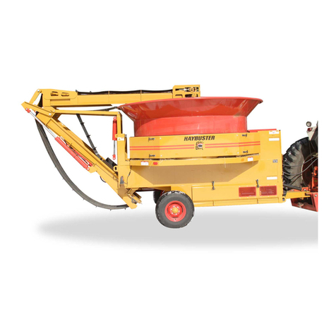
Haybuster 77 Parts list manual

PO BOX 1940, JAMESTOWN, ND 58402-1940
JUNE 2014 0500117
77/107 DRILLS
107 DRILL - S.N. CJ 4427 & UP
77 DRILL - S.N. CJ 50177 & UP
Operating Instructions
and Parts Reference

A Tradition of Innovation Since 1966

DuraTech Industries International Inc. (DuraTech Industries) has made every effort to assure that
this manual completely and accurately describes the operation and maintenance of the 77/107
DRILL™ as of the date of publication. DuraTech Industries reserves the right to make updates to
the machine from time to time. Even in the event of such updates, you should still find this manual
to be appropriate for the safe operation and maintenance of your unit.
This manual, as well as materials provided by component suppliers to DuraTech Industries are all
considered to be part of the information package. Every operator is required to read and understand
these manuals, and they should be located within easy access for periodic review.
and are registered trademarks of Duratech Industries
International, Inc. 77 DRILL and 107 DRILL are trademarks of Duratech Industries International,
Inc.
77/107 DRILLS
107 DRILL - S.N. CJ 4427 & UP
77 DRILL - S.N. CJ 50177 & UP
Operating Instructions
and Parts Reference

A Tradition of Innovation Since 1966

i77/107 DRILLS OPERATING INSTRUCTIONS
Foreword
All personnel must read and understand before operating unit
•Foreword and Section 1, important safety information.
•Section 2, ”Dealer Preparation,” to verify that the machine has been prepared
for use.
•Section 3, “Introduction,” which explain normal operation of the machine.
•Section 4.1, “Operating Instructions” Pre-Operation Inspection Check List.
Appropriate use of the unit
The 77/107 Grain Drill is designed to seed No-Till, Minimum Till, or conventionally
tilled fields. The two compartment hopper offers the flexibility of seeding with
fertilizer, seeding alone, or planting two different seeds.
Operator protection
As with all machinery, care needs to be taken by the operator in order to insure the
safety of the operator and those in the surrounding area.
WARNING: Operators and those observing the operation of the 77/107
GRAIN DRILLS are required to wear head, eye, and ear protection. No loose
clothing is allowed.

ii 77/107 DRILLS OPERATING INSTRUCTIONS
TABLE OF CONTENTS
Part 1: Operating Instructions ...........................................
Introduction ................................................................................ 2
Purpose ....................................................................................... 2
Section 1: Safety ....................................................................... 3
1.1 Safety-Alert Symbols ........................................................................................ 3
1.2 Operator - Personal Equipment ........................................................................ 5
1.3 Machine Safety Labels ..................................................................................... 6
1.4 Shielding ............................................................................................................ 8
1.5 Personal Equipment .......................................................................................... 8
1.6 Safety Review................................................................................................... 8
Section 2: Dealer Preparation ................................................ 12
2.1 Gauge Wheel Attachment ............................................................................... 12
2.2 False Bottom Attachment (107 Only) ............................................................. 14
2.3 Drill Legume Box Attachment ........................................................................ 16
2.4 Legume Hopper Shipping Kit (Optional)......................................................... 18
Section 3: Introduction ............................................................ 19
3.1 Ordering Parts................................................................................................. 19
3.2 Serial Number Decal....................................................................................... 20
3.3 About Your 77/107 Grain Drill ......................................................................... 20
Section 4: Operating Instructions ........................................... 21
4.1 Operating Instructions ..................................................................................... 21
4.2 Grain Drill Setup.............................................................................................. 22
4.3 Pressure Spring Adjustment
4.4 Press Wheel Adjustment ................................................................................. 23
4.5 Haybuster 77/107 Drill Opener ....................................................................... 24
4.6 Feed Wheel Space Adjustment ....................................................................... 25
4.7 Drill Cleanout Slides ........................................................................................ 26
4.8 Calibration Pointer Adjustment........................................................................ 27
4.9 Setting And Checking Feed Rate .................................................................... 28
4.10 Checking Feed Rate...................................................................................... 29
4.11 Drilling With The Grain Drill.......................................................................... 35
4.12 Suggestions.................................................................................................... 37
4.13 Rear Wheel Swivel And Adjustment............................................................. 37
4.14 Transporting The Grain Drill ......................................................................... 37
4.15 Preparing For Storage .................................................................................. 39
4.16 Removing From Storage ............................................................................... 39
Section 5: Grass Seeding Reference ...................................... 41
5.1 Grass Seeding Attachments ............................................................................ 41

iii77/107 DRILLS OPERATING INSTRUCTIONS
TABLE OF CONTENTS
5.2 Legume Box Applications ............................................................................... 42
5.3 Single Agitator Applications ............................................................................ 42
5.4 Special Instructions For Warm Season Grasses ............................................. 42
5.5 Pure Live Seed Calculations ........................................................................... 43
Section 6: Lubrication .............................................................. 45
APPENDIX A: WARRANTY ....................................................... 48
APPENDIX B: SPECIFICATIONS .............................................. 49
Part 2: Parts Reference .................................................. 45
77 MAIN FRAME ASSEMBLY........................................................................... 52
107 MAIN FRAME ASSEMBLY ......................................................................... 54
77 DRIVE ASSEMBLY ........................................................................................ 58
77 DRIVE WHEEL ASSEMBLY ......................................................................... 60
107 DRIVE ASSEMBLY ...................................................................................... 62
TANK END DRIVE (77 & 107) .......................................................................... 64
RUN ASSEMBLY (77 & 107) .............................................................................. 66
77 TANK ASSEMBLY (DETAIL A) .................................................................... 68
77 TANK ASSEMBLY (DETAIL B) .................................................................... 70
77 TANK ASSEMBLY - BACK ........................................................................... 72
107 TANK ASSEMBLY........................................................................................ 74
SEED & FERTILIZER SETTING ASSEMBLY .................................................. 76
SCRAPER ASSEMBLY ....................................................................................... 77
COULTER & DISK ASSEMBLY ........................................................................ 78
PRESS WHEEL ASSEMBLY ............................................................................... 79
DEPTH BAND INSTALLATION ....................................................................... 81
HUB ASSEMBLY ................................................................................................. 82
HUB FORK ASSEMBLY ..................................................................................... 84
FRONT STABILIZER OPTION (107 ONLY) .................................................... 85
REAR STABILIZER OPTION (107 ONLY)....................................................... 86
TOW HITCH (107 ONLY) ................................................................................... 88
BALLAST BRACKET (77 & 107) ...................................................................... 89
HITCH LIFT (107 ONLY) .................................................................................... 90
DRILL SINGLE HITCH (77 & 107) .................................................................... 92
SWIVEL HITCH (77 & 107) ................................................................................ 93
2 DRILL HITCH (107 ONLY).............................................................................. 94
3-4 DRILL HITCH (107 ONLY) .......................................................................... 96
SINGLE DRILL & 2 DRILL HYDRAULICS..................................................... 97
3 DRILL HYDRAULICS (107 ONLY)................................................................ 98
4 DRILL HYDRAULICS (107 ONLY)................................................................ 99
DECALS.............................................................................................................. 100

iv 77/107 DRILLS OPERATING INSTRUCTIONS
TABLE OF CONTENTS
DECAL LOCATIONS ........................................................................................ 102
77 LEGUME BOX OPTION .............................................................................. 104
107 LEGUME BOX OPTION ............................................................................ 106
SEED INDEX ASSEMBLY LEGUME BOX (DETAIL C) .............................. 108
CUP ASSEMBLY LEGUME BOX (DETAIL D).............................................. 109
LEGUME DROP TUBE ASSEMBLY ............................................................... 110
LEGUME BOX MOUNTING BRACKET (77 & 107) ..................................... 112
ACRE COUNTER (OPTION) (77 & 107) ........................................................ 113
FALSE BOTTOM OPTION (107 ONLY) ......................................................... 114
GAUGE WHEELS OPTION (107 ONLY) ........................................................ 116
DRILL LIGHT KIT & SMV (77 & 107)............................................................ 118
NATIVE GRASS KIT
PARTS REFERENCE & INSTALLATION INSTRUCTIONS ........................ 121
77 NATIVE GRASS KIT OPTION - ADDITIONAL AGITATOR SHAFTS .. 122
107 NATIVE GRASS KIT - ADDITIONAL AGITATOR SHAFTS................. 124
107 NATIVE GRASS KIT - TANK, EXISTING SHAFT MODIFICATIONS. 126
NATIVE GRASS KIT - TANK END DRIVE ASSEMBLY (77 & 107)........... 128
NATIVE GRASS KIT - SEED AND FERTILIZER SETTING ASSEMBLY
(77 & 107)............................................................................................................ 130
NATIVE GRASS KIT - DROP TUBE AND HOSE (77 & 107) .................... 131
77 NATIVE GRASS KIT FIELD INSTALLATION FOR SINGLE AND
DOUBLE AGITATORS ...................................................................................... 132
107 NATIVE GRASS KIT FIELD INSTALLATION FOR SINGLE AND
DOUBLE AGITATORS ...................................................................................... 134
CHAIN ROUTING (77 & 107) .......................................................................... 136
NATIVE GRASS KIT - SINGLE AGITATOR MASTER PARTS LIST
(77 ONLY) ........................................................................................................... 137
NATIVE GRASS KIT - SINGLE AGITATOR MASTER PARTS LIST
(107 ONLY) ......................................................................................................... 139
77 / 107 DRILL DOCUMENTATION COMMENT FORM .......... 143

177/107 DRILLS OPERATING INSTRUCTIONS 1
107 DRILL - S.N. CJ 4427 & UP
77 DRILL - S.N. CJ 50177 & UP
PART 1: Operating
Instructions
77/107 DRILLS77/107 DRILLS
77/107 DRILLS77/107 DRILLS
77/107 DRILLS

277/107 DRILLS OPERATING INSTRUCTIONS
The 77/107 Grain Drills are designed to seed No-Till, Minimum Till, or conventionally tilled fields. Two 30 gallon tanks
are available for added ballast to penetrate the tough no-till conditions.
The two compartment hopper offers the flexibility of seeding with fertilizer, seeding alone, or planting two different
seeds. The metering system for each hopper is infinitely adjustable.
Field hitches are available for one or multiples of two, three, and four of the model 107 Drill only. A tow hitch is also
available for the 107 Drill to allow the towing of two or more drills in transport.
Special Note: When reference is made as to front, rear, right hand or left hand of this machine, the
reference is always made from standing at the rear end of the machine and looking towards the hitch.
Always use serial number and model number when referring to parts or problems. Please obtain your
serial number and write it below for your future reference.
MODEL: 77 DRILL SERIAL NO. ________________________
Introduction
Purpose
The purpose of this owner’s manual is to explain maintenance requirements and routine adjustments for the most
efficient operation of your 77/107 Grain Drill. There is also a trouble shooting section that may help in case of problems
in the field. Any information not covered in this manual may be obtained from your dealer.
107 DRILL

3
77/107 DRILLS OPERATING INSTRUCTIONS
Section 1: Safety
The safety of the operator is of great importance to DuraTech Industries/Haybuster. We have provided decals, shielding
and other safety features to aid you in using your machine safely. In addition, we ask you to be a careful operator who
will properly use and service your Haybuster equipment.
WARNING: FAILURE TO COMPLY WITH SAFETY INSTRUCTIONS THAT FOLLOW
WITHIN THIS MANUAL COULD RESULT IN SEVERE PERSONAL INJURY OR DEATH.
BEFORE ATTEMPTING TO OPERATE THIS MACHINE, CAREFULLY READ ALL
INSTRUCTIONS CONTAINED WITHIN THIS MANUAL. ALSO READ THE INSTRUCTION
MANUAL PROVIDED WITH YOUR TRACTOR.
THIS MACHINE IS NOT TO BE USED FOR ANY PURPOSE OTHER THAN THOSE
EXPLAINED IN THE OPERATOR’S MANUAL, ADVERTISING LITERATURE OR OTHER
DURATECH INDUSTRIES WRITTEN MATERIAL PERTAINING TO THE 77/107 GRAIN
DRILL.
1.1 Safety-alert symbols
Decals are illustrated in Part 2: Parts Reference.
The safety decals located on your machine contain important and useful information that will help you operate your
equipment safely.
To assure that all decals remain in place and in good condition, follow the instructions below:
• Keep decals clean. Use soap and water - not mineral spirits, adhesive cleaners and other similar cleaners
that will damage the decal.
• Replace all damaged or missing decals. When attaching decals, surface temperature of the machine must
be at least 40° F (5° C). The surface must be also be clean and dry.
• When replacing a machine component to which a decal is attached, be sure to also replace the decal.

477/107 DRILLS OPERATING INSTRUCTIONS
DuraTech Industries uses industry accepted ANSI standards in labeling its products for safety and operational
characteristics.
DANGER: Indicates an imminently
hazardous situation that, if not avoided, will
result in death or serious injury. This signal
word is to be limited to the most extreme
situations, typically for machine components
that, for functional purposes, cannot be
guarded.
WARNING: Indicates a potentially
hazardous situation that, if not avoided, could
result in death or serious injury, and includes
hazards that are exposed when guards are
removed. It may also be used to alert against
unsafe practices.
CAUTION: Indicates a potentially hazardous
situation that, if not avoided, may result in
minor or moderate injury. It may also be used
to alert against unsafe practices.
SafSaf
SafSaf
Safety-Alerety-Aler
ety-Alerety-Aler
ety-Alert Symbolt Symbol
t Symbolt Symbol
t Symbol
Read and recognize safety information. Be alert to
the potential for personal injury when you see this
safety-alert symbol.
DANGER
INFORMATION
CAUTION
WARNING
This manual uses the symbols to the right to denote
important safety instructions and information.
The DANGER, WARNING and CAUTION symbols are
used to denote conditions as stated in the text above.
Furthermore, the text dealing with these situations is
surrounded by a box with a white background, will begin
with DANGER, WARNING, or CAUTION.
The INFORMATION symbol is used to denote important
information or notes in regards to maintenance and use of
the machine. The text for this information is surrounded
by a box with a light grey background, and will begin with
either Important or Note.

5
77/107 DRILLS OPERATING INSTRUCTIONS
1.2 Operator - personal equipment
THE OPERATOR
Physical Condition
You must be in good physical condition and mental health and not under the influence of any substance (drugs, alcohol)
which might impair vision, dexterity or judgment.
Do not operate a 77/107 DRILL when you are fatigued. Be alert - If you get tired while operating your 77/107
DRILL, take a break. Fatigue may result in loss of control. Working with any farm equipment can be strenuous. If
you have any condition that might be aggravated by strenuous work, check with your doctor before operating
Proper Clothing
Clothing must be sturdy and snug-fitting, but allow complete freedom of movement.
Avoid loosefitting jackets, scarfs, neckties, jewelry, flared or cuffed pants, unconfined
long hair or anything that could become entangled with the machine.
Protect your hands with gloves when handling discs and coulters. Heavy duty, nonslip
gloves improve your grip and protect your hands.
Good footing is most important. Wear sturdy boots with nonslip soles. Steel-toed safety
boots are recommended.
To reduce the risk of injury to your eyes never operate a 77/107 DRILL unless wearing
goggles or properly fitted safety glasses with adequate top and side protection.
Tractor noise may damage your hearing. Always wear sound barriers (ear plugs or ear
mufflers) to protect your hearing. Continual and regular users should have their hearing
checked regularly.

677/107 DRILLS OPERATING INSTRUCTIONS
1. BEFORE OPERATING THIS MACHINE, READ THE
OPERATOR’S MANUALS SUPPLIED WITH THIS
MACHINE AND YOUR TRACTOR.
2. CHECK OPERATORS MANUALS TO BE SURE
YOUR TRACTOR MEETS THE MINIMUM
REQUIREMENTS FOR THIS MACHINE.
3. READ ALL DECALS PLACED ON THIS MACHINE
FOR YOUR SAFETY AND CONVENIENCE.
4. NEVER ALLOW RIDERS ON THIS IMPLEMENT OR
THE TRACTOR.
5. KEEP OTHERS AWAY FROM THIS MACHINE
WHILE IN OPERATION.
6. KEEP ALL SHIELDS IN PLACE WHILE MACHINE IS
OPERATING.
7. KEEP HANDS, FEET, LOOSE CLOTHING, ETC.,
AWAY FROM POWER DRIVEN PARTS.
8. ALWAYS SHUT OFF MACHINE AND ENGINE
BEFORE SERVICING, UNCLOGGING,
INSPECTING, OR WORKING NEAR THIS MACHINE
FOR ANY REASON. ALWAYS PLACE
TRANSMISSION IN PARK OR SET PARK BRAKE
AND WAIT FOR ALL MOVEMENT TO STOP
BEFORE APPROACHING THIS MACHINE.
1.3 Machine safety labels
The safety decals located on your machine contain important information that will help you operate your equipment.
Become familiar with the decals and their locations.
WARNING: FOR YOUR PROTECTION AND
PROTECTION OF OTHERS, PRACTICE THE
FOLLOWING SAFETY RULES.
WARNING: FOR YOUR PROTECTION KEEP ALL
SHIELDS IN PLACE AND SECURED WHILE MACHINE
IS OPERATING MOVING PARTS WITHIN CAN CAUSE
SEVERE PERSONAL INJURY.

7
77/107 DRILLS OPERATING INSTRUCTIONS
WARNING: CHEMICALS MAY CAUSE EYE, SKIN AND
BREATHING PROBLEMS.
WEAR FACE MASK, GLOVES AND GOGGLES .
READ AND FOLLOW SAFETY INSTRUCTIONS ON THE
CHEMICAL SUPPLIERS LABEL.
WARNING: NO RIDERS.
SERIOUS PERSONAL INJURY COULD RESULT FROM
RIDING ON STEP.
WARNING: DISC BLADES ARE EXTREMELY SHARP!
WEAR HEAVY GLOVES WHEN SERVICING.
CAUTION: KEEP WHEEL BOLTS TIGHT.

877/107 DRILLS OPERATING INSTRUCTIONS
• Replacement decals can be purchased from your Haybuster dealer.
1.4 Shielding
Shields are installed for your protection. Keep them in place, and replace damaged shields.
1.5 Personal equipment
Operators of this machine are encouraged to wear head, eye, and ear protection. Loose clothing is discouraged.
1.6 Safety review
BEFORE OPERATING
• Read and follow all instructions contained in:
A. This 77/107 DRILL Operator’s Manual.
B. Tractor operator’s manual.
C. Decals placed on the 77/107 Drill and Tractor.
NOTE: Additional copies of the above mentioned materials can be obtained from your dealer.
• Be sure all safety shields and covers are securely in place when machine is running.
• Read all warning and instructional decals placed on the machine for your safety and convenience.
• Allow only responsible, properly instructed individuals to operate machine. Carefully supervise
inexperience operators.
• Make no modifications to this equipment unless specifically requested or recommended by DuraTech
Industries.
• Tighten or replace any loose or cracked bolts, chains, hoses or connections.
• The towing vehicle must be of equal or greater weight than the grain drill for adequate braking capacity.

9
77/107 DRILLS OPERATING INSTRUCTIONS
DURING OPERATION
• Exercise extreme caution with operating the drill on steep slopes or grades.
• Be sure all spectators are clear of the area where the drill is in operation or raised and lowered.
• Be sure the tractor operator is the only person riding the tractor. Allow no one to ride the drill at any time.
• Remember, loose clothing, necklaces and similar items are more easily caught in moving parts. Avoid
the use of these items if possible and keep long hair confined.
• Never work under the drill when the drill is lifted up unless the safety stop bar is in position.
• Watch out for and avoid any object that might interfere with the proper operation of the machine.
DURING SERVICE & MAINTENANCE
CAUTION: Before performing any maintenance or adjustments make sure machine is NOT
running.
• Before working on or near drill for any reason including servicing, lubricating, cleaning, inspecting or
refilling, or if working under drill or detaching from tractor, install safety stop bar (next to hydraulic
cylinder).
• When replacing any part on your drill, be sure to use only DuraTech Industries authorized parts.
• Relieve all pressure in the hydraulic system before disconnecting the lines or performing other work on
the system. Make sure all connections are tight and the hoses and lines are in good condition before
applying pressure to the system.
CAUTION: Hydraulic fluid escaping under pressure can be invisible and have enough force to
penetrate the skin. When searching for a suspected leak, use a piece of wood or cardboard rather than
your hands. If injured, seek medical attention immediately to prevent serious infection or reaction.
• Be careful when using a hoist or other lifting device. Use only devices that have adequate lifting capacity
and be sure the chain or cable is securely attached.

10 77/107 DRILLS OPERATING INSTRUCTIONS
WHEN TRANSPORTING ON PUBLIC ROADS
• Use good judgment and drive carefully, especially over rough or uneven roads.
• Be sure tractor brakes are properly adjusted and foot pedals locked together.
• Check your state laws regarding the use of lights, slow moving vehicle sign, safety chain and other
possible requirements.
• Do not tow drills at speeds over 20 mph. It is recommended that drills be empty of seed or fertilizer
when transporting.

11
77/107 DRILLS OPERATING INSTRUCTIONS
IMPORTANT WINCH SAFETY INFORMATION
• The winch is built for multipurpose hauling and lifting operations. It is not to be used as a hoist for
lifting, supporting or transporting people, or for loads over areas where people could be present.
• Respect the winch. High forces are created when using a winch, creating potential safety hazards. It
should be operated and maintained in accordance with instructions. Never allow children or anyone who
is not familiar with the operation of the winch to use it. A winch accident could result in personal injury.
• Check winch for proper operation on each use. Do not use if damaged. Seek immediate repairs.
• Never exceed rated capacity. Excess load may cause premature failure and could result in serious
personal injury.
• Never apply load on winch with cable fully extended. Keep at least three full turns of cable on the reel.
• Secure load properly. When winching operation is complete, do not depend on winch to support load.
• Operate with hand power only. This winch should not be operated with a motor of any kind. If the
winch cannot be cranked easily with one hand, it is probably overloaded.
FAILURE TO COMPLY WITH ANY OF THE ABOVE SAFETY INSTRUCTIONS OR
THOSE THAT FOLLOW WITHIN THIS MANUAL MAY RESULT IN SEVERE INJURY
OR DEATH.
THIS DRILL IS NOT TO BE USED FOR ANY PURPOSE OTHER THAN THAT FOR
WHICH IT IS INTENDED AS EXPLAINED IN THE OPERATOR’S MANUAL,
ADVERTISING MATERIALS AND OTHER PERTINENT WRITTEN MATERIAL.
PREPARED BY DURATECH INDUSTRIES.

12 77/107 DRILLS OPERATING INSTRUCTIONS
Section 2: Dealer Preparation
2.1 Gauge Wheel Attachment
The heavy duty gauge wheels mount on the tool bar in front of the drill. The gauge wheels are adjustable to maintain a
uniform planting depth when on side hills.
INSTALLATION
Step 1: Place the gauge wheel mount assembly in front of the second run assembly from either tool bar end.
See the accompanying illustration.
Step 2: Mount the gauge wheel mount assembly to the tool bar by using two gauge wheel mount straps and
four 5/8” x 6-1/2” hex bolts, lock washer and nuts provided. See accompanying illustration.
Step 3: Repeat Step 1 and Step 2 for the gauge wheel on the other side of the tool bar.
Step 4: Lift the tool bar using the drill’s hydraulics and insert both gauge wheels into the bottom of the
gauge wheel mount assemblies. See the accompanying illustration.
Step 5: If conditions prevent Step 4 from being done, the gauge wheels can be inserted into the front of the
gauge wheel mount assemblies. To do this, remove all four bolt sleeves (two per gauge wheel
mount assembly) by unbolting the four 3/4” x 6” hex bolts, lock washers and nuts and push the
gauge wheels into the mount assemblies. Bolt the bolt sleeves on to the gauge wheel mount
assemblies again.
Step 6: Adjust the gauge wheels to the desired position by inserting the adjustment handle through the
proper gauge wheel adjustment with the hair pin. This adjustment determines the gauge wheel
This manual suits for next models
3
Table of contents
Other Haybuster Farm Equipment manuals
Popular Farm Equipment manuals by other brands

Schaffert
Schaffert Rebounder Mounting instructions

Stocks AG
Stocks AG Fan Jet Pro Plus 65 Original Operating Manual and parts list

Cumberland
Cumberland Integra Feed-Link Installation and operation manual

BROWN
BROWN BDHP-1250 Owner's/operator's manual

Molon
Molon BCS operating instructions

Vaderstad
Vaderstad Rapid Series instructions


