Hayward PoolScout PSKIT User manual
\
USE ONLY HAYWARD GENUINE REPLACEMENT PARTS
Hayward Industries
400 Connell Drive, Suite 6100
Berkeley Heights, NJ 07922
Phone: (908) 355-7995
www.hayward.com
PoolScout
Pool Surveillance and Alarm System
Owner’s Manual
092xxx RevA draft7
PSKIT
Contents
Before you Begin.....................................2
Installation.............................................3
Operation...............................................8
®

USE ONLY HAYWARD GENUINE REPLACEMENT PARTS
1
IMPORTANT SAFETY INSTRUCTIONS
When using this electrical equipment, basic safety precautions should always be followed, includ-
ing the following:
• READ AND FOLLOW ALL INSTRUCTIONS
• WARNING: Use only the power adapter and cables that were included with your
PoolScout system. Third party cables and adapters may not work with your camera and
may cause damage.
• WARNING: Disconnect power before servicing. There are no user serviceable parts
inside the camera or alarm.
• WARNING: All power cords should be inspected frequently. Any damaged power cords
must be replaced immediately to reduce the risk of electric shock.
• WARNING: Install in accordance with local building and installation codes.
• WARNING: Mount camera and alarm in a safe area not subject to damage by moving
objects.
• WARNING: Keep camera and components out of reach of children and pets.
• WARNING: PoolScout is not a substitute for constant pool supervision. The Pool Scout
System including any sensors, Cameras, software and alarms are NOT a substitute for
personal, adult supervision of Pool activities and Pool Patrons, or the Pool safety mea-
sures required by the Virginia Graeme Baker Pool & Spa Safety Act.
• WARNING: When you place the Pool Scout System in “Privacy Mode”, the Pool Scout
System will NOT operate to accomplish the Purpose; and all its Pool safety functionality
will be disabled and it will NOT work to detect or warn you of any hazardous conditions
associated with your Pool or any Pool Patron.
SAVE THESE INSTRUCTIONS
Installation Requirements
• Home Router to be within 100 feet of mounting point.
• Camera should not be placed such that the furthest point of the pool does not exceed 150ft
from the camera.
Model Input Frequency Watts
PSKIT 100-120 VAC 50/60Hz xx

USE ONLY HAYWARD GENUINE REPLACEMENT PARTS
2
Before You Begin
What’s Included
What’s Needed
• Broadband Internet with at least 3.0 Mbs upload speed
• Available ethernet port on the home’s network router or access point
• A mobile device running the Hayward PoolScout app on at least IOS 12 or Android 6.0
• Power drill and drill bits
• Phillips head screwdriver and small flat head screwdriver
• Caulk to seal Electrical Box to mounting surface
Wiring Overview
PoolScout Camera
PoolScout Alarm Module
Outdoor Rated
Electrical Box
100’ Cat5
Ethernet cable
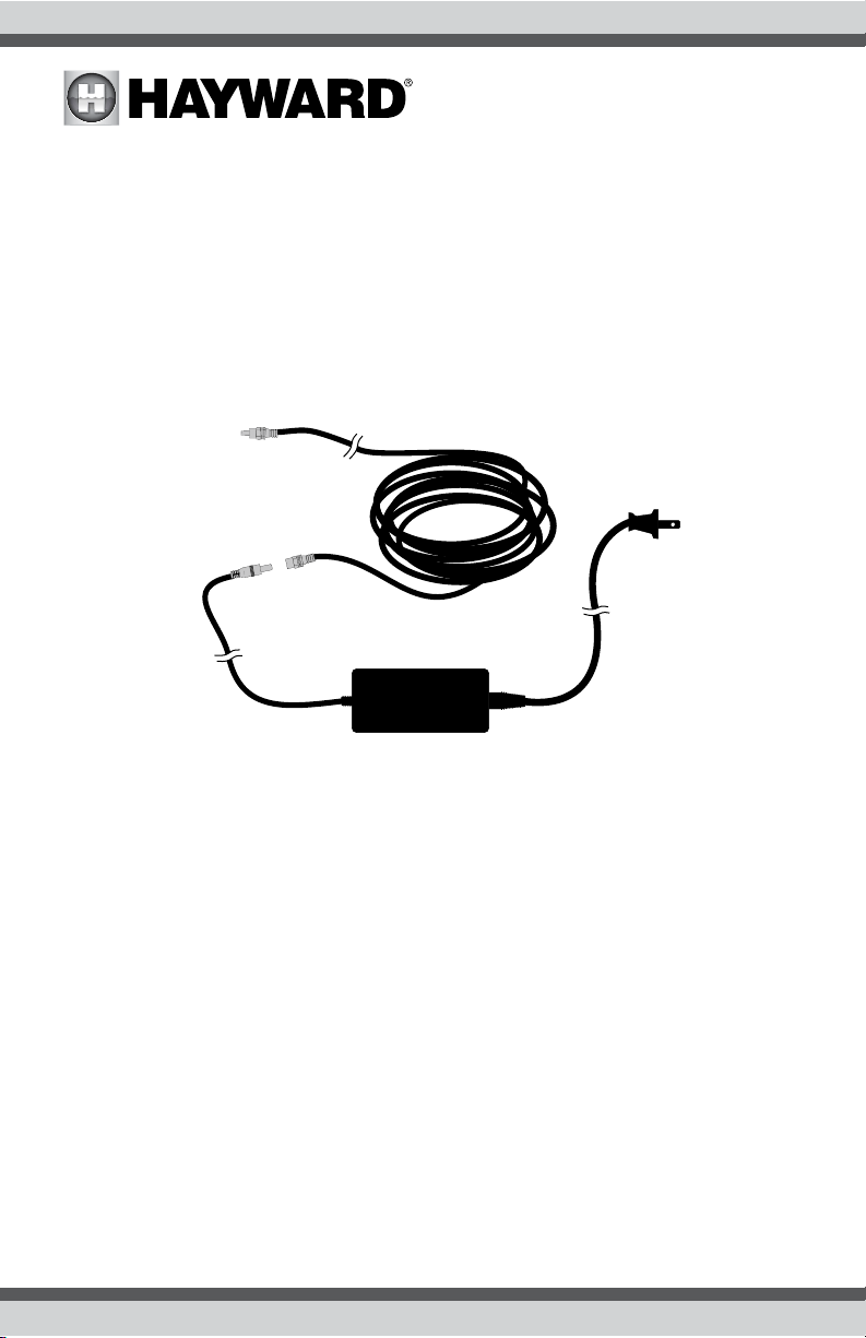
Power Adapter
100’ Power Cable
Power Splitter
Alarm Cable
4 3 2 1
ALARM
These connections
are made inside
of Electrical Box
100’ Ethernet
100’ Power
Cable
Alarm
Module
Camera
to Router

USE ONLY HAYWARD GENUINE REPLACEMENT PARTS
3
Installation
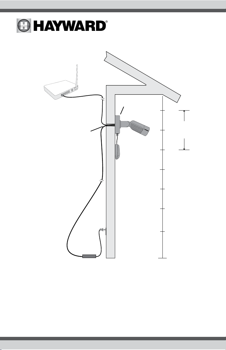
Before installation, give thought to a suitable mounting location and how you will route wiring back
to the Power Adapter and the home’s router or access point. The camera is typically mounted on an
outside wall with power and Ethernet brought to the Electrical Box from indoors. The power supply
will be plugged into an indoor wall receptacle as shown on page 4 and 6.
The ideal mounting height for the PoolScout Camera is 7-10 feet off of the ground tilted downward.
The Alarm Module must mount close enough to the camera so that the Alarm Cable will reach.
Factor in an additional length that will be routed through the back of the Alarm Module.
The final mounting location should allow for a clear view of the entire pool and surrounding area at
all times. Do not allow anything such as sunshades, basketball hoops or other pool side objects to
block the camera’s view, even temporarily.
The ideal mounting location:
• should provide an unobstructed view of the pool and at least 6 feet of the surrounding area
• should allow for convenient two way audio with people in the pool area
• should be 7-10 feet off the ground
• shouldn’t interfere with its surroundings or be vulnerable to damage
• should be accessible from the inside of the exterior wall where the PoolScout will be mounted
• should allow for the 100 foot ethernet cable to be run from the home network’s access point
• should allow for the 100 foot power cable to be run from the power adapter
• should allow for the alarm module to be mounted less than 3 feet away from the camera
If satisfied with the proposed mounting location, mark the spot.
Camera Adjustment
The PoolScout will fasten to the supplied Electrical Box and its mount has a fully articulating hinge.
By loosening the locking screws, you can rotate the mount and camera as shown in the diagram
below. Loosen the locking screws and roughly position the camera in its intended location.
6’ min
6’ min
1. Camera should be rotated to align with the
horizon
2. Camera to tilt downward towards pool
3. Camera should view as much of the pool and
surrounding area as possible
1.
1.
2.
2.
3. 3.
USE ONLY HAYWARD GENUINE REPLACEMENT PARTS
4
Mounting
As shown above, an access hole is needed to run the cables that will power and communicate with
the PoolScout. An existing outdoor opening may be considered if you can route the cables through
from indoors. If not, a hole will need to be drilled. Use a ½” drill bit and make sure that there are no
in-wall pipes or electrical wires in the drill path. Before drilling, fit the Electrical Box over the previ-
ously marked spot. Make sure that it can be centered over the hole and properly fastened to the
surface. Also, plan the orientation of the exit fitting and the mounting location of the Alarm Module
before drilling.
Camera
Alarm
Module
Power
Adapter
Power
Cable
Ethernet
Cable
Electrical
Box
Wall
Receptacle
Ideal
Height
Router
10’
7’
Access
Hole

USE ONLY HAYWARD GENUINE REPLACEMENT PARTS
5
Electrical Box
After drilling the access hole, remove the Electrical Box cover and rear knockout. Center the box
over the hole to test fit. Position the exit fitting (used for Alarm Module wiring) where desired. If
satisfied, spread caulk around the outside back of the Electrical Box, leaving a small space at the
bottom for water to run out. Fasten the Electrical Box using the included hardware. If the hardware
is not suitable for the mounting surface, use appropriate hardware purchased separately.
With the cover off, test fit the Power Splitter cable inside of the Electrical Box and run the 4 con-
ductor end of the Alarm Cable out of the Electrical Box exit fitting. This should give you an estimate
of where the Alarm Module can be mounted (within approximately 3 feet of the camera).
Connections inside of the Electrical Box
The connections shown below will be made inside of the Electrical Box. Refer to the diagram and
the following sections in this manual.
Ethernet Cable
Plug one end of the 100’ ethernet cable into a LAN port on the home network’s router or access
point. Route the other end to the access hole and into the Electrical Box. Plug the ethernet cable
into the camera’s ethernet jack. Because this connection will be housed within the Electrical Box,
the watertight cover on the camera’s ethernet jack can be removed and discarded. You may need
to coil up excess cable indoors before permanently installing at the Electrical Box. When routing is
complete, secure the cable along the run using the supplied cable clips.
4 3 2 1
ALARM
Electrical
Box Cover
Not Used
100’ Power
Cable Power Splitter
Exit
Fitting
Alarm
Cable
100’ Ethernet
Alarm
Cable To
Camera
Electrical
Box
Access
Hole
USE ONLY HAYWARD GENUINE REPLACEMENT PARTS
6
PoolScout Camera
The PoolScout Camera mounts to the Electrical Box cover using four stainless steel fasteners into
pre-drilled holes. Do not install the box cover and camera until wiring is completed.
Power Cable
Plug the 100’ Power Cable into the Power Adapter. Find a convenient indoor wall receptacle and
position the Power Adapter in a permanent location close by (do not plug it into the receptacle until
installation is complete). Run the other end of the 100’ power cable to the access hole and into the
back of the Electrical Box. You may need to coil up excess cable indoors before routing to the Elec-
trical Box. When routing is complete, secure the cable along the run using the supplied cable clips.
Plug into 120V
Indoor Receptacle
Run 100’ Power Cable
to Access Hole

USE ONLY HAYWARD GENUINE REPLACEMENT PARTS
7
Alarm Cable and Alarm Module Wiring
As shown below, the one side of the Power Splitter will plug into the PoolScout Alarm Cable. The
Alarm Cable power connector will come prewired to the RED and BLK conductors. In addition to
the power connector, there are two additional conductors (WHT and YEL) that must be wired to the
camera’s alarm connector. With the cover removed, connect the 4 conductors of the Alarm Cable to
the screw terminal block inside of the Alarm Module as shown below. Route the Alarm Cable from
the back of the Alarm Module according to the diagram.
Carefully coil excess wire into the Electrical Box and fasten the cover using the original hardware.
The camera can now be mounted onto the Electrical Box cover.
PoolScout Alarm Module
With the Alarm Cable connected, you can now mount the Alarm Module. Mount the alarm in the
desired location. If the included hardware is not suitable for the mounting surface, use appropriate
hardware purchased separately. Route the Alarm Cable in manner where it will not get pinched
when the Alarm Module is fastened.
Alarm
Cable
4 3 2 1
ALARM
YEL
&
RED BLK WHT
1 2 3 4
4 3 2 1
ALARM
4 3 2 1
1 White
2 Yellow
3 not used
4 not used
1 Yellow & Red
2 Black
3 not used
4 White
Power
Splitter
Alarm Connector

USE ONLY HAYWARD GENUINE REPLACEMENT PARTS
8
Operation
1. Using the home owner’s phone or other mobile device, install the Hayward PoolScout app
from the App Store®or Google Play®.
2. Follow the app instructions to setup the user account and connect the PoolScout app.
3. When finished with the account verification, the app will guide you through the steps and
prompt you to scan the QR code. Use the mobile device’s camera to take a picture of the QR
code found on the underside of the PoolScout camera (if the PoolScout camera is not avail-
able, the QR code can also be found in the PoolScout box). The PoolScout Camera will then be
associated with your account.
4. To complete the account setup, the app will guide you through the steps for the Pool Setup
and adding People to your PoolScout account.
5. Plug the Power Adapter into the indoor wall receptacle. If connected to the home router, the
camera will automatically initiate a connection to the PoolScout servers . After a short time
your camera’s video footage should be seen through the app. Ensure that the desired outdoor
area is seen and make adjustments to the mount if necessary.

USE ONLY HAYWARD GENUINE REPLACEMENT PARTS
9
Popular Security System manuals by other brands


EDM
EDM Solution 6+6 Wireless-AE installation manual

Highway Safety Group
Highway Safety Group EA401 user manual

Siren
Siren LED GSM operating manual

Detection Systems
Detection Systems 7090i Installation and programming manual

Se-Kure Controls
Se-Kure Controls MicroMini SK-4841 instructions

Siemens
Siemens FDM273 manual