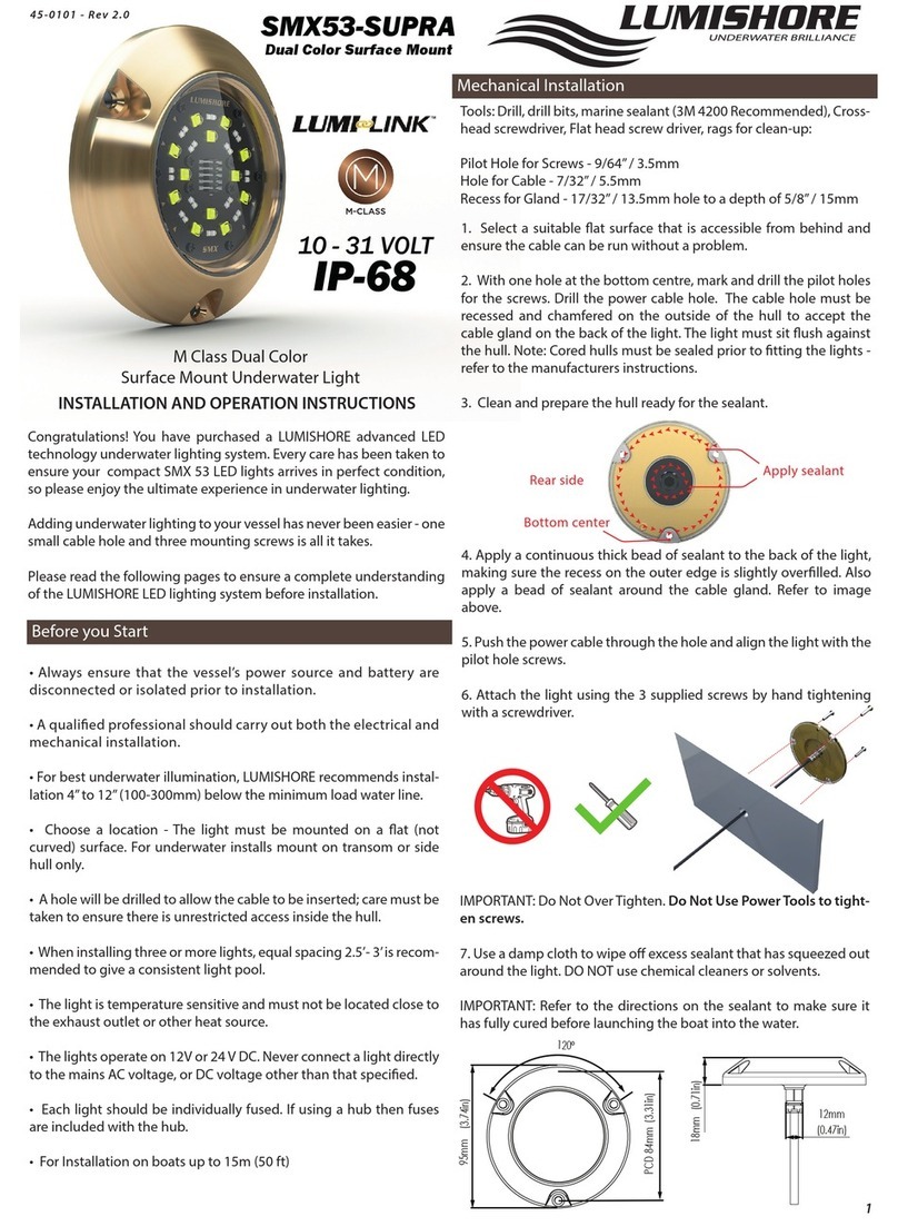
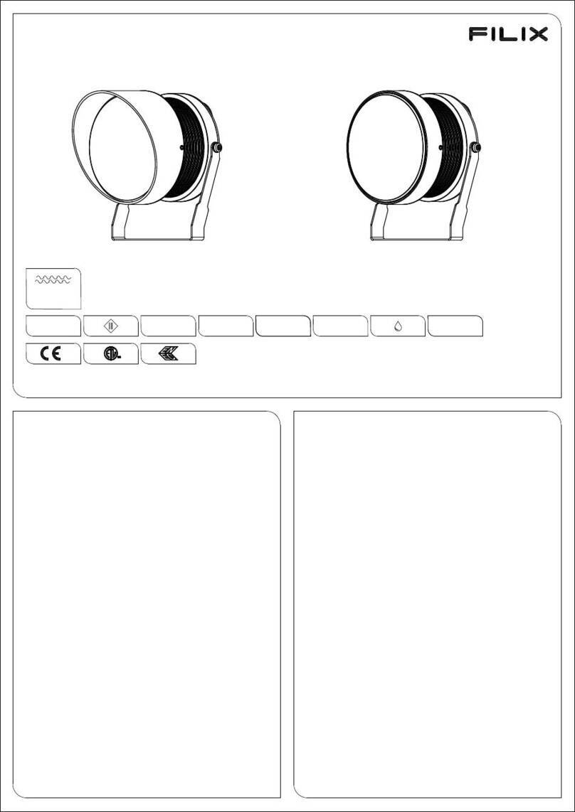
Hayward 7016849 User manual

PRNOTICE - REV I - 11
- P.I.P.A. - Allée des Chênes - 01150 Saint Vulbas - France
www.hayward.fr

2
1 PRX7007 (PREMIUM)
1 PRDX240 (DESIGN)
1 PROX440 (OMEGA)
2 PRX9513
3 PRX20008
4 PRX20005
5A+B PRXVS
6 PRX9472
7 PRX20020
8 PRX9470ABS (BETON)
8 PRX9471ABS (LINER)
8 PRX9474ABS (PANNEAU)
9 PRX20021
10 PRX9120
11 PRX20007
12 PRX20018
Informations indicatives, représentations “photos & schémas” non contractuelles.

3
Le projecteur doit éclairer dans le sens opposé à la maison ou à la terrasse pour ne pas gêner par un éclairage trop
violent.
Le projecteur doit être positionné à 60 cm. au maximum sous la margelle depuis l’axe de l’ampoule. La niche du
projecteur est pourvue de deux sorties 3/4». La sortie arrière est généralement utilisée pour les piscines maçonnées
et la sortie verticale pour les piscines panneau.
300 W - 12 V - AC / Utiliser un transformateur de sécurité avec un secondaire > ou égal à 300 VA sous 12 V
• Poser la protection de chantier sur la face avant de la niche.
• Sceller la niche du projecteur dans la maçonnerie. Finir l’enduit à fleur de la face avant, en respectant l’orientation
haute de la niche. Condamner la sortie non utilisée avec le bouchon.
• Poser le joint sur la face avant de la niche du projecteur.
• Poser le joint sur la bride de la niche du projecteur.
• Fixer la bride d’étanchéité après la pose du liner.
• Découper le liner
• Utiliser le gabarit pour le perçage du panneau
• Poser la niche du projecteur par l’intérieur du bassin. La visser sur le panneau après la pose de la mousse, en
positionnant les stries de fixation de l’optique sur le plan horizontal.
• Réaliser l’étanchéité du liner, de la gaine et du câble et la pose de l’optique du projecteur identique au projecteur
liner.
• Sceller la niche du projecteur dans la maçonnerie, la partie avant en retrait pour la réalisation de l’enduit fini ou
du carrelage.
• Réaliser l’étanchéité de la gaine du câble, et la pose de l’optique projecteur identique au projecteur liner.
• Passer le câble de l’optique du projecteur à l’intérieur du presse étoupe. Attention au positionnement de la
garniture du presse étoupe.
• Aiguiller le câble de l’optique du projecteur dans la gaine jusqu’à la boite de connexion.
• Réaliser l’étanchéité du câble avec le presse étoupe. Attention respecter le positionnement de la garniture de ce
presse étoupe. (l’extrémité avec angle 30° est positionnée en fond de corps de presse étoupe).
• Présenter l’optique devant la niche en y enroulant le supplément de câble.
• Encastrer l’optique du projecteur dans la niche en positionnant les griffes dans les stries.
Le remplacement de pièces doit être effectué avec des pièces d’origines.
Lors d’un changement d’ampoule et/ou du câble, il est préconisé de changer la totalité des pièces assurant
l’étanchéité. Type de lampe utilisé : PAR 56 en cas de nécessité de changement de la lampe, utiliser la pièce d’origine.
Si le cordon d’alimentation ou la gaine est endommagé, il doit être remplacé par le fabricant, un Centre Service Agréé
ou un technicien qualifié afin d’éviter tout accident.
• Raccorder la gaine du projecteur à la sortie 3/4“ située sur le fond de la boîte de connexion.
• Les sorties des côtés permettant le passage des câbles d’alimentation électrique.
Préconisation de raccordement : raccorder dans la boite de connexion (non fournie) IPX5, l’extrémité du câble à
l’alimentation venant du local technique, utiliser les blocs de jonctions fournis avec les boites de connexion pour
raccorder le projecteur à l’alimentation en torsadant les fils et serrant bien les vis des bornes de jonctions.
• Le fabricant ne pourra être tenu pour responsable d’un dommage direct ou indirect provenant d’une utilisation ou
installation incorrecte du produit.
• Informations indicatives, représentations, photos et schémas non contractuels.

4
Point the projector away from the house or terrace, so as not to create an excessively bright illumination.
The projector should not be positioned more than 60 cm under the coping, as measured from the centre of the bulb.
The projector’s niche incorporates two 3/4’’ outlets. The rear outlet is generally used for masonry swimming pools,
while the vertical outlet is primarily intended for swimming pools built from panels.
300 W - 12 V - AC / Use a safety transformer with an output greater than or equal to 300 VA at 12 V.
• Fit the site protection on the front of the niche.
• Seal the projector’s niche into the masonry, making sure that you position it the right way up. Fit the plug in the unused
outlet. Take necessary steps to ensure that you can subsequently apply rendering around the front panel.
• Fit the seal on the front panel of the projector’s niche.
• Fit the seal on the flange of the projector’s niche.
• Secure the sealing flange after installing the liner.
• Cut the liner
• Use the template for cutting the panel. Install the projector’s niche from within the basin. Screw it onto the panel
after fitting the foam in position, positioning the lighting unit securing striae horizontally.
• Proceed with sealing the liner, flexible conduit and cable, and install the lighting unit of the projector identical to
the liner projector.
• Seal the niche of the projector into the masonry; the front part should be recessed, so that finishing rendering or
tiling can be applied subsequently.
• Proceed with sealing the flexible conduit and cable, and install the lighting unit of the projector in the same way
as for the vinyl light.
•
Push the projector’s lighting unit cable through the cable gland. Warning, respect the positioning of the gasket
of the bushing.
•
Thread the cable of the projector’s lighting un
it through the flexible conduit up to the connection box.
• Seal the cable gland around the cable. Warning, respect the positioning of the gasket of the bushing. (the end with
angle 30° is positioned in bottom of body).
• Place the lens in front of its housing rolling up any extra cable.
• Fit the projector’s lighting unit into the niche, positioning the claws within the striae.
Original components must be used in all replacement operations.
When changing a bulb and/or cable, it is recommended that all components be changed to avoid compromising the
seals. Type of light used : PAR 56, in the event of necessity changing of the light, to use original part.
If the external flexible cable or cord of this light is damaged, it shall be exclusively replaced by the manufacturer or his
service agent or a similar qualified person in order to avoid a hazard.
• Connect the light flexible conduit to the 3/4’’ outlet located on the bottom of the connection box.
• The outlets on the sides allow throughway for electrical power cables.
Recommendation of connection : to connect in the junction box (not provided) IP X 5, the end of the cable for electrical
power supply coming from the technical box, use the connector blocks provided with the junction box to connect the
spotlight to the power supply by twisting the wires and ensuring that the terminal screws are well tightened.
• The manufacturer can not be considered as responsible for a direct or indirect damage resulting from an use or
an incorrect installation of the product.
• Indicative information, not contractual photos and schema.

5
Der Projektor muß im Haus oder auf der Terrasse in der Gegenrichtung beleuchten, um nicht durch eine zu starke
Beleuchtung zu stören.
Der Projektor muß maximal 60 cm unter dem Brunnenrand von der Achse der Glühbirne ent-fernt sein. Die Nische
des Projektors ist mit zwei 3/4» Ausgängen versehen. Der hintere Aus-gang wird im Allgemeinen für gemauerte
Schwimmbecken verwendet und der vertikale Aus-gang für Paneel-Schwimmbecken.
300 W - 12 V - AC / Verwenden Sie einen Sicherheitstransformator mit einem Sekundär > oder gleich 300 VA unter 12
V.
• Bringen Sie den Baustellenschutz an der Vorderseite der Nische an.
• Versiegeln Sie die Nische des Projektors im Mauerwerk. Schließen Sie den Putz der Vorderseite bündig ab und
beachten Sie dabei die obere Ausrichtung der Nische. Verschlie-ßen Sie den nicht verwendeten Ausgang mit
einem Stopfen.
• Bringen Sie die Dichtung auf der Vorderseite der Nische des Projektors an.
• Bringen Sie die Dichtung am Flansch der Nische des Projektors an.
• Befestigen Sie den Dichtungsflansch nach der Anbringung der Auskleidung.
• Schneiden Sie die Auskleidung aus.
• Verwenden Sie die Schablone für die Bohrung des Paneels
• Setzen Sie die Nische des Projektors durch das Innere des Beckens ein. Schrauben Sie sie nach der Anbringung des
Schaumstoffs unter Positionierung der Befestigungsriffelung der Optik in horizontaler Ebene auf dem Paneel fest.
• Realisieren Sie die Abdichtung der Auskleidung, der Ummantelung und des Kabels sowie die Anbringung der
Optik des Projektors genauso wie bei der Projektorauskleidung.
• Versiegeln Sie die Nische des Projektors im Mauerwerk, wobei der vordere Teil zur Realisierung des fertigen
Putzes oder der Kachelung zurückgesetzt wird.
• Realisieren Sie die Abdichtung der Ummantelung des Kabels und die Anbringung der Projektoroptik genauso wie
die Projektorauskleidung.
• Führen Sie das Kabel der Optik des Projektors im Innern der Stopfbüchse hindurch. Achten Sie auf die
Positionierung der Ausrüstung der Stopfbüchse.
• Führen Sie das Kabel der Optik des Projektors bis zum Anschlusskasten in die Um-mantelung ein.
• Realisieren Sie die Abdichtung des Kabels mit der Stopfbüchse. Vorsicht, achten Sie auf die Positionierung der
Ausrüstung dieser Stopfbüchse (Das Ende mit einem Winkel von 30° ist am Boden des Körpers der Stopfbüchse
positioniert).
• Präsentieren Sie die Optik vor der Nische und rollen Sie dort das zusätzliche Kabel auf.
• Setzen Sie die Optik des Projektors in die Nische ein und positionieren Sie dabei die Klauen in den Riffelungen.
Der Austausch von Teilen muß mit Originalteilen erfolgen.
Bei einem Austausch der Glühbirne und / oder des Kabels wird empfohlen, alle die Abdich-tung gewährleistenden
Teile auszuwechseln. Typ der verwendeten Lampe: PAR 56. Sollte ein Austausch der Lampe erforderlich sein,
verwenden Sie eine Originallampe.
Wenn das Versorgungskabel oder die Ummantelung beschädigt ist, muß diese(s) vom Her-steller, einem zugelassenen
Kundendienstzentrum oder einem qualifizierten Techniker aus-gewechselt werden, um Unfälle zu vermeiden.
• Schließen Sie die Ummantelung des Projektors am 3/4» Ausgang an, er befindet sich auf dem Boden des
Anschlusskastens.
• Die Ausgänge der Seiten lassen den Durchgang der elektrischen Versorgungskabel zu.
Anschlussvorschriften: In dem Anschlusskasten (nicht im Lieferumfang) IPX5 anschließen, wobei das Ende des
Versorgungskabels vom Technikraum kommt, die gelieferten Anschluss-blöcke mit den Anschlusskästen verwenden,
um den Projektor an die Stromversorgung anzu-schließen und dabei die Drähte verdrehen und die Schrauben der
Verbindungsklemmen gut festziehen.
• Der Hersteller übernimmt keinerlei Haftung für einen direkten oder indirekten Schaden aufgrund einer
unsachgemäßen Nutzung oder Installation des Produkts.
• Angaben zu Informationszwecken, Darstellungen, Fotos und Schemata nicht verbind-lich.
This manual suits for next models
4
Table of contents
Languages:
Other Hayward Underwater Lighting manuals

Hayward
Hayward Proseries SP9120 User manual

Hayward
Hayward UCL Niches User manual

Hayward
Hayward Universal ColorLogic User manual

Hayward
Hayward ColorLogic® 4.0 User manual

Hayward
Hayward UCL Niches User manual

Hayward
Hayward SP0512 Series User manual

Hayward
Hayward Universal ColorLogic User manual

Hayward
Hayward ColorLogic SP0536AF User manual