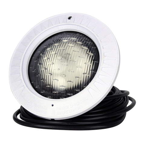
Hayward ColorLogic SP0536AF User manual

ISSP0536 Rev A
1
USE ONLY HAYWARD GENUINE REPLACEMENT PARTS
ColorLogic®Accent
Light Wall Fittings
Owner’s Manual
MODELS:
Gunite Fitting Fiberglass Fitting Vinyl Fitting
SP0536AF (White) SP0537AF (White) SP0538AF (White)
SP0536AFGR (Gray) SP0537AFGR (Gray) SP0538AFGR (Gray)
SP0536AFDGR (Dark Gray) SP0537AFDGR (Dark Gray) SP0538AFDGR (Dark Gray)
SP0536AFBLK (Black) SP0537AFBLK (Black) SP0538AFBLK (Black)
SP0536PR15
IMPORTANT SAFETY INSTRUCTIONS
Basic safety precautions s
h
ou
ld
a
l
ways
b
e fo
ll
owe
d
, inc
l
u
d
ing t
h
e fo
ll
owing: Fai
l
ure to fo
ll
ow instructions
can cause severe injury and/or death.
This is the safety-alert symbol. When you see this symbol on your equipment or in this manual, look for
one of the following signal words and be alert to the potential for personal injury.
WARNING warns about hazards that could cause serious personal injury, death or major property
damage and if ignored presents a potential hazard.
CAUTION warns about hazards that will or can cause minor or moderate personal injury and/or property
damage and if ignored presents a potential hazard. It can also make consumers aware of actions that are
unpredictable and unsafe.
The NOTICE label indicates special instructions that are important but not related to hazards.
Hayward Pool Products
620 Division Street, Elizabeth, NJ 07207
Phone: (908) 351.5400
www.hayward.com
Contents
Warnings……………………….………2
Installation……….……………………4
Installation of SP0536AF……..….5
Installation of SP0536PR15….….6
Installation of SP0537AF….….….6
Installation of SP0538AF…….…..7
Warrantee ………………………………8

USE ONLY HAYWARD GENUINE REPLACEMENT PARTS 2
WARNING - Read and follow all instructions in this owner’s manual and on the equipment. Failure to
follow instructions can cause severe injury and/or death.
WARNING – Suction Entrapment Hazard.
Suction in suction outlets and/or suction outlet covers which are, damaged, broken, cracked, missing, or unsecured can cause
severe injury and/or death due to the following entrapment hazards:
Hair Entrapment- Hair can become entangled in suction outlet cover.
Limb Entrapment- A limb inserted into an opening of a suction outlet sump or suction outlet cover that is damaged, broken,
cracked, missing, or not securely attached can result in a mechanical bind or swelling of the limb.
Body Suction Entrapment- A negative pressure applied to a large portion of the body or limbs can result in an entrapment.
Evisceration/ Disembowelment - A negative pressure applied directly to the intestines through an unprotected suction outlet
sump or suction outlet cover which is, damaged, broken, cracked, missing, or unsecured can result in evisceration/
disembowelment.
Mechanical Entrapment- There is potential for jewelry, swimsuit, hair decorations, finger, toe or knuckle to be caught in an
opening of a suction outlet cover resulting in mechanical entrapment.
WARNING - To Reduce the risk of Entrapment Hazards:
oWhen outlets are small enough to be blocked by a person, a minimum of two functioning suction outlets per pump must
be installed. Suction outlets in the same plane (i.e. floor or wall), must be installed a minimum of three feet (3’) [1 meter]
apart, as measured from near point to near point.
oDual suction fittings shall be placed in such locations and distances to avoid “dual blockage” by a user.
oDual suction fittings shall not be located on seating areas or on the backrest for such seating areas.
oThe maximum system flow rate shall not exceed the flow rating of as listed on Table 1.
oNever use Pool or Spa if any suction outlet component is damaged, broken, cracked, missing, or not securely attached.
oReplace damaged, broken, cracked, missing, or not securely attached suction outlet components immediately.
oIn addition two or more suction outlets per pump installed in accordance with latest ASME, APSP Standards and CPSC
guidelines, follow all National, State, and Local codes applicable.
oInstallation of a vacuum release or vent system, which relieves entrapping suction, is recommended.
WARNING –Failure to remove pressure test plugs and/or plugs used in winterization of the pool/spa from the
suction outlets can result in an increase potential for suction entrapment as described above.
WARNING – Failure to keep suction outlet components clear of debris, such as leaves, dirt, hair, paper and other
material can result in an increase potential for suction entrapment as described above.
WARNING – Suction outlet components have a finite life, the cover/grate should be inspected frequently and
replaced at least every ten years or if found to be damaged, broken, cracked, missing, or not securely attached.
CAUTION – Components such as the filtration system, pumps and heater must be positioned so as to prevent their
being used as means of access to the pool by young children. To reduce risk of injury, do not permit children to use or climb
on this product. Closely supervise children at all times. Components such as the filtration system, pumps, and heaters must be
positioned to prevent children from using them as a means of access to the pool.
WARNING – Hazardous Pressure. Pool and spa water circulation systems operate under hazardous pressure during
start up, normal operation, and after pump shut off. Stand clear of circulation system equipment during pump start up. Failure to
follow safety and operation instructions could result in violent separation of the pump housing and cover, and/or filter housing
and clamp due to pressure in the system, which could cause property damage, severe personal injury, or death. Before servicing
pool and spa water circulation system, all system and pump controls must be in off position and filter manual air relief valve must
be in open position. Before starting system pump, all system valves must be set in a position to allow system water to return
back to the pool. Do not change filter control valve position while system pump is running. Before starting system pump, fully
open filter manual air relief valve. Do not close filter manual air relief valve until a steady stream of water (not air or air and water)
is discharged.
WARNING –Separation Hazard. Failure to follow safety and operation instructions could result in violent separation
of pump and/or filter components. Strainer cover must be properly secured to pump housing with strainer cover lock ring. Before
servicing pool and spa circulation system, filters manual air relief valve must be in open position. Do not operate pool and spa
circulation system if a system component is not assembled properly, damaged, or missing. Do not operate pool and spa
circulation system unless filter manual air relief valve body is in locked position in filter upper body. Never operate or test the
circulation system at more than 50 PSI. Do not purge the system with compressed air. Purging the system with compressed
air can cause components to explode, with risk of severe injury or death to anyone nearby. Use only a low pressure (below 5 PSI),
high volume blower when air purging the pump, filter, or piping.

USE ONLY HAYWARD GENUINE REPLACEMENT PARTS 3
WARNING – Risk of Electric Shock. All electrical wiring MUST be in conformance with applicable local codes,
regulations, and the National Electric Code (NEC). Hazardous voltage can shock, burn, and cause death or serious property
damage. To reduce the risk of electric shock, do NOT use an extension cord to connect unit to electric supply. Provide a properly
located electrical receptacle. Before working on any electrical equipment, turn off power supply to the equipment. To reduce
the risk of electric shock replace damaged wiring immediately. Locate conduit to prevent abuse from lawn mowers, hedge
trimmers and other equipment. Do NOT ground to a gas supply line.
WARNING – Risk of Electric Shock Failure to ground all electrical equipment can cause serious or fatal electrical shock
hazard. Electrical ground all electrical equipment before connecting to electrical power supply.
WARNING – Risk of Electric Shock Failure to bond all electrical equipment to pool structure will increase risk for
electrocution and could result in injury or death. To reduce the risk of electric shock, see installation instructions and consult a
professional electrician on how to bond all electrical equipment. Also, contact a licensed electrician for information on local
electrical codes for bonding requirements.
Notes to electrician: Use a solid copper conductor, size 8 or larger. Run a continuous wire from external bonding lug to
reinforcing rod or mesh. Connect a No. 8 AWG (8.4 mm2) [No. 6 AWG (13.3 mm2) for Canada] solid copper bonding wire to the
pressure wire connector provided on the electrical equipment and to all metal parts of swimming pool, spa, or hot tub, and metal
piping (except gas piping), and conduit within 5 ft. (1.5 m) of inside walls of swimming pool, spa, or hot tub.
IMPORTANT - Reference NEC codes for all wiring standards including, but not limited to, grounding, bonding and other general
wiring procedures.
WARNING – Risk of Electric Shock . The electrical equipment must be connected only to a supply circuit that is
protected by a ground-fault circuit-interrupter (GFCI). Such a GFCI should be provided by the installer and should be tested on a
routine basis. To test the GFCI, push the test button. The GFCI should interrupt power. Push reset button. Power should be
restored. If the GFCI fails to operate in this manner, the GFCI is defective. If the GFCI interrupts power to the electrical equipment
without the test button being pushed, a ground current is flowing, indicating the possibility of an electrical shock. Do not use this
electrical equipment. Disconnect the electrical equipment and have the problem corrected by a qualified service representative
before using.
CAUTION – HAYWARD®pumps are intended for use with permanently-installed pools and may be used with hot tubs and
spas if so marked. Do not use with storable pools. A permanently-installed pool is constructed in or on the ground or in a
building such that it cannot be readily disassembled for storage. A storable pool is constructed so that it is capable of being
readily disassembled for storage and reassembled to its original integrity.
WARNING – Risk of Hyperthermia. To avoid hyperthermia the following “Safety Rules for Hot Tubs” are recommended by
the U.S. Consumer Product Safety Commission.
1. Spa or hot tub water temperatures should never exceed 104°F [40°C]. A temperature of 100°F [38°C] is
considered safe for a healthy adult. Special caution is suggested for young children. Prolonged immersion in
hot water can induce hyperthermia.
2. Drinking of alcoholic beverages before or during spa or hot tub use can cause drowsiness, which
could lead to unconsciousness and subsequently result in drowning.
3. Pregnant women beware! Soaking in water above 100°F [38°C] can cause fetal damage during the
first three months of pregnancy (resulting in the birth of a brain-damaged or deformed child). Pregnant women
should adhere to the 100°F [38°C] maximum rule.
4. Before entering the spa or hot tub, users should check the water temperature with an accurate ther-
mometer; spa or hot tub thermostats may err in regulating water temperatures by as much as 4°F (2.2°C).
5. Persons taking medications, which induce drowsiness, such as tranquilizers, antihistamines or anti-
coagulants, should not use spas or hot tubs.
6. If the pool/spa is used for therapy, it should be done with the advice of a physician. Always stir pool/ spa
water before entering the pool/spa to mix in any hot surface layer of water that might exceed healthful
temperature limits and cause injury. Do not tamper with controls, because scalding can result if safety controls
are not in proper working order.
7. Persons with a medical history of heart disease, circulatory problems, diabetes or blood pressure
problems should obtain a physicians advice before using spas or hot tubs.
8. Hyperthermia occurs when the internal temperature of the body reaches a level several degrees above
normal body temperature of 98.6°F [37°C]. The symptoms of Hyperthermia include: drowsiness, lethargy,
dizziness, fainting, and an increase in the internal temperature of the body.
The effects of Hyperthermia include:
1. Unawareness of impending danger.
2. Failure to perceive heat.
3. Failure to recognize the need to leave the spa.
4. Physical inability to exit the spa.
5. Fetal damage in pregnant women.
6. Unconsciousness resulting in danger of drowning.
SAVE THESE INSTRUCTIONS

USE ONLY HAYWARD GENUINE REPLACEMENT PARTS 4
INSTALLATION:
INSTALLATION DEPTH REQUIREMENT: Except when the wall fitting is installed in an area of the swimming pool
that is not used for swimming and the lens is adequately guarded to keep any person from contacting it, the
fixture must be installed in a wall or on a floor of a pool, spa, or water feature with the top of the lens opening not
less than 4 in. and no more than 72 in. below the normal water level of the pool.
CORD LENGTH AND MINIMUM REQUIRED VOLTAGE:
When installing the ColorLogic Accent low voltage lights, the length of the cord has an effect on performance. To
prevent performance problems, verify the transformer is providing the minimum required voltage according to the
table below. To check this voltage, measure the voltage at the transformer while the light is “on” and operating in
“white” mode. In some cases, a voltage greater than 12 volts is required due to a long cord run. Some
transformers provide higher voltage taps for this purpose; check your transformer manufacturer’s installation
instructions for details. When using Hayward or other transformers that offer a 14v option, we suggest that you
always use the 14 volt tap.
PRODUCT
Total cord
length from
Transformer to
Light
Minimum
Required
Voltage at
transforme
r
12v ColorLogic
Accent Light
30 ft 12-14 volts
50 ft 13-14 volts
100 ft 14 volts
INSTALLATION OVERVIEW
Refer to the diagram below for an overview of the ColorLogic Accent light, to comply with NFPA-70 (NEC) and to
provide the easiest path for the light cord.

USE ONLY HAYWARD GENUINE REPLACEMENT PARTS 5
Installation Location
The wall fitting must be installed in a wall or on a floor of the pool or spa with the top of the lens not less than 4
inches (10 cm) below the normal water level of the pool except when the wall fitting is installed in an area of the
swimming pool that is not used for swimming. Select a location for the light fixture(s) that will give optimum light
dispersion for the pool or spa design. Be sure to consider the direction of emitted light and take care not to point
lights directly at the house or outdoor living spaces.
Install Junction Box or Junction Box Transformer
When using a wall mount low voltage transformer, a junction box should be installed to make the connection to
the pool/spa light. If using more than one light, an adequate amount of single or double outlet junction boxes
will be required. Alternatively, Hayward low voltage junction box transformer kits (LTBUY11H65) can be used
when in-line transformers are desired.
Junction boxes must be installed not less than 48 inches (1.22 m) from the edge of the pool or spa. Run conduit
from the mounting location up to the junction box such that the junction box is not less than 8 inches (20 cm)
above the maximum pool or spa water level, or not less than 4 inches (10 cm) above the ground, whichever is
greater. Additional conduit should be run from the junction box to the power supply, switch panel, pool/spa
controller, etc.
Install the Hayward ColorLogic Accent Light - Gunite Pools
The ColorLogic Accent Light installs in a 1.5” PVC pipe that will be installed through the pool wall.
For Gunite pools, the SP0536AFXXX wall fitting should be used.
1) Determine the desired installation location.
2) Solvent cement a 14” long piece of 1 1/2” Sch 40 PVC
pipe into the SP0536A Fitting Body.
3) Position the assembly through the proposed pool
wall. The backface of the SP0536A Fitting Body
should end up flush with the Gunite wall surface as
shown.
4) Cover the openings with duct tape.
5) Apply Gunite to pool walls.
6) The Plaster surface should be flush to the top of the
flange.

USE ONLY HAYWARD GENUINE REPLACEMENT PARTS 6
Alternate Installation of the Hayward ColorLogic Accent Light - Gunite Pools
The ColorLogic Accent Light installs in a 1.5” PVC pipe at least 14” long installed through the pool wall.
For Gunite pools, the SP0536PR15 wall fitting can be used.
1) Determine the desired installation location.
2) Slide the Collar onto the 1 ½” PVC pipe. Position it
flush to the pool wall.
3) Solvent cement into place.
4) Cover the openings with duct tape.
5) Apply Gunite to pool walls.
6) After curing, cut the PVC pipe 1/8” beyond the Gunite
Collar as shown.
7) The Plaster surface should be flush to the end of the
pipe.
Install the Hayward ColorLogic Accent Light in Fiberglass and Vinyl Pools
Like Gunite pools, the ColorLogic Accent Light installs in a 1.5” PVC pipe that will be installed through the pool
wall. Use the SP0537AFXXX 1 1/2” wall fittings on Fiberglass pools, and Vinyl Pools.
1) Determine the desired installation location.
2) Solvent cement a 14” long piece of 1 1/2” Sch 40 PVC pipe into the SP0536A Fitting Body.
3) SP0537 Fitting is for a pool with a vinyl liner and for fiberglass pools are provided with a Flanged
Nut, and two (2) gaskets and a washer. The gaskets should be placed such that they sandwich the
liner or fiberglass, that is, one gasket on each side. The Fitting body passes through both gaskets,
the liner, the washer and finally the nut. The flange is on the inside of the pool. See diagram
below.
4) The hole size should be between 2.360” and 2.400” in diameter. Usually a 2 3/8” hole will work.
Be careful not to tear the liner.
5) A Small amount of silicon sealant applied to the gaskets on the liner side will aid in sealing.
Item Description Number Required
1 FLANGED NUT 1.00
2 GASKET 2.00
3 FIBER WASHER 1.00
4 FITTING BODY 1.00

USE ONLY HAYWARD GENUINE REPLACEMENT PARTS 7
Install the Hayward ColorLogic Accent Light in vinyl lined pool.
1. The SP0538AFXXX fitting is intended to be used in a pool that has a vinyl liner. Pool wall thickness must be
equal to or below 1/4” or between 5/8” and 1”.
2. Make one circular cut-out in pool wall minimum 3” in diameter and maximum 3-1/16” in diameter.
3. Insert fitting body through the inside of the pool wall until the underside of the flange is flush against the wall.
If pool wall is 1/4” or less in thickness, screw combo locknut-spacer onto fitting body with polygon side to rear
(as shown below). To hold fitting in place against pool wall, tighten combo locknut-spacer firmly by hand—
then turn 1/2 of a revolution with suitable channel locks (DO NOT OVERTIGHTEN),. If pool wall is between 5/8”
and 1” thick, reverse orientation of combo locknut spacer and screw on as described above.
4. Install the pool vinyl liner.
5. Place face plate on the inside wall of pool, making sure the holes in the face plate are lined up with the holes
in the body of the fitting. Pierce the vinyl pool liner through face plate one hole at a time prior to inserting
screws.
6. Fasten face plate to fitting body with the four (4) 1” screws provided. Screw through Face Plate, Vinyl Liner,
and into Fitting Body.
7. Cut-out vinyl liner along inside edge of face plate.
8. A minimum 14” long piece of 1 ½” schedule 40 PVC pipe is required to be solvent cemented into the SP0538A
body.
Item Part Number Description Number Required
1 SPX1039Z1A 1” Flat Head Screw Pack 1 (Pack of 4)
2 SPX1408B Face Plate 1
3 SPX1408C Gasket 1
4 Fitting Body 1
5 SPX1407D Combo Locknut-Spacer 1
Note: Alternate color face plates SPX1408BGR, SPX1408BDGR, and SPX1408BBLK are available

USE ONLY HAYWARD GENUINE REPLACEMENT PARTS 8
All SKU’s for these wall fittings come complete with a HAL-Retainer SP0536C which is color matched to
the fitting. This HAL Retainer is used to mount the Accent Light.
Accent light installation requires a special tool SP0536CTOOL which comes with each Accent Light.
Hayward and Color Logic are registered
trademarks of Hayward Industries, Inc.
© 2014 Haywa
r
d Industries, Inc.
HAYWARD®Pool Products Limited Warranty
To original purchasers of this equipment, Hayward Pool Products, Inc. warrants its wall fittings to be free from defects in materials and workmanship
for a period of ONE (1) year from the date of purchase, when used in single family residential applications.
The limited warranty excludes damage from freezing, negligence, improper installation, improper use or care or any Acts of God. Parts that fail or
become defective during the warranty period shall be repaired or replaced, at our option, within 90 days of the receipt of defective product, barring
unforeseen delays, without charge.
Proof of purchase is required for warranty service. In the event proof of purchase is not available, the manufacturing date of the product will be the
sole determination of the purchase date.
To obtain warranty service, please contact the place of purchase or the nearest Hayward Authorized Service Center. For assistance on your nearest
Hayward Authorized Service Center please visit us at www.hayward.com.
Hayward shall not be responsible for cartage, removal, repair or installation labor or any other such costs incurred in obtaining warranty replacements
or repair.
The Hayward Pool products warranty does not apply to components manufactured by others. For such products, the warranty established by the
respective manufacturer will apply.
The express limited warranty above constitutes the entire warranty of Hayward Pool Products with respect to its’ pool products and is in lieu of all other
warranties expressed or implied, including warranties of merchantability or fitness for a particular purpose. In no event shall Hayward Pool products be
responsible for any consequential, special or incidental damages of any nature.
Some states do not allow a limitation on how long an implied warranty lasts, or the exclusion of incidental or consequential damages, so the above
limitation may not apply to you. This warranty gives you specific legal rights, and you may also have other rights, which vary from state to state.
Hayward Pool Products
620 Division Street
*Supersedes all previous publications. Elizabeth, NJ 07207
This manual suits for next models
12
Table of contents
Other Hayward Underwater Lighting manuals

Hayward
Hayward Universal ColorLogic User manual

Hayward
Hayward 7016849 User manual

Hayward
Hayward UCL Niches User manual

Hayward
Hayward SP0512 Series User manual

Hayward
Hayward ColorLogic® 4.0 User manual

Hayward
Hayward Proseries SP9120 User manual

Hayward
Hayward Universal ColorLogic User manual

Hayward
Hayward UCL Niches User manual
Popular Underwater Lighting manuals by other brands

Astral Pool
Astral Pool SKIMMER FLOTANDO Installation and maintenance manual

Sea & Sea
Sea & Sea YS-D3 instruction manual

Lumascape
Lumascape LS333ANS-2COB installation instructions

LIGMAN
LIGMAN BORNHOLM 1 installation manual

Certikin
Certikin PU9CLS Installation

Kripsol
Kripsol PH300.C Manual for the installation, use and maintenance