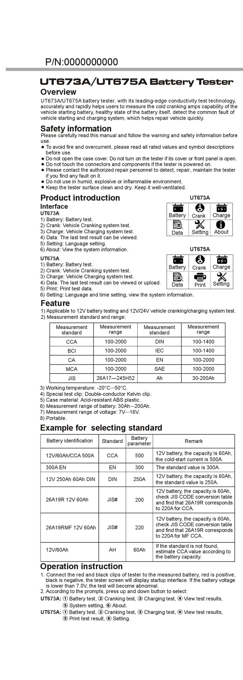
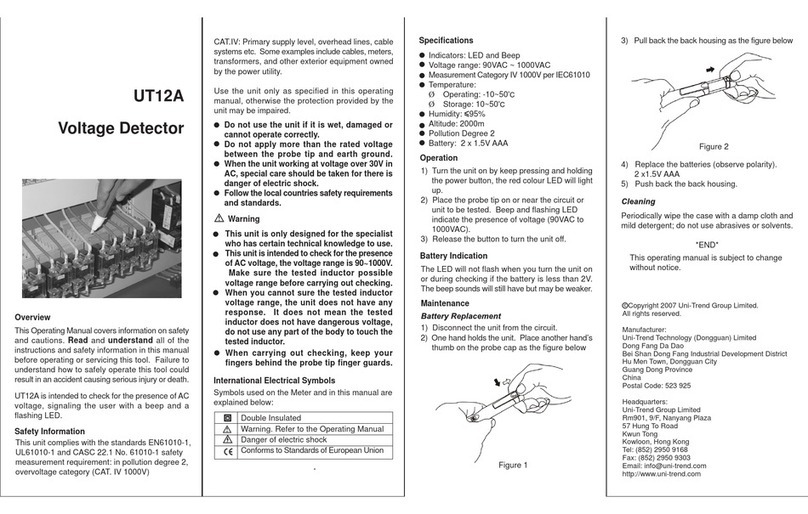
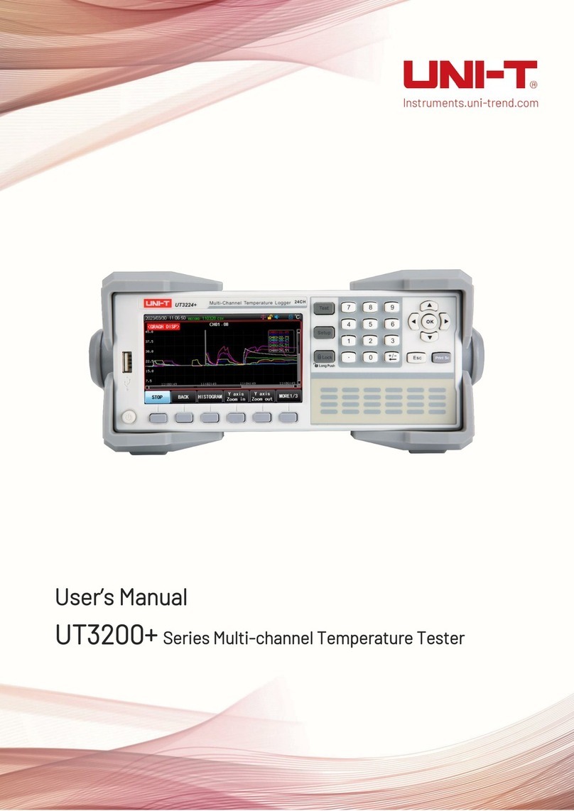
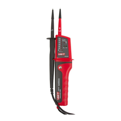
Unit UTD1025CL User manual

Preface
Dear users:
Hello! Thanks for you choosing the brand new UNI-T device. In order to use the instrument correctly,
please read the manual thoroughly and especially the Safety Notes part before using the device.
If you have read through the manul, you are recommended to keep the menu properly with the instrument
together or at the place you can read anytime in order to read it in the process of future use.

Contents
Item
ChapterI Safety Information
Chapte II Brief Instroduction of the UTD1025CL Portable Digital Storage
Oscilloscope
UTD1025CL Oscilloscope Components
Features of UTD1025CL Oscilloscope
Chapter III Oscilloscope Connection
How to Conduct General Check
Check If Any Damage Resulted By Transportation
Check Accessory
Check the Complete Apparatus
Oscilloscope Connection
Compensation Signal Output Connection of the Apparatus
Oscilloscope panels and keys
Chapter IV Primary Application of Oscilloscope
Connect Appatatus to the Electricity Power
nterface Instruction
...............................
..............
............................................
...............................
.....................................
.......
.................................
.......................
.....................
.........................................
I.
Page
General safety Overview
.........................................
......................................................
.................................
4
.......................... 5
...........................
Preface
1
5
6
6
6
6
7
7
8
8
12
12
12
UTD1000L User Manual

Item
Oscilloscope Switch-In Probe Compensation Signal
Probe Compensation
Trigger Level
Munual Set Vertical System Horizontal System and Trigger Level,
Horizontal System
Automatic Setting of Waveform Display
Stop/Restore Data Collection
Trigger Frequency Count Setting
Screen Brightness Adjustment
Store Bitmap
Online Help
Set Single Trigger
Check Oscilloscope Status
.
.....................
..............................................
.
.................................
..............................
...............................
.................................................
..........................................
...................................
Page
.............
............................................
.........
...............................................
.....................................................
14
14
15
15
16
17
18
18
19
21
21
22
23
23
23
24
Operation Methods for Function Menu........................
Reset Oscilloscope
....................................
UTD1000L User Manual
Menu Hiding..............................................

Item
....................
............................................
............................................
.....................................
Automatic Parameter Measurement
Customization Parameter Measurement
Smooth Waveform by Average Treatment
Interface Indication Instruction
Multimeter Measurement
Measure Resistance Value
Measure Diode
Continuity Test
Measure Capacitance
Display Spike Pulse by the Peak Value Test Function
Use Persistence to Show Waveform
Select AC Coupling
Reverse Polarity of the Displayed Waveform
Automatic Setting for Small Signal with DC Bias
Connect Apparatus
Page
25
.............................
.........................
.................
..............................................
...................................
........................................
.......................................
........................
............
.............................
..............................................
.....................
Chapter V Use Multimeter...........................................
UTD1000L User Manual
Check Oscilloscope System Information
25
26
27
28
28
29
29
30
32
32
32
33
33
34
34
35

Item
Measure DC Current
Measure current
Hold Measurement Value
Relative Measurement
Select Automatic/Manual Range Adjustment
Chapter VI Details about Using Oscilloscope
Horizontal Sysmem Setting
AC
Vertical System Setting
Trigger System Setting
Collection Mode Setting
Display Set
Parameter Measurement Setting
Storage and Record
Record Function
Storage Function
..................
.......................................
..............................
Page
.............................................
..............................................
........................................
...........................................
............................
..........................................
......................................
...........................................
..................................................
.........................................
............................................. 65
.............................................68
.
36
36
37
39
41
41
42
43
43
46
49
57
58
60
65
Measure AC Voltage....................................
Measure DC Voltage...................................
UTD1000L User Manual

Item
Callback Function
Cursor Measurement
nterface Set
Auxiliary Function Set
Mathematic Operation Function
Automatic Set
Product Program Upgradation
Program Upgradation Conditions
Program Upgradation
Appendix A : Performance Index
Appendix B: Maintenance and Cleaning
............................................69
.........................................71
................................................
.......................................
...............................
...............................................
........................................
I
Preparations before Upgradation
............................
Page
...................................
...............................
..............................
......................
.
Chapter VII Troubleshooting.....................................
Chater VIII Service and Support......................................
Chapter IX Appendix............................................
UTD1000L User Manual
73
74
75
78
79
81
81
81
81
81
84
84
92

ChapterI Safety Information
Safety Terms and Symbol
Symbols on the product
Terms in the manual
Warning:
Notes:
Terms on the product
Danger:
Warning:
Notes:
The following terms might be in the manual:
warning statement indicates the
conditions and activities that might endander life
noting statement indicates the conditions and
activities that might cause damage to the product and
other property.
The following terms might be on the product:
it means reading the symbol might be
harmful to you immediately.
it means reading the symbol
it means damage might be caused to the
product or other property.
The following symbols might be on the product:
.
1
Please pay attention
to the Manual
High voltage Measurement of
the ground port
UTD1000L User Manual

General Safety Overview
The apparatus is strictly designed and produced
under the GB4793 Safety Requirements for
Electronic Measuring Apparatus and IEC61010-
1Safety Standard. The apparatus meets the over
voltage standard CAT V and safety
standards for pollution level II
Please read the following safety prevention
measures to prevent personal injury and any
damage to the product or other products connected
with the product. To avoid any possible danger, the
product shall be applicable in the stitulated
scope and be repaired by the specially trained
personnel.
To use the voltage probe, test lead wire and
adapter with certain insulation attached with the
oscilloscope or use the accessories designated by
UNI-T applicable to oscilloscope apparatus
series product.
Before using, check if any mechanic damage to
the multimeter test pen, oscilloscope probe and
accessories and please replace it if any damage
were found.
To remove all unused test pen, probe an
accessories.
To insert adapter into the AC socket and connect
it with the oscilloscope
In measurement in the CAT ambient don t
connect the voltage higher than 300V with the
oscilloscope input port and don t connect the
voltage higher than 600V with the multimeter input
port in the CAT ambient
Ⅲ 600
.
.
:
.
Ⅲ,'
'
Ⅲ.
Warning: to prevent electric shocking or fire,
please use the dedicated adapter approved to
apply in the country
Warning: if the oscilloscope input port were
connected with the voltage higher than 42 V 30
Vrms),to avoid electric shocking please
(
●
●
●
●
●
UTD1000L User Manual
2

UTD1000L User Manual
●
●
●
●
●
●
In measurement in the CAT ambient don t
connect the voltage with voltage difference higher
than 300V with the oscilloscope input port and
don t connect the voltage with voltage difference
higher than 600V with the multimeter input port in
the CAT ambient
Ⅲ,'
'
Ⅲ.
Don t use the input voltage higher than
apparatus rating value
Use accessories attached with the product and
cease using it if any damage to it.
Don t plug any metals into the socket.
Use the oscilloscope with the designated
method
The voltage rating value mentioned in the
Warning information is the limit value of adapter
Working Voltage they represent the Vrms 50-
60Hz ofACsinewaveinuse
to
avoid fire or electric shocking please pay
attention to all rating values and marks
Don t operate if there is any suspected trouble:
please let the qualified maitainence personnel to
check the product suspected being damaded
'
'
.
;(
).
.
':
,
.
'
.
'
'
Maintenance shall be conducted only by
qualified techinicians
Pay attention to all terminals rating value
Please don t operate in the moist anbient.
Please don t operate in the explosive anbient.
Keep product suface clean and dry.
3

UTD1000L User Manual
4
Chapte II Brief Instroduction
of the UTD1025CL Portable
Digital Storage Oscilloscope
Brief Instroduction of the UTD1025CL
Portable Digital Storage Oscilloscope
The UTD1025CL series of digital storage
oscilloscope referred hereinafter as
oscilloscope are a perfect combination of
usability, uniquie technical index and multipurpose,
helping users completing test more quickly.
The manual concludes the following types:
The UTD1025CL series of digital storage
oscilloscope provides a simple and functionally
clear front panel, enabling to conduct all basic
operations meeting the use habit of traditional
instrument and enabling the user to operate it
proficiently without taking much time to learn and
be familiar with operation of the digital storage
oscilloscope. In order to speed up the adjustment
for measuring, the user can press directly the
button AUTO , and then the instrument shall show
the proper waveform and the gear setting
Apart from the usability, UTD1025CL series of
digital storage oscilloscope possess high
efficiency index and powerful functions required
for quick measuring. To simplify the menu
operation, the combination operation of key
SHIFT on the apparatus and other keys can
enable direct operation of more functions
Besides, the powerful trigger and analysis ability
shall make it easier to capture and analyze the
waveform.The clear liquid crystal display and
(
)
,
.
.
Type Bandwidth Sampling
velocity
Channel
count
Single channel
UTD1025CL 25MHz 200MS/s
mathematical operations help users to observe
and analyze the signal problems more quickly
and clearly
Unpacke the oscilloscope case, you ll see the
following components:
Full-automatic setting function AUTO SCALE)
vertical and time base gear could be
automatically adjusted according to the signal
changes with manual intervention
Unique powerful automatic setting function can
make quick and correct automatic setting about
any signal containing DC components.
Wider voltage measurement scope
20V/div,reach 200V/div in combination with 10
probe
.
'
(
.
UTD1025CL Oscilloscope Components
Features of UTD1025CL Oscilloscope
Oscilloscope
USB isolated communication provides safer
USB communication
Transition from color display to B W display is
applicable in the strong outdoor light.
Smart upgradation function user can upgrade
software by local or network.
Unique waveform recording, storage and
playback function
/
●
●
●
●
●
●
●
5
UTD1000L User Manual
No.
1
2
3
4
6
5
7
8
9
10
Instruction
UNI-T oscilloscope
An adapter
An oscilloscope probe
2 multimeter test pen(a red and a black)
An oscilloscope probe adjusting tool
An UT-M07 module
A USB data line
An user manual
An user disk (inclusive of oscilloscope
and comuter communication software)
A portable soft bag
Standard
configuration
●
●
●
●
●
●
●
●
●
●

UTD1000L User Manual
●
●
●
●
●
●
●
●
●
●
Color liquid crystal display with high resolution
and high contrast
No less than 8 hours of continuous work
Automatically measure 19 types of waveform
parameters
Screen printing function
Help information display both in Chinese and
English
Multimeter
33/4 bit
Voltage, current, resistance, diode, capacitance
and conductive measurement
Current measurement up to 10A
Extremely low current measurement internal
resistance precise measurement results
Mutual isolation between multimeter and
osilloscope
Please check the new oscilloscope under the
following steps if you have one:
If any serious damage of the package carton or
plastic foam protective mat were found, please
contact with the Uni-T distributor or local Uni-T
representative office immediately.
As regards to the provided accessory details, the
above-mentioned UTD1025CL Oscilloscopes
Accessory in the manual has clearly stated it You
can check it if there is any damage to the
accessory in reference to the manual
If any lack or damage of accessories were found,
please contact UNI-T distributor selling the product
,
.
.
Chapter III Oscilloscope
Connection
How to Conduct General Check
Check If Any Damage Resulted By
Transportation
Check Accessory
6

UTD1000L User Manual
7
or the local office of UNI-T.
If any damage of accessory surface, or failure to
work or to pass the function test were found, please
contact with the UNI-T distributor or the local
representative office of UNI-T.
If any damage were found, please keep the
package and contact with the transportation
department and the uni-t distributor that sells the
product, UNI-T shall arrange for the maintenance or
replacement.
The oscilloscope connection is referred to the
picture 3-1
1. Oscilloscope channel input port
2. USB connection port.
3. Adapter interface used for AC power supply and
battery charging.
4. Probe compensation signal output port
5. Multimeter input socket 3 circular banana
sockets are input ports for voltabe resistance
current and COM port
Check the Complete Apparatus Oscilloscope Connection
Instructions
Oscilloscope Connection
:
,
/,
.
Picture 3-1 Oscilloscope Interface

UTD1000L User Manual
Compensation Signal Output Connection of the
Apparatus
As shown in the following picture a
compensation signal (1kHz 3V) output port on the
Left side of the apparatus could be used to adjust
the probe
Panels and keys of oscilloscope are shown in
the picture 3-3
,
/
.
:
Oscilloscope panels and keys
8
Picture Signal Output
Connection of the Apparatus
Compensation3-2 Picture 3-3 UTD1025CL Panel

Power key to power on off oscilloscope
F1 F4:Key for menu option setting
: DSO/DMM key to switch between the
working mode of oscilloscope(DSO) and
multimeter (DMM)
ACQUIRE/*(brightness) V (voltage
measurement) key:under the oscilloscope mode
press the key to enter ACQUIRE (aquire sample)
menu Press the key SHIFT firstly and press it
again to adjust brightness and change the
screen brightness by shifting the left/right keys.
Under the multimeter (DMM) mode, press the key
to enter into the voltage measurement menu.
: DISPLAY/CONFIGURE/[I] current
measurement key: under the oscilloscope mode,
press the key to enter DISPLAY (display mode)
menu Press the key SHIFT firstly and press it
again to enter the CONFIGURE (interface
configuration) menu Under the multimeter
(DMM)mode, press the key to enter into the current
measurement menu
MEASURE/CURSOR/[R] (resistance
measurement) key: under the oscilloscope mode,
press the key to enter COURSOR (sursor
measurement) menu Press the key SHIFT firstly
and press it again to enter the MEASURE
(automatic measurement) menu Under the
multimeter (DMM) mode, press the key to enter into
the resistance measurement menu and to measure
resistance /diode/ continuity/ capacitance.
:MATH/STATUS key under oscilloscope
mode, press the key to enter into MATH
(mathematic operation) menu Press key SHIFT
and press it again you can open the STATUS
(status bar) display
()
()
:/.
~
:
.
:/[]
,
;
(
)
;
.
.
:
;
.
:
;
,
.
:RECORD/STORAGE key under the
oscilloscope mode, press the key to enter into
RECORD waveform record menu Press key
SHIFT and
:
;
press it again you can open the
STORAGE storage menu
,
.
UTD1000L User Manual
9

UTD1000L User Manual
10
:SINGLE/REF key under the oscilloscope
mode, press the key to set SINGLE(single trigger)
function Press key SHIFT and press it again
you can back to the REF(waveform reference)
menu
AUTO key under the oscilloscope mode,
press the key to complete waveform automatic
setting Press key SHIFT and press it again you
can open full automatic setting function under
which the oscilloscope shall adjust apparatus
gear automatically with the changes of input signal
and display the waveform in the fittest form
without manual intervention
RUN/STOP key under the oscilloscope
mode press the key to start or stop data collecting
under the multimeter (DMM) mode, press the key
to hold screen measurement reading.
:
(
(
HORIZONTAL / HELP key under the
oscilloscope mode press the key to enter the
HORIZONTAL (horizontal setting) menu Press
key SHIFT and press it again you can open the
HELP (help) information
SHIFT key to select functions in
combination with other function keys
Time base used to change scanning
50s/div 10ns/div with 1-2-5 system Press
S the scanning velocity shall slower down a
gear relatively or speeded up
Vertical scale used to change vertical
5mV/div 20V/div with 1-2-5 system Press
V a vertical scale shall be relatively
increased or reduced.
:
;,
.
::
;,
-,
,
.
::
,;
:
,
;
,
.
::
.
::
~.
“”,
.
::
~.
“”,
UTILITY / TRIGGER key under the
oscilloscope mode press the key to enter the
TRIGGER trigger setting)menu Press key
SHIFT and press it again you can enter into the
UTILITY auxiliary function) menu.
:
:
,
;
,
RUN/STOP
SHIFT
velocity. Scanning velocity of the apparatus is
scale gear Scale scope of the apparatus is.

UTD1000L User Manual
11
Press V a vertical scale shall be relatively
increased or reduced.
: Selection key the selection for
switching channel vertical shift and trigger
level shift under normal conditions If vertical
shift have been selected, the vertical reference
triangle cursor on the screen shall be solid and
you can move vertical position on the screen
of the waveform by adjusting the up down
keys If press the key SELECT again the
vertical triangle cursor of trigger level position
shall be solid and you can change the trigger
position by adjusting the up/down keys.
In the MEASURE menu the key used to
confirm the selected Customization parameter
switch cursor 1 and cursor 2 under the cursor
measurement
:“”,
:
.
/
.,
,
;
.
Direction key and OK key OK key used
to hide display the present menu bar
:
/
under normal circumstances under the
multimeter (DMM) mode, the keys are used to
confirm the correct connection of 10A
in A gear current measurement
Open trigger main menu and select
trigger coupling mode and automatic normal trigger
mode by the key F3/F4
;
.
/
.
CURRENT
DIVIDER
SHIFT OK : Store present display interface into
the storage and outputted from the host computer
SHIFT AUTO : open the full-automatic setting
function, under which, the oscilloscope shall adjust
vertical scale and scanning time base automatically
with the changes of input signal and display
the waveform in the fittest form without manual
intervention
SHIFT F1
Introduction about the shortcut operation:
;
.
+
+
+:
+
+
+

Chapter IV Primary Application
of Oscilloscope
About the Chapter
Connect Appatatus to the Electricity
Power
Interface Instruction
The chapter briefly introduces the UTD1025CL
oscilloscope functions not in detail providing
some basic examples for using menus and for
basic operations
There are two power supply methods for
UTD1025CL oscilloscope battery power supply
for home apparatus and adapter power supply
power supply voltage of which is DC 9V/4A To
assure the normal working of apparatus please
use the adapter configurated with the product
Press power key about 5 seconds, the power-on
LOGO picture shall appear on the oscilloscope
and the oscilloscope starts working.
Picture 4-1 Instruction Picture of Display Interface
Apart from the waveform, the display will display
some detailed information about waveform and
oscilloscope control setting.
1. The trigger source status display is as follows
CH1 represents adjusting the channel waveform
REF represents adjusting the reference waveform
,,
.
:
,
.
,
.:
UTD1000L User Manual
12
14
610 13
7
2
83
9511
12

UTD1000L User Manual
13
FFT represents adjusting the FFT operation
waveform
2. Trigger coupling mode display are as follows:
AC trigger coupling mode
DC trigger coupling mode
HF high frequency trigger coupling mode
3. Reading indicates the edge trigger level
position
4. Trigger status display are as follows
ARMED oscilloscope is collecting pretrigger data
under the status all triggers would be neglected
READY oscilloscope had collected all pretrigger
data and is ready to accept trigger
TRIG ED oscilloscope had found a trigger and
is collecting the data after triggered
STOP oscilloscope ceased collecting waveform
data
AUTO oscilloscope is under automatic mode and
collecting waveform under the non-trigger status
SCAN oscilloscope collects and displays
waveform continuously under the scanning
mode
5. Display time reading of trigger point to the
center scale
6. Symbols indicate power supply modes as
follows
7. Symbols on the screen indicate ground baseline
8. 1 symbol indicates the channel probe
multiplying power is 1
9. Reading displays main time base setting
10. Home computer connection symbol
11. Reading displays present vertical scale
coefficient.
12. Waveform opposite phase symbol
13. The reading indicates the shift value of
channel reference symbol relative to screen
horizontal midline.
.
:
,
;
;
'
;
;
;
.
:
;
;
Battery power supply used by oscilloscope
DC adapter power supply used by oscilloscope

Reset Oscilloscope
Operation Methods for Function Menu
To reset the oscilloscope as factory setting, please
operate under the following steps:
1. Press key SHIFT the word shift would
appear on the right upper corner of the screen
2. Press key UTILITY select auxiliary function
setting 4 options displayed in the bottom
3. Press key F2 select Default Set The
oscilloscope shall be set as the factory setting.
Status after factory setting:
The following examples introduce how to select
function with the oscilloscope menu.
1. press function keys on the keyboard, the
relevant set options to keys shall appear on the
bottom of screen select corresponding function
with keys F1 F4 after that press key OK to
hide function menu.
,“”
.
,
..
,.
,
~. ,
UTD1000L User Manual
14
Picuture 4-2 Factory Setting
Function
Acquire method
s/div
v/div
Trigger coupling
Trigger types
Display format
Continuation time
Interface style
Menu display
Setting
Normal acquire
1ms/div
100mV/div
DC
Automatic
vector
Automatic
Classic
Manual
Table of contents
Other Unit Test Equipment manuals

Unit
Unit UPO1000X Series User manual

Unit
Unit UT512 User manual

Unit
Unit MSO Series User manual

Unit
Unit UT90C User manual

Unit
Unit UT525 User manual

Unit
Unit UTD2000CEX+ Series User manual

Unit
Unit UT521 User manual

Unit
Unit MSO/UPO2000 Series Owner's manual

Unit
Unit UTD2052CL+ User manual

Unit
Unit UTD2000M User manual

Unit
Unit UPO3000E Series User manual

Unit
Unit UT313 User manual

Unit
Unit UT3550 User manual

Unit
Unit UTD1000 Series User manual

Unit
Unit UPO1000CS Series User manual

Unit
Unit UT 4000 Series User manual

Unit
Unit UT712 User manual

Unit
Unit UTD2000CEX-II Series User manual

Unit
Unit UT522 User manual

Unit
Unit UT5300X+ Series User manual