Socket & See DRC430 User manual

DIGITAL RCD TESTER
Tests RCDs, socket, mains voltage & polarity
DRC430
USER MANUAL 02/08

2
Caution
We strongly advise reading and understanding this guide
before the instrument is used. In particular note the safety
issues that follow:-
l Although fully protected up to 600V AC this tester is for
use on 230V AC circuits only.
l Always check the tester on a known correctly wired live
socket outlet before and after use.
l Before use - check your tester for any damage to
the plug, lead and cabinet.
At Socket & See our Engineers constantly look for improvement.
If there is any aspect of your Socket & See tester you would like
to comment on please visit our website at
www.socketandsee.co.uk
with any suggestions.
We promise all communications will be acknowledged.
We value YOUR opinion.
BS EN
61010-1
DRC 430

3
Operation overview
Your Socket & See tester has a special polarity test function.
It is a little known fact that a system can be reverse wired with Live (Phase) to
earth/neutral and earth/neutral to Live (Phase) The sockets will all work and
conventional loop testers will show and test that everything is correct despite
this very dangerous wiring condition.
Although extremely rare, this miswire condition can exist so if your test shows
this fault do not proceed - if in any doubt advise your customer to contact their
supply company immediately.
overview
FUSE 100A
FUSE 100A
From Supply
Company Live (Phase)
to Meter
Neutral to Meter
To Main
Earthing
Terminal
Neutral to Meter
Live (Phase)
to Meter
To Main
Earthing
Terminal
From Supply
Company
Correct Polarity
REVERSE POLARITY
Typical Supply Service
Cut-Out Fuse
LIVE (Phase)
NEUTRAL
Typical Supply Service
Cut-Out Fuse
NEUTRAL
LIVE (Phase)
Solid Brass
Connecting
Block
Solid Brass
Connecting
Block

2.
Three LED’s
show socket
wiring status
1.
On/Off button
3.
Correct mains
voltage
indicated
5.
Selects RCD
rating 30mA
100mA 300mA
500mA
6.
Selects test to
be applied
x 1 x2
x 5 x1/2
Ramp
4.
Polarity Test
7.
Selects phase
angle the test
will start from
= 00or
=1800
8.
Manual or
auto test
sequence
9.
Push to
start test
4
overview
Operation - a detailed view of the DRC 430
Note numbers also indicate sequence of test.

A. Battery Condition ( =good)
B. Indicates RCD rating selected (I∆n) 30mA or 100mA
C. This is the test multiplier selected e.g. for a 30mA RCD test
will be made at 15mA, 30mA and 150mA
D/E. Phase Angle Test will start from = 00(positive)
= 1800(negative)
F. Shows Auto Test sequence has been selected
G. Indicates the type of RCD being tested
(AC = standard general purpose RCD)
H. AC Volts
I. Seconds
J. Milliseconds (thousandths of a second)
K. < Less Than
L. > Greater Than
C
B
A
K
L
D
F
E
G
H
I
J
5
PDRC430
Overview of the display

RCDTesting 6
RCD testing
1. ON/OFF - Pressing and releasing this button turns the DRC 430 on
and off (intelligent auto Power Off is also incorporated).
2. When the DRC 430 is first connected to a live socket it will automatically
test the socket wiring to establish that the circuit wires have been
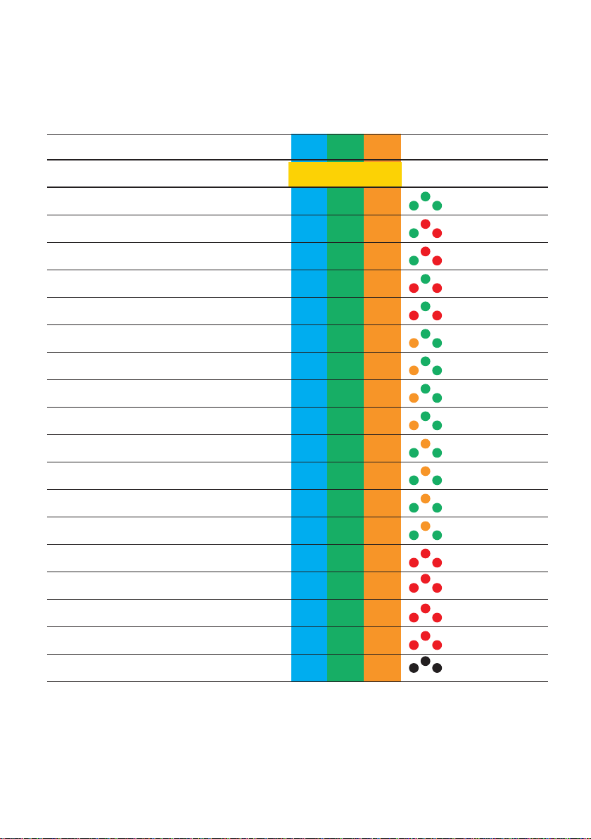
connected to the correct terminals on the back of the socket. If all three
LED’s light GREEN and no sound is emitted the wiring status is correct and
you can proceed to the incoming supply polarity test (step 3).
A fault with the socket wiring will be indicated by an audible alternating
tone and the LED’s, at least one of which will be Red or Orange, will flash.
If a fault indication is given – DO NOT PROCEED -investigation and
remedial action is required before you can conduct anRCD test.
If this happens placing your thumb on the polarity test pad will now activate
the ‘fault location’ function. With your thumb on the pad check the indication
given by the LED’s against the chart on the back cover to identify where the
main problem lies. Note: The colour of the LED’s may change when the pad
is touched.
3. Check that the mains voltage is in the correct range 207-253VAC.
Note: All tests are inhibited until the mains voltage appears in the display
4. Incoming supply Polarity Test - this important test is discussed in full
on page three of this manual, please read.
To conduct the test - with all three LED’s lit GREEN place your thumb on the
polarity test pad area. If the supply polarity is correct the LED's will start to
flash Green and you can proceed to step 4. If the supply polarity has been
reversed the three LED’s will turn Red and flash.
If this happens stop testing and notify the supply company immediately.
5. RCD TYPE SELECTION BUTTON
This selects the type and rating of RCD to be tested. 30mA, 100mA, 300mA
or 500mA rated type AC ( general purpose RCD's) and 100A or 300mA rated
type ACS (Selective)
6. SELECT TEST BUTTON
6a. CURRENT MULTIPLIER
This button is used to select the test current multiplier that is applied to the
selected rating of RCD type (chosen in step 5) for the test to be carried out.
For example if the 30mA rating was selected in step 5, choosing x1/2 here
would apply a test current current of 15mA (1/2 x 30mA) when the test is
conducted.
Choosing x5 here would apply a test current of 150mA (5x 30mA)

RCD testing
The multipliers available are:
x 1/2, x 1, x 2 and x 5 for 30mA and 100mA AC type RCD's
x 1/2 and x 1 for 300mA & 500mA type AC RCD’s and 100mA & 300mA
type ACS RCD's
Additionally the Ramp test function (see below) is available for all but the
500mA setting.
6B RAMP TEST
The SELECT TEST button is also used to access the Ramp test function.
This is a particularly useful diagnostic function that enables the fault current
applied to be started at just 3mA and raised automatically in small
increments. By doing this you can determine the amount of extra leakage it
is necessary to introduce into a circuit to trip the breaker. The result
displayed, unlike all of the other tests, will be the current rather than the
time taken to open the RCD.
7
Important note: You will see above that the x2 multiplier is available for
use with the 30mA or 100mA type AC setting. Where available, its
selection is indicated in the display by the x1 symbol flashing.
If, when selecting the test to be carried out the x1 symbol shows
continuously lit then the test will be conducted at the current rating
selected at step 5 (x1).
If the x1 symbol is flashing the test will be conducted at twice the current
rating selected (x2). ie. At the 30mA setting a 60mA test current will be
used.
The x2 setting is accessed by pressing the SELECT TEST button until
the multiplier cycles past the ramp test and the x1 symbol flashes.
When the test result is displayed the multiplier will show as x1
continuously lit regardless of whether the test was conducted at x1 or x2

RCD testing
7. POLARITY BUTTON
In manual mode this toggles between 0º phase angle and
180º phase angle.
In a 50Hz supply each full cycle of the A.C. supply will take 20 milliseconds
to complete. The speed with which many RCD’s will react varies depending
upon whereabouts within this cycle a fault is introduced; it is therefore
necessary to be able to introduce the fault at different points in the cycle to
ensure that the maximum disconnection time is identified.
The POLARITY switch enables the tests to be initiated at the start of both
the positive and negative half cycles. Differences of up 10ms are not
unusual.
8. AUTO BUTTON
The DRC430 defaults to manual operation upon powering on and in this
mode you control the test with the selections made in step 5
(Type/Rating),step 6 (Multiplier) & step 7 (polarity). A single press of the
test button will now initiate the test and display the result.
This is fine for occasional testing but a full test of each RCD will involve 6
separate tests for a 30mA breaker. Comprising testing at its rated current
(I∆n), at 5x (I∆n) and at ½ x(I∆n), with each test being conducted at both
0º and 180º. Four of these 6 tests should require the RCD to be reset, this
where the AUTO test function will save time and effort.
To use the AUTO function follow the above through to step 5 and select
the RCD rating and type. Then instead of selecting the multiplier at step 6,
simply press the AUTO button. Confirmation of auto mode is given in the
display window (see F page 5).
A single press of the test button will now automatically select the
appropriate multiplier and polarity for each test and run the full test
sequence for you – all you have to do is reset the breaker each time it trips.
As soon as the RCD is reset the tester recognises that power has been
restored and automatically conducts the next test in the sequence.
Upon returning to the tester pressing the recall button displays the results
in sequence of each test conducted. The LCD display changes to show
which test the result refers to and an audible tone is given to alert you of
any failures.
8

RCD testing
The same procedure is used for RCD’s with a rating higher than 30mA but
the two tests at 5x the rated current are not required for these.
Example for a 30mA RCD
Select 30mA by pressing the RCD∆/ TYPE button until 30mA is
displayed.
Press AUTO button - the display should now show x1 30mA AUTO (as
well as the voltage)
Press test button 9
A 30mA test will be carried out and the result displayed.
As soon as the breaker is reset the display will change from to
to indicate that the next test will at 180º phase angle, the test will
automatically be conducted and the result displayed.
As soon as the breaker is reset the display will change from to
and from x1 to x5 to indicate that the next test will be at 0º phase
angle, at 150mA (5x 30mA). The test will automatically be conducted and
the result displayed.
As soon as the breaker is reset the display will change from to
to indicate that the next test will be at 180º phase angle, the test will
automatically be conducted and the result displayed.
When the breaker is reset the display will change from x5 to x ½
and from to to indicate that the next test will be at 15mA
(1/2 x 30mA) and at 0º phase angle and the test will run.
The display should now show >2.00s to indicate that the RCD did not trip
within 2 seconds when tested at ½ of its rated current.
The tester will automatically repeat this test at 180º phase angle and if all is
well will display the same >2.00s reading.
The auto test sequence is now complete and the results can be recalled by
using the recall button.
9


11
Features
Type AC & ACS breakers
30mA breakers x1/2, x1, x2, x5 test currents
100mA, 300mA, 500mA breakers x1/2, x1 test currents
Unlimited number of RCD tests
RCD test polarity change
Auto / Manual test on all breakers
Full socket test and mains polarity test
Complies with EN61557 parts 1 and 6 (performance)
Complies with EN61010 (safety)
Complies with EN61326 (EMC)
RCD Test Range (to EN61557-6)
Supply voltage 195V – 253V AC 50Hz
Test current accuracy (1/2 I) –0% to –10%
Test current accuracy (I, 5I) +0% to +10%
Trip time accuracy Up to 1 second +/-(1% + 1ms)
Over 1 second +/-(1% +10ms)
Voltage measurement
Range 5V to 440V +/-(2% + 1V) over the working frequency range of 50Hz +/-0.5%
Socket test
Detects opens, shorts, wrong wiring, phantom conditions, phase reversal, out of limits voltage.
Fault Touch Voltage
Test terminated if >25V
Power
4 x AA batteries ‘Alkaline’ recommended
Battery life 10,000 tests
Fitted fuse 32mm 0.25A (F) HBC
Survives 440V over voltage test rated for 1 minute.
Environmental
Operating Temperature Range . . . . . . . . . . . . . . . . . . . . . . . . . . . . . . . . . . . . . . . . 0˚C to 40˚C
Storage Temperature Range . . . . . . . . . . . . . . . . . . . . . . . . . . . . . . . . . . . . . . . -10˚C to +60˚C
Operating Humidity . . . . . . . . . . . . . . . . . . . . . . . . . . . . . . . . . . . . . . . . . . . . 93% RH @ 40˚C
Size . . . . . . . . . . . . . . . . . . . . . . . . . . . . . . . . . . . . . . . . . . . . . . . . . .157mm x 89mm x 39mm
Weight . . . . . . . . . . . . . . . . . . . . . . . . . . . . . . . . . . . . . . . . . . . . . . . . . . . . . . . . . . . . . . . .400g
Specications
Socket & See Industrial
www.socketandsee.co.uk
Unit 4, Century Road,High Carr Business Park,
Newcastle, Staffordshire, UK, ST5 7UG
T +44 (0)1782 567096
F +44 (0)1782 567095

Condition Wiring Supply LED Buzzer
Number Condition Terminal Display
NEL
Socket Wiring
1 Correct NEL Continuous
2 L-E reverse NLE Warble
3 L-N-E miswire ELN Warble
4 L-N reverse LEN Warble
5 L-N-E miswire LNE Warble
6 Faulty N / L-E miswire NC L N Warble
7 Faulty N / E miswire NC N L Warble
8 Faulty N NC E L Warble
9 Faulty N / L-E reverse NC L E Warble
10 Faulty E / L-N reverse LNCN Warble
11 Faulty E NNCL Warble
12 Faulty E / N miswire ENCL Warble
13 Faulty E / L-N miswire LNCE Warble
14 Faulty L / N-E miswire LNNC Warble
15 Faulty L / E miswire NLNC Warble
16 Faulty L / N-E miswire ELNC Warble
17 Faulty L / N miswire LENC Warble
18 No Mains NC NC NC None
Above is the indication given when touching the touch pad
LED’s will flash to indicate fault condition NC=No Connection
Table of contents
Other Socket & See Test Equipment manuals

Socket & See
Socket & See SP200 User manual

Socket & See
Socket & See VIP ESI User manual

Socket & See
Socket & See MFT5000 User manual

Socket & See
Socket & See PDIT 360 User manual

Socket & See
Socket & See DIT 400 User manual

Socket & See
Socket & See RCD PRO User manual

Socket & See
Socket & See PDL 234Plus User manual

Socket & See
Socket & See FFCB 100 User manual

Socket & See
Socket & See PDL 310 User manual

Socket & See
Socket & See PDL PRO User manual