6PW20i
HBM A1269-2.0 en/de/fr
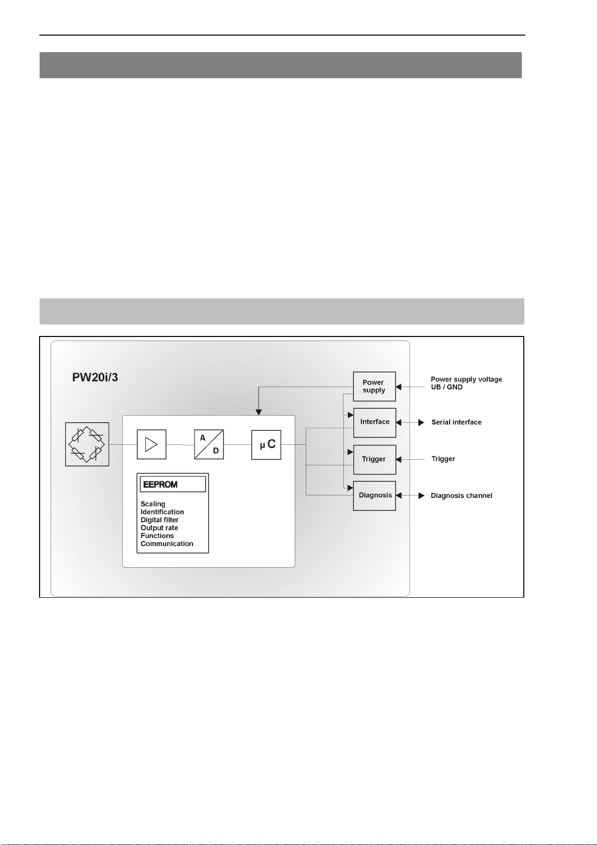
1 Application
The PW20i load cells belong to the digital load cells and measurement chain
family specially developed by HBM for high-speed dynamic weighing
processes. They acquire measurement signals from strain gages, condition
them digitally, output them and can network them for buses on request.
They supply a fully-filtered, scaled and digitalized output signal for direct
connection to a bus system or a PC. They operate with high sampling rates of
up to 1200 measurements per second and can be easily and rapidly adapted
to the actual weighing system by means of adjustable parameters.
The integrated trigger function allows event-driven weight determination which
significantly reduces the external software requirements for checkweigher
applications, for example.
The PW20i includes dosing control. As this load cell does not have any digital
outputs, the external Master control must make digital I/Os available. The
PW20i generates the information to control these digital outputs in the
respective measurement statuses (MSV - measurement status). The Master
control then only needs to forward these control bits to its digital outputs, in
order to drive the dosing control valves.
The load cell can be delivered with RS-485, RS-232, CANopen or DeviceNet
interface options.
PW20i load cells are space-saving in use and are protected against spray
water and contamination by a stainless steel casing (IP 65).
The PC software AED_Panel32 is available to facilitate parameter settings, to
display dynamic measurement signals and for comprehensive frequency
analysis of the dynamic system.
This part of the operating instructions describes the hardware and the functions
of the PW20i digital load cells. In the help file “AED_help_e” you will find the
commands for serial communication.