MTS Sensors MH Series User manual

The MH-Series Analog/PWM Tester supports analog, 4 - 20 mA and 0 - 10 Vdc,
scaled Pulse Width Modulated (PWM), and PWM time of flight (tOF) sensor
outputs. The MH-Series tester is a battery powered device that is be used in test
bench and field applications to verify that the MTS Sensor is functioning properly
and is producing the appropriate signal outputs.
FEATURES:
Easy connection to MTS’ M12 integrated connector system
Easy to use push-button controls
Supports voltage (0-10 Vdc) and current (4-20 mA) outputs
Supports scaled PWM and time-of-ight PWM outputs
Compact construction for use in eld applications
Provides both +5 Vdc and +12Vdc sensor power supply
Sealed lead acid battery that provides up to 8 hours of operation per
charge
Battery level monitoring
Automatic detection of PWM sensor frequency
Carrying case
All specifications are subject to change. Contact MTS for specifications and engineering
drawings that are critical to your application. Drawings contained in this document are for
reference only. Go to www.mtssensors.com for the latest support documentation.
Temposonics
®
Magnetostrictive
Linear-Position Sensors
User’s Guide
551132 B
MH-Series Analog / PWM Tester

MH-Series Analog / PWM Test Kit - User’s Guide (Part No. 551132B) MTS Sensors
Contents
Section 1.0 The MH-Series Analog / PWM Test Kit
1.1 Contents and accessories............................................... 3
1.2 Familiarizing yourself with the MH-Series tester .........4
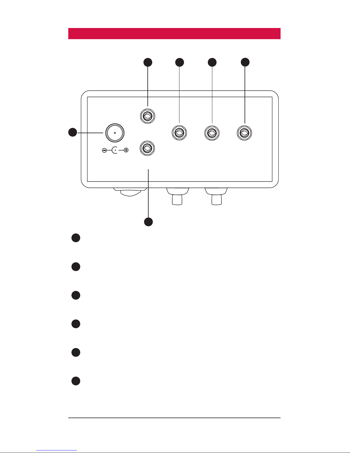
1.2.1 Front panel ...........................................................4
1.2.2 Top panel .............................................................5
Section 2.0 Installation
2.1 Connecting analog sensors............................................ 6
2.2 Connecting PWM Sensors ............................................. 7
2.3 SLA battery charger setup.............................................. 8
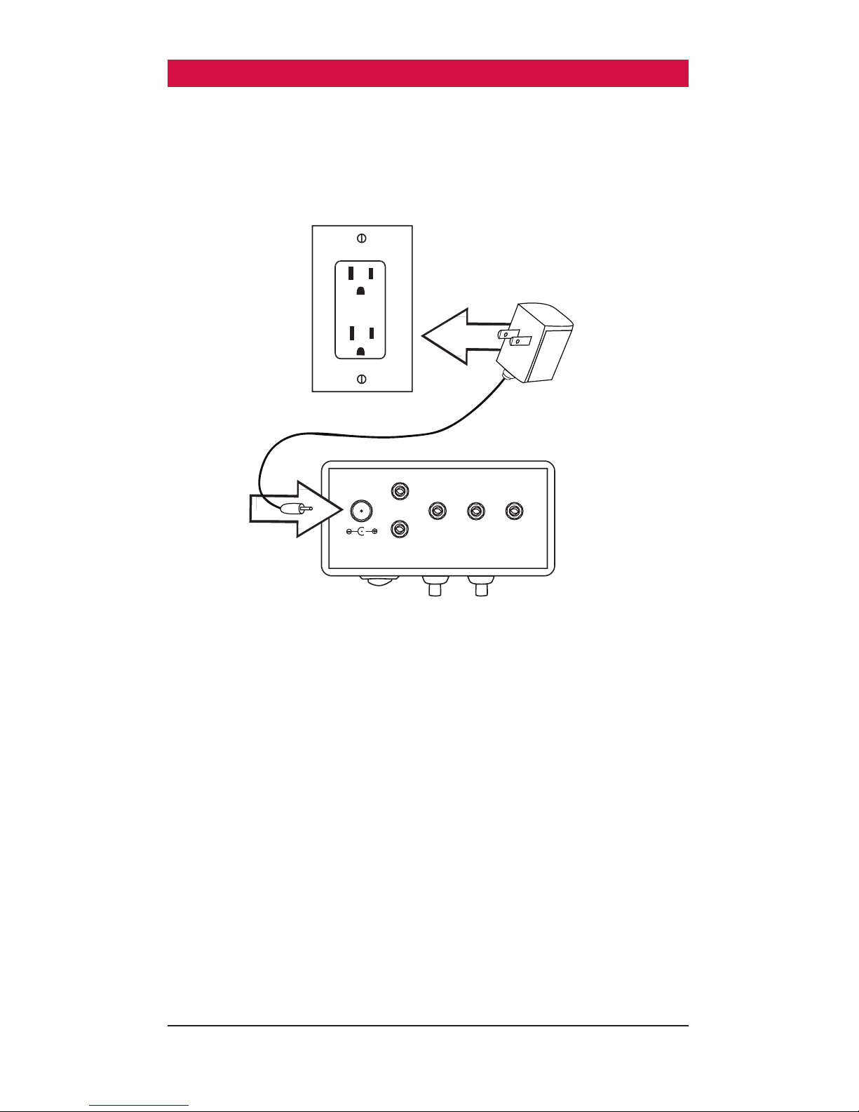
2.4 AC Power plug adapter connection / replacement.......... 8
2.5 Quick start instruction label ........................................ 10
Section 3.0 Operation
3.1 Startup .........................................................................11
3.2 Mode selections........................................................... 12
3.2.1 Voltage (Volt) .........................................................12
3.2.2 Current (Curr) ........................................................12
3.2.3 Battery level (Batt)................................................. 12
3.2.4 Battery charging ....................................................13
3.2.5 Scaled PWM (Puum) ............................................ 14
3.2.6 Time of Flight PWM .............................................. 15
3.3 Verification .................................................................. 17
3.4 Troubleshooting ...........................................................17
Contact and Support Information
2
General:
Tel: (919) 677-0100
Fax: (919) 677-0200
E-mail: [email protected]
http://www.mtssensors.com
Mailing and Shipping Address:
MTS Systems Corporation
Sensors Division
3001 Sheldon Dr.
Cary, NC USA 27513
Customer Service:
Tel: (800) 633-7609
Fax: (800) 498-4442
Office Hours (EST):
Monday - Thursday:
8:00 a.m. to 5:00 p.m.
Friday: 8:00 a.m. to 4:00 p.m.
Quote and Contract Terms & Conditions:
The parties expressly agree that the
purchase and use of Material and/or
Services from MTS Sensors Division are
subject to MTS’ Terms and Conditions,
in effect as of the date of this document,
which are located at http://www.
mtssensors.com/fileadmin/media/pdfs/
Terms_and_Conditions.pdf and are
incorporated by reference into this and
any ensuing contract. Printed Terms and
Conditions can be provided upon request
you prefer, go to http://www.mtssensors.
com/index and click the Quote/Contract
Terms and Conditions link at the bottom
of the page to download the PDF.
Related publications:
Product Specification, MH-Series Analog /
PWM Test Kit, Part no. 551139. Download
the (PDF) http://www.mtssensors.com.

MTS Sensors MH-Series Analog / PWM Test Kit - User’s Guide (Part No. 551132B)
1.0 - The MH-Series Analog / PWM Test Kit
1.1 Contents and Accessories
The MH-Series Analog / PWM Test Kit includes:
1
MH-Series Analog / PWM Tester
2
12 Vdc Sealed Lead Acid (SLA) battery charger with adapter
3
Cable with MTS’ M12 integrated connector system and banana plugs
4
Pigtailed cable with banana plugs
5
Carrying case (part no. 561924)
6
User’s Guide (part no. 551132, not pictured)
7
Quick start instruction label (part no. 551656, not pictured)
Power Plug Adapter,
North America
Power Plug Adapter,
European Union
Power Plug Adapter,
United Kingdom
AB
POWER
www.mtssensors.com
3
1
2
3
5
4

MH-Series Analog / PWM Test Kit - User’s Guide (Part No. 551132B) MTS Sensors
1.0 - The MH-Series Analog / PWM Test Kit (continued)
1.2 Familiarizing yourself with the MH-Series Tester
1.2.1 Front panel
1
LCD panel
Tester LCD panel displays sensor output, settings, and battery level
2
Power switch
Toggle to turn the MH-Series Tester ‘ON’ and ‘OFF’
3
Mode button ‘A’
Press to change transducer modes and to reset system
4
Special function button ‘B’
Press to change recirculation values in PWM / tOF mode and to reset
system
3
4
1
2
AB
POWER
www.mtssensors.com
AB
POWER
4

MTS Sensors MH-Series Analog / PWM Test Kit - User’s Guide (Part No. 551132B)
1.0 - The MH-Series Analog / PWM Test Kit (continued)
1.2.2 Top panel
1
Charger port
Port used to charge the internal SLA battery
2
+5 Vdc port
Sensor 5 volt supply connection (Not an input port)
3
+12 Vdc port
Sensor 12 volt supply connection (Not an input port)
4
GND
Sensor ground connection
5
Analog port
0-10 Vdc or 4-20 mA sensor output connection
6
PWM port
PWM (Scaled) or PWM (tOF) sensor output connection
1
2
4
5
6
−
+
−
+
+5V
PWM
ANA
GND
+12V
3
5

MH-Series Analog / PWM Test Kit - User’s Guide (Part No. 551132B) MTS Sensors
2.0 Installation
2.1 Connecting an analog sensor
To connect an Analog sensor equipped with MTS’ M12 integrated connector
system to the MH-Series Tester use the following procedure:
1. Use the provided cabling fitted with the M12 connector
and connect the M12 cable to the MTS M12 integrated connector
system on the sensor or cylinder. (continue with step 3 below) OR
To connect an Analog Sensor not equipped with MTS’ M12 integrated connector
system:
1. Use the Pigtailed cable that is included in the test kit to connect the ends
without banana plugs to the customer’s specified interface/connector
that mates to the MH-Series Sensor or cylinder.
2. Ensure that the wire colors of the cable correspond with the wire colors
of the output wires from the sensor.
3. Plug the brown banana plug into the +12 Vdc or +5 Vdc (depending on
voltage required by the sensor) terminal on the top of the tester.
4. Plug the white banana plug into the DC GND terminal on the top of
the tester.
5. Plug the green banana plug into the analog terminal at the top of
the tester.
−
+
−
+
+5V
PWM
ANA
GND
+12V
Green
White
Brown
M12 Cable Assembly
Select sensor
supply voltage
(+12V or +5V)
Select sensor
supply voltage
(+12V or +5V)
CUSTOMER
SPECIFIED
INTERFACE/
CONNECTOR
−
+
−
+
+5V
PWM
ANA
GND
+12V
White
Green
Brown
White
Green
Brown
White
Green
Brown
Sensor cable
Pigtail cable
assembly
6

MTS Sensors MH-Series Analog / PWM Test Kit - User’s Guide (Part No. 551132B)
2.0 Installation (continued)
2.2 Connecting PWM Sensors
To connect a PWM sensor equipped with MTS’ M12 integrated connector system
to the MH-Series Tester use the following procedure:
1. Use the provided cabling fitted with the M12 connector
and connect the M12 cable to the MTS M12 integrated connector
system on the sensor or cylinder. (continue with step 3 below) OR
To connect a PWM Sensor not equipped with MTS’ M12 integrated connector
system:
1. Use the Pigtailed cable that is included in the test kit to connect the ends
without banana plugs to the customer’s specified interface/connector
that mates to the MH-Series Sensor or cylinder.
2. Ensure that the wire colors of the cable correspond with the wire colors
of the output wires from the sensor.
3. Plug the brown banana plug into the +12 Vdc terminal on the top of the
tester.
4. Plug the white banana plug into the DC GND terminal on the top of
the tester.
5. Plug the green banana plug into the PWM terminal at the top of
the tester.
−
+
−
+
+5V
PWM
ANA
GND
+12V
Green
White
Brown
M12 Cable Assembly
Select sensor
supply voltage
(+12V or +5V)
Select sensor
supply voltage
(+12V or +5V)
CUSTOMER
SPECIFIED
INTERFACE/
CONNECTOR
−
+
−
+
+5V
PWM
ANA
GND
+12V
White
Green
Brown
White
Green
Brown
White
Green
Brown
Sensor cable
Pigtail cable
assembly
7

MH-Series Analog / PWM Test Kit - User’s Guide (Part No. 551132B) MTS Sensors
2.0 Installation (continued)
2.3 SLA battery charger setup
The MH-Series tester will also run off of AC power supplied by the charger
included in the Test Kit. To run the box off of AC power or to charge the internal
SLA battery plug the charger barrel plug into the charger port on the top of the
Test Box and connect the charger to an AC outlet.
2.4 AC power plug adapter connection / replacement
The kits SLA Battery charger rating is based on a nominal input of 90-264
Vac/47-63 Hz and can be used on both 110 Vdc and 240 Vdc systems. For this
reason, additional AC power plug adapters are included.
Use the following steps to change the power plug adapter:
1. Unplug the AC adapter from the wall and from the MH-Series Tester.
Firmly hold the AC adapter in one hand with the plug facing you.
2. With the other hand, press down on the plug adapter and slide upwards
away from you.
−
+
−
+
+5V
PWM
ANA
GND
+12V
8

MTS Sensors MH-Series Analog / PWM Test Kit - User’s Guide (Part No. 551132B)
2.0 Installation (continued)
To replace the AC power plug adapter:
1. Hold the AC adapter in one hand
2. With the other hand slide the adapter plug against the adapter
(There are grooves along the channel for the adapter plug)
3. Slide the adapter plug down until it snaps into place.
Notes:
There is an arrow on the adapter to denote the way to slide the plug during removal.
9
2.5 Quick start instruction label
A quick start instruction label is included in the test kit. The label is designed to
fit flush on the MH-Series Analog / PWM tester.
1. Remove backing from the quick start label.
2. Align the label to either the front or back of the tester and apply the
label smoothly.

MH-Series Analog / PWM Test Kit - User’s Guide (Part No. 551132B) MTS Sensors
3.0 Operation
3.1 Startup
Notes
1. The tester switch is in the ‘ON’ position when the Red LED is lit.
2. If the LED on the power switch is not lit, the device might be in low power mode and
the power supply needs to be connected to the charger port on the top of the tester.
3. If testing the sensor on the bench, place the magnet on the sensor prior to powering
up the MH-Series Tester.
Perform the following start-up procedure:
1. Turn the tester power switch to the ‘ON’ position. The test box display
will now cycle through the startup display sequence:
a. LED test for 1 second.
b. Software Data test for 1 second
c. Sensor type test for 5 seconds or until the ‘A’ button is pressed.
The default mode setting is configured for voltage at the factory, but
after its initial use, the tester will start up in the last mode the tester was set
to.
2. If required, change the mode by pushing the ‘A’ button.
(see 3.2 Mode Selections)
3. Repeat step 2 until the appropriate mode is selected and seen on the
display.
3.2 Mode Selections
Mode Display Units
Voltage Volt Volts
Current Curr Milliamps (mA)
Battery bAtt Displays SLA battery
voltage (Volts)
Scaled PWM Puum % of Displacement
Time-Of-Flight PWM tOF Millimeters (mm)
3.2.1 Voltage (Volt)
The voltage range between 0 and 10 Vdc will be displayed for the MH-Series
sensor with voltage output. The voltage range shown will be dependent on the
sensor model selected.
10

MTS Sensors MH-Series Analog / PWM Test Kit - User’s Guide (Part No. 551132B)
3.0 Operation (continued)
3.2.2 Current (Curr)
The current range between 4 and 20 mA will be displayed for the MH-Series
sensor with current output. The current range shown will be dependent on the
sensor model selected.
3.2.3 Battery Level (Batt)
Notes:
1. See sensor model specification to determine what supply voltage is needed.
2. The LOBA (Low Battery) status alert will disrupt the output readings of the sensor
every 60 seconds for 3 seconds until the power adapter is connected to the tester
via the charger port.
The MH-Series Tester utilizes a Sealed Lead Acid (SLA) battery to power both the
tester and the sensor. The MH-Series Tester contains circuitry that continually
measures the device battery level to ensure that the necessary voltage is avail-
able to power the sensor. If the battery level drops below 9 volts, the tester will
not have enough power to energize most MH-Series sensors. Some MH-Series
model sensors only require a 5 volt supply and for these transducers test box
battery voltage levels lower than 5 volts will interrupt sensor output.
Low battery (LOBA)
If ‘LOBA’ (Low Battery) displays, connect the 12 volt power adapter to the charger
port. Whenever the internal SLA battery is allowed to discharge below 1.8 volts,
the device will enter low power mode. In the event the device enters low power
mode, connect the supply voltage to the charger port and cycle the power. When
the battery level drops below 1.8 volts there is not enough voltage to drive the
internal circuitry of the MH-Series Tester.
3.2.4 Battery Charging
WARNING
Only use the supplied 12 volt adapter to charge the MH-Series Tester. Using an off
the shelf AC adapter without smart charging capabilities can result in overcharging
the internal Sealed Lead Acid (SLA) batteries. Overcharging the batteries could lead
to overheating and damage to the battery cells.
To recharge the internal batteries of the MH-Series Tester, connect the supplied
AC power plug adapter to the charger port on the top of the device. The LED
11

MH-Series Analog / PWM Test Kit - User’s Guide (Part No. 551132B) MTS Sensors
indicator on the charger will indicate the state of the charging process. The
smart charger that is included in the MH-Series Tester Kit will give the SLA
battery a quick charge first and then apply a constant float charge to maintain
battery level.
3.24 Scaled PWM (PWM)
Configuring the MH-Series Tester to PWM mode will allow for the output of a
scaled PWM sensor to be displayed.
The MH-Series Tester will initially show the frequency of the attached scaled
PWM sensor output. This will be displayed for 2 seconds before switching the
display to the sensor output range.
The scaled PWM sensor output will display the sensor position as a % of the
output frequency. At the zero position the z% for the attached sensor will be
displayed. At the full stroke position the fs% for the attached sensor will be
displayed. The sensor output for each position in between the zero position and
the full stroke position will displayed as a percentage of stroke over the available
range of z% to fs%.
Example Readings for Various Sensor Types:
PWM Sensor
Type
% at Zero
Position
(z%)
% at 1/4
stroke
% at
1/2
stroke
% at
3/4
stroke
% at
full
stroke
(fs%)
5% - 95% 5% 27.5% 50% 72.5% 95%
10% - 90% 10% 30% 50% 70% 90%
15% - 85% 15% 32.5% 50% 67.5% 85%
20% - 80% 20% 35% 50% 65% 80%
25% - 75% 25% 37.5% 50% 62.5% 75%
To view the frequency of the scaled PWM sensor:
1. Press the ‘B’ button once
2. Frequency will display for 2 seconds
3. Repeat as needed
12
3.0 Operation (continued)

MTS Sensors MH-Series Analog / PWM Test Kit - User’s Guide (Part No. 551132B)
3.2.5 PWM TOF (tOF)
PWM, time of flight Sensor
Time of Flight mode allows for the MH-Series Tester to display the output of a
PWM, TOF sensor. In a TOF sensor the displacement amount is determined by
the time between the creation of the interrogation pulse and the detection of
the return pulse in the sensing element. This TOF calculation is dependent on
the velocity of the return pulse, sensor length, and the number of recirculations
performed by the sensor. In TOF mode the position output is displayed in mil-
limeters.
Note:
In order to display millimeters a fixed value has been used for the location of the null
with respect to the sensing element. The MH-Series Tester is set up for the standard
offset in the Model MH and MS sensors. For all other models there may be a shift
in the output reading due to mechanical differences from the MH and MS models.
Please check with the factory for the offset on other MH-Series sensor models.
Recirculations
When the MH-Series tester is in TOF mode, the tOF name on the display is fol-
lowed by a character (Hex Value: 0-F) which indicates the number of recirculations
expected from the attached sensor. The default recirculation character for the
mode is 0. The number of recirculation can be changed to accommodate the
attached sensor output.
Perform the steps below to reset the number of recirculations:
1. When ‘tOF’ displays on the screen, press and hold the ‘B’ button for
2 seconds
2. The recirculation character (0-F) will begin to blink.
3. When the character is blinking:
Press the ‘B’ button to change the value. Repeat the procecedure until
the appropriate value displays. Then, press the ‘A’ button to return to
‘tOF’ measurement mode.
14
3.0 Operation (continued)
Note:
Once the ‘A’ button is pressed the desired recirculation value is saved in the memory.

MH-Series Analog / PWM Test Kit - User’s Guide (Part No. 551132B) MTS Sensors
Display Value Recirculations
t0F0 0
t0F1 1
t0F2 2
t0F3 3
t0F4 4
t0F5 5
t0F6 6
t0F7 7
t0F8 8
t0F9 9
t0FA 10
t0Fb 11
t0FC 12
t0Fd 13
t0FE 14
t0FF 15
Notes:
1. ‘t0F0’denotes that there are no recirculations only the initial interrogation pulse.
2. In the PWM TOF mode if the reported displacement is longer than 4 digits the
display will blink and only the most significant digits will be displayed.
3.0 Operation (continued)
15

MTS Sensors MH-Series Analog / PWM Test Kit - User’s Guide (Part No. 551132B)
15
3.0 Operation (continued)
3.3 Verification
Verify the sensor is reading the displacement of the magnet by moving the mag-
net in a bench test of the attached sensor or by stroking the cylinder. Observe
the change in output reading.
Note:
The MH-Series Tester is not a calibrated device and should only be used for indica-
tion purposes only. The MH-Series Tester is designed to be used to verify that the
sensor is functional after cylinder assembly and as a field troubleshooting device.
For field troubleshooting the tester is designed to isolate the sensor from the rest of
the vehicle in order to independently verify sensor functionality.
3.4 Troubleshooting
No Power
1. Confirm that Power switch is in “ON” position
2. MH-Series Tester may be in Low Power Mode
3. Plug in AC power adapter and check the battery level
The sensor readings aren’t showing on the display
1. Is the MH-Series Tester in the correct mode?
2. Is the MH-Series battery level above 9 Vdc (5 Vdc for 5V sensor)?
3. Is the sensor connected to the appropriate terminals.
Error Message “[--]” is seen in PWM or TOF Mode
1. Make sure the correct plug is in the PWM port at the top of the MH-Series
Tester
2. If in tOF mode, make sure the correct number or recirculations is
selected
3. Check battery level to ensure the unit is providing a minimum of 9 Vdc
to sensor (5 Vdc for 5V sensor).

MH-Series Analog / PWM Test Kit - User’s Guide (Part No. 551132B) MTS Sensors
3.0 Notes
16

MTS Sensors MH-Series Analog / PWM Test Kit - User’s Guide (Part No. 551132B)
Notes:
18

MH-Series Analog / PWM Test Kit - User’s Guide (Part No. 551132B) MTS Sensors
Notes:
19

UNITED STATES
MTS Systems Corporation
Sensors Division
3001 Sheldon Drive
Cary, NC 27513
Tel: (800) 633-7609
Fax: (919) 677-0200
(800) 498-4442
www.mtssensors.com
GERMANY
MTS Sensor Technologie
GmbH & Co. KG
Auf dem Schüffel 9
D - 58513 Lüdenscheid
Tel: +49 / 23 51 / 95 87-0
Fax: +49 / 23 51 / 56 491
www.mtssensors.com
Part Number: 551132 Revision B (EN) 07/2015
MTS and Temposonics, and are registered trademarks of MTS Systems Corporation.
All other trademarks are the property of their respective owners.
All Temposonics sensors are covered by US patent number 5,545,984. Additional patents are pending.
Printed in USA. Copyright © 2015 MTS Systems Corporation. All Rights Reserved in all media.
JAPAN
MTS Sensors Technology
Corporation
737 Aihara-cho, Machida-shi
Tokyo 194-0211, Japan
Tel: +81-42-775-3838
Fax: +81-42-775-5516
www.mtssensors.com
Table of contents