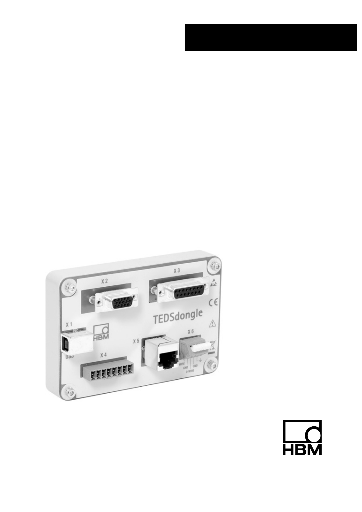
HBM TEDSdongle User manual

A2869−1.2 en/de
TEDS PC adapter
Operating manual
TEDSdongle
Bedienungsanleitung
TEDS−PC−Adapter


3
TEDSdongle
HBMA2869−1.2 en/de
Contents Page
Safety information B-4. . . . . . . . . . . . . . . . . . . . . . . . . . . . . . . . . . . . . . . . . . . . . .
1 Introduction B-8. . . . . . . . . . . . . . . . . . . . . . . . . . . . . . . . . . . . . . . . . . . . . . . . .
1.1 Scope of supply and accessories B-8. . . . . . . . . . . . . . . . . . . . . . . . . .
1.2 General Information B-8. . . . . . . . . . . . . . . . . . . . . . . . . . . . . . . . . . . . . .
2 Electrical connection B-11. . . . . . . . . . . . . . . . . . . . . . . . . . . . . . . . . . . . . . . .
2.1 Attaching the ferrite element B-11. . . . . . . . . . . . . . . . . . . . . . . . . . . . . .
2.2 Pin assignment B-12. . . . . . . . . . . . . . . . . . . . . . . . . . . . . . . . . . . . . . . . . .
3 Starting up B-14. . . . . . . . . . . . . . . . . . . . . . . . . . . . . . . . . . . . . . . . . . . . . . . . . .
3.1 Operation with the TEDS Editor B-15. . . . . . . . . . . . . . . . . . . . . . . . . . . .
3.2 Using the TEDS Editor B-16. . . . . . . . . . . . . . . . . . . . . . . . . . . . . . . . . . .
3.2.1 Editing TEDS in the HBM view B-17. . . . . . . . . . . . . . . . . . . . . .
3.2.2 Editing TEDS in the Template view B-18. . . . . . . . . . . . . . . . . . .
4 Dimensions B-19. . . . . . . . . . . . . . . . . . . . . . . . . . . . . . . . . . . . . . . . . . . . . . . . .

4TEDSdongle
A2869−1.2 en/deHBM
Safety information
Intended use
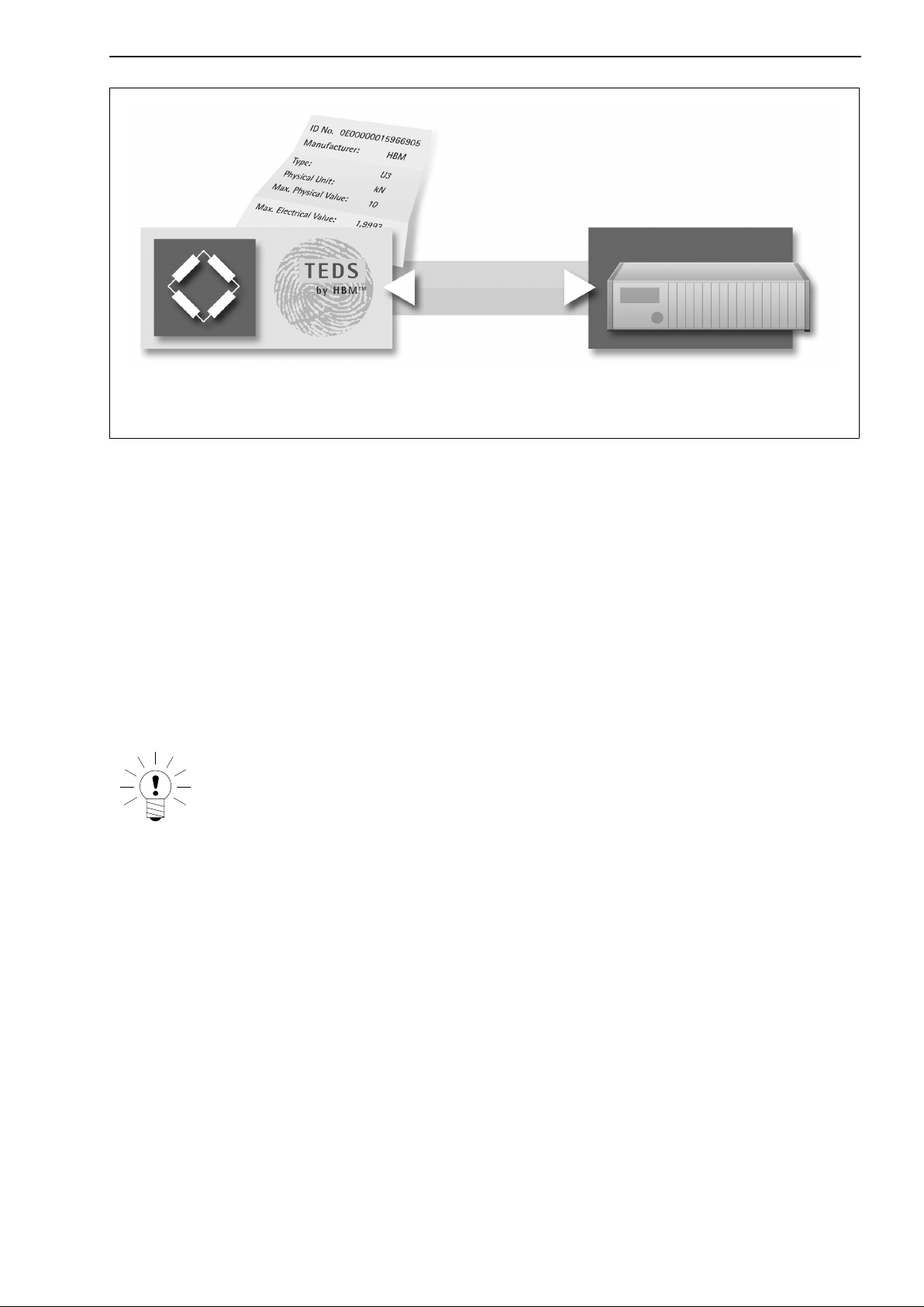
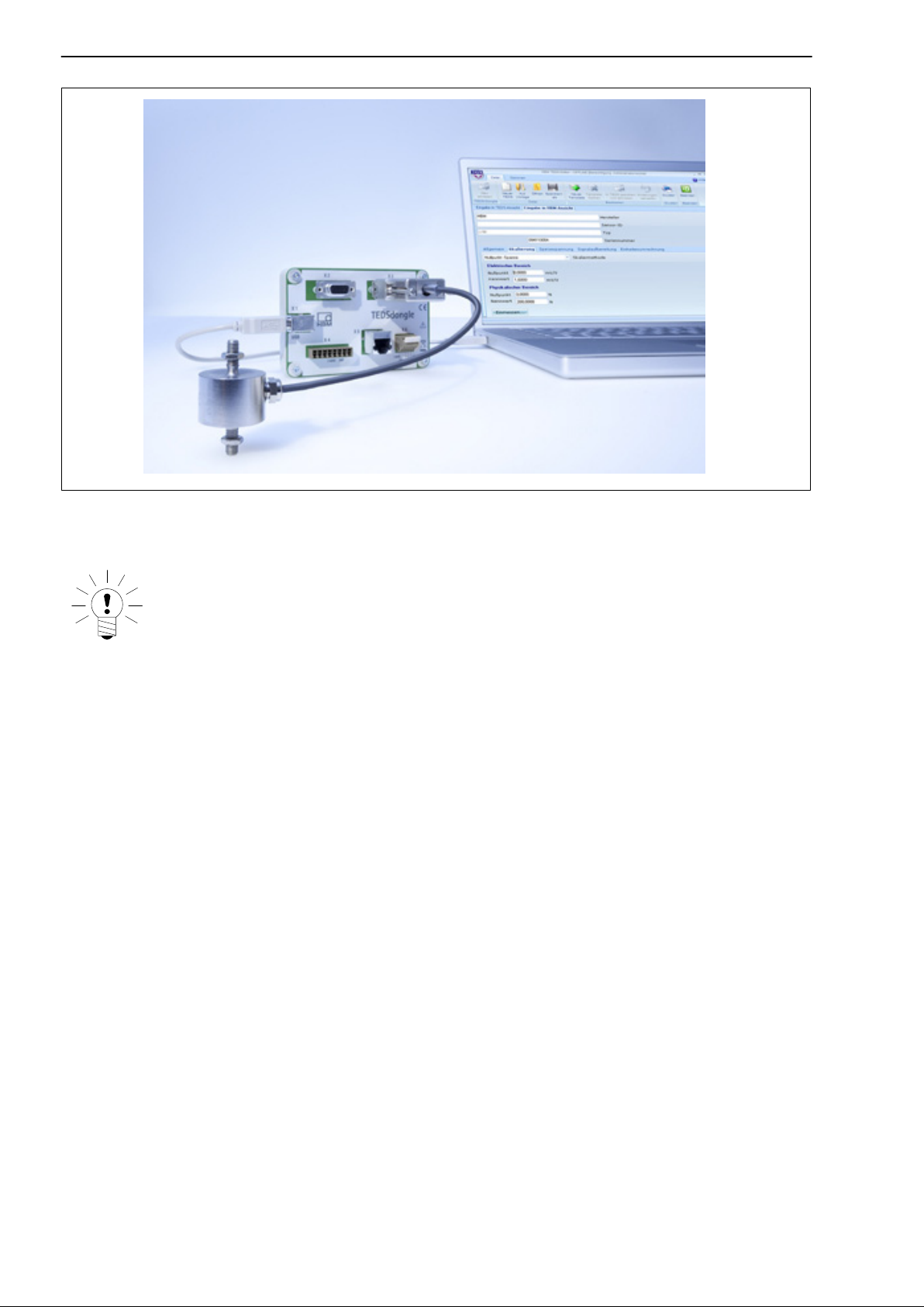
The TEDSdongle is to be used only as an accessory for TEDS storage
electronics for transducers in conjunction with suitable measuring amplifiers.
Use for any purpose other than the above is deemed to be inappropriate.
In the interests of safety, the module must only be fitted and operated as
specified in the Mounting Instructions. It is also necessary to observe the
regulations for operating the transducer and the amplifier respectively. It is
also essential to comply with the legal and safety requirements for the
application concerned during use.
General dangers of failing to follow the safety instructions
The TEDSdongle corresponds to the state of the art and is failsafe.
The module may give rise to dangers if it is inappropriately installed and
operated by untrained personnel.
Any person instructed to carry out installation, commissioning, maintenance or
repair of the device must have read and understood the Operating Manual
and in particular the technical safety instructions.
Residual risks
The scope of supply and performance of the TEDSdongle covers only a small
area of measurement technology. In addition, equipment planners, installers
and operators should plan, implement and respond to the safety engineering
considerations of measurement technology in such a way as to minimize
remaining dangers. Prevailing regulations must be complied with at all times.
There must be reference to the remaining dangers connected with
measurement technology.
After making settings and carrying out activities that are password-protected,
you must make sure that any controls that may be connected remain in safe
condition until the switching performance of the amplifier system has been
tested.

5
TEDSdongle
A2869−1.2 en/de HBM
Any risk of remaining dangers when working with the TEDSdongle is pointed
out in this manual by means of the following symbols:
Symbol: WARNING
Meaning: Dangerous situation
Warns of a potentially dangerous situation in which failure to comply with
safety requirements can lead to death or serious physical injury.
Symbol: CAUTION
Meaning: Possibly dangerous situation
Warns of a potentially dangerous situation in which failure to comply with
safety requirements could lead to damage to property and slight or moderate
physical injury.
Symbol: CAUTION
Meaning: Electrostatically sensitive components
Components marked with this symbol can be damaged beyond repair by
electrostatic discharge. Please observe the handling instructions for
components exposed to the risk of electrostatic discharge.
Symbols for application instructions and useful information:
Symbol: NOTE
Means that important information about the product or its handling is being
given.

6TEDSdongle
A2869−1.2 en/deHBM
Symbol:
Meaning: Statutory waste disposal mark
In accordance with national and local environmental protection and material
recovery and recycling regulations, old devices that can no longer be used
must be disposed of separately and not with normal household garbage. If
you need more information about waste disposal, please contact your local
authorities or the dealer from whom you purchased the product.
Symbol:
Meaning: CE mark
The CE mark enables the manufacturer to guarantee that the product
complies with the requirements of the relevant EC directives (the Declaration
of Conformity can be found at http://www.hbm.com/hbmdoc).
Working safely
Error messages should only be acknowledged once the cause of the error is
removed and no further danger exists.
Conversions and modifications
The TEDSdongle must not be modified from the design or safety engineering
point of view except with our express agreement. Any modification shall
exclude all liability on our part for any resultant damage.
In particular, any repair or soldering work on motherboards is prohibited.
Qualified personnel
Qualified persons means persons entrusted with the installation, fitting,
commissioning and operation of the product who possess the appropriate
qualifications for their function. This device is only to be installed and used by
qualified personnel, strictly in accordance with the specifications and the
safety rules and regulations.
This includes people who meet at least one of the three following
requirements:
•Knowledge of the safety concepts of automation technology is a
requirement and as project personnel, you must be familiar with these
concepts.

7
TEDSdongle
A2869−1.2 en/de HBM
•As automation plant operating personnel, you have been instructed how to
handle the machinery and are familiar with the operation of the equipment
and technologies described in this documentation.
•As commissioning engineers or service engineers, you have successfully
completed the training to qualify you to repair the automation systems. You
are also authorized to activate, ground and label circuits and equipment in
accordance with safety engineering standards.
It is also essential to comply with the legal and safety requirements for the
application concerned during use. The same applies to the use of
accessories.
Ferrite element
We recommend attaching the ferrite element, included in the scope of supply,
to the USB cable (connection to PC, see also Chap. 2.1) to improve EMC
performance.
EMC behavior
CAUTION
The TEDSdongle has been checked according to the valid EMC directive
2004/108/EC and meets equipment class A, industry standard.
If ESD interference effects over 5 kV occur, connection failures between the
TEDSdongle and the connected PC may occur.

8TEDSdongle
A2869−1.2 en/deHBM
1 Introduction
1.1 Scope of supply and accessories
Scope of supply:
•1 TEDSdongle module
•1 USB connection cable Order No.: 3−3301.0127
•Ferrite element for USB connection cable
•CD−ROM with free TEDS Editor software (the latest Assistant can be
downloaded free of charge under http://www.hbm.com/support)
•Operating manuals: ”TEDSdongle”, ”TEDS data memory in transducer”,
”TEDS memory module for self-assembly” in this CD-ROM
Accessories:
TEDS modules and kits for self-assembly
Order No.
TEDS module, small, e.g. for assembly in suitable protective
housing in cable
1−TEDS−BOARDS−S
TEDS module, wide, e.g. for assembly in Sub−D plug (15-pin) 1−TEDS−BOARDS−L
TEDS module in kit with Sub−D plug (15-pin) 1−TEDS−DP−15P
Plug kit DSubHD 15-pin (male) with TEDS chip for storing a
sensor data sheet
1−SUBHD15−MALE
1.2 General Information
TEDS stands for ”Transducer Electronic Data Sheet”. Function and working
method are defined in Standard IEEE1451.4.
The sensor data are stored in a small TEDS chip or TEDS module. During
active measuring mode, amplifiers equipped with TEDS functionality can then
read the sensor data from the TEDS module and set themselves accordingly
automatically or via software command.
This enables rapid and secure measurement operation.

9
TEDSdongle
A2869−1.2 en/de HBM
Transducer with TEDS module TEDS-enabled measuring
amplifier
Data mode
Measurement
mode
Fig. 1.1: The TEDS concept
The TEDSdongle is used to read, edit, copy and transmit TEDS data on a
Windows®PC.
New TEDS data sets can also be created. A pre-defined library of
standardized and HBM-specific TEDS templates are available for editing.
The TEDS data sets can be archived on a storage medium and a report
printout of the TEDS information created.
The TEDSdongle is designed as a desktop device.
NOTE
Only one connection can be set up and edited to a TEDS module.
It is however possible to copy the TEDS data sets consecutively
into different TEDS sensors.

10 TEDSdongle
A2869−1.2 en/deHBM
Fig. 1.2: TEDSdongle complete with TEDS sensor and PC with TEDS Editor
NOTE
You need the HBM software TEDS Editor to operate the
TEDSdongle. This is available on the CD−ROM provided or on the
Internet under http://www.hbm.com/teds.
TEDS sensors from various manufacturers can be used with the
TEDSdongle and the TEDS Editor.
Sensors can also be retrofitted and written to with TEDS modules
(see Chapter 1.1 Accessories).
A measuring amplifier or additional accessories are not
required for this purpose!
The TEDSdongle does not have any measurement
functionality!
Further information about TEDS and using TEDS can be found in the
operating manual ”TEDS data memory in the transducer −Contents and
editing data memory” (http://www.hbm.com/teds).

11
TEDSdongle
A2869−1.2 en/de HBM
2 Electrical connection
The TEDSdongle is connected via the USB connection with the
accompanying USB cable to a Windows®PC.
The TEDSdongle can be connected to and operated with TEDS modules and
sensors with integrated TEDS modules in zero−wire and one−wire technology.
A special circuit in the HBM TEDS modules permits the use of existing cable
wires for the transmission of TEDS data (zero−wire circuit). This switches
between the measurement mode and the data mode.
It is possible, for amplifiers that do not support this mode, to access the TEDS
module via two separate cable wires in the one−wire circuit.
The pin assignment can be found on the following pages or in the operating
instructions of the measuring amplifier.
Note:
Further information about TEDS topics can be found in the HBM
operating manuals: ”TEDS memory module in transducer cable” and
”TEDS memory module in connector” (http://www.hbm.com/teds).
2.1 Attaching the ferrite element
We recommend the attachment of the ferrite element included in the scope of
supply on the USB cable (connection to PC) to improve EMC performance.
•Insert the USB cableend into the cable guide (see figure above)
•Press the ferrite element mounting together precisely until the cover
engages

12 TEDSdongle
A2869−1.2 en/deHBM
2.2 Pin assignment
HBM measuring amplifier connectors:
QuantumX MGCplus
MP85A espressoDAQ Vacant wire
USB connection
canhead
Pin assignment X2: SUB−D 15-pin (high density)
PIN
1 1−wire data
2 0−wire ground
6 1−wire ground
7 0−wire data
Housing Shielding
Pin assignment X3: SUB−D 15-pin
PIN
4 1−wire ground
5 0−wire ground
9 1−wire data
12 0−wire data
Housing Shielding

13
TEDSdongle
A2869−1.2 en/de HBM
Pin assignment X4: Phoenix plug
PIN
2 0−wire ground
3 0−wire data
Pin assignment X5: RJ45
PIN
1 0−wire ground
2 0−wire data
4 1−wire ground
5 1−wire data
Housing Shielding
Pin assignment X6: Terminal strip for transducer without plug
PIN
1 1−wire data
2 1−wire ground
3 0−wire data
4 0−wire ground
5 Shielding

14 TEDSdongle
A2869−1.2 en/deHBM
3 Starting up
Before the TEDSdongle can be used, the TEDS Editor must be installed on
the Windows PC from which the TEDSdongle will then be operated.
Administrator rights are required for the PC.
The requirement for the Windows®-operating system is:
Windows®2000 / XP / or Vista.
The space requirement on the hard drive is ca. 15 Mbyte, together with the
OWAPI one−wire drivers. During installation, a sub-directory
//TEDS/HBMSensors is created and all available HBM TEDS templates are
stored here.
Procedure
•Do not connect the TEDSdongle
•Start the TEDSeditor from the CD or PC: ”TEDS_setup.exe”
•Select language
•The ”TEDSeditor Assistant” information window appears
•Enter the installation path
•Tick in the dialog box to install the OWAPI−1−Wire driver for the operation
of the TEDSdongle
•Select the start menu folder
•Select the Desktop Icon option
•Install the software
•Start the program with a double-click on the Desktop Icon or via the
Windows®start menu
Note:
You can obtain the latest version of the TEDS Editor free of charge from
http://www.hbm.com/support/.
•After installation, connect the TEDSdongle with a USB cable to the
Windows PC. An additional voltage supply is not required.
The TEDS modules are connected to the TEDSdongle according to the pin
assignments (see Chap.2, Electrical connection).

15
TEDSdongle
A2869−1.2 en/de HBM
3.1 Operation with the TEDS Editor
The TEDS Editor sets up communication with the TEDS sensors. It is started
with administrator user rights. This enables the reading, writing and copying of
TEDS contents as per the IEEE1451.4 standard.
It has an intuitive graphical user interface which is easy to operate with just a
few clicks of the mouse and value inputs. The TEDSdongle has its own tab
with corresponding function.
Online operation
The TEDSdongle - PC connection is set up. The driver and the TEDS Editor
are installed. The TEDS Editor is started by double-clicking the TEDS icon on
the desktop or in the Windows®start menu. The TEDS module must be
connected to the TEDSdongle in order to read out the TEDS information.
You can now:
•Read in and edit TEDS module data or TEDS sensor data in the TEDS
Editor. Reading in is not implemented automatically after the TEDS module
is inserted, but must be started by mouse click. The same applies to writing
TEDS data sets.
•Load and edit TEDS data sets from the PC in the TEDS Editor.
•Store edited TEDS data sets back in the TEDS modules or on the PC.
•Copy TEDS data sets from one TEDS sensor to other sensors.
•Create new TEDS data sets with the help of the TEDS template library and
store them in TEDS modules or on the PC.
•Create a report printout of the TEDS information.
NOTE
The TEDS module or TEDS sensor must remain connected
with the TEDSdongle for error-free data transmission during
the write and read operations.

16 TEDSdongle
A2869−1.2 en/deHBM
Offline operation
If there is no connection between the PC and the TEDSdongle, you can still
work with the TEDS Editor in Offline mode.
In the Offline mode, TEDS data sets can be loaded and edited from the PC
and then stored on the PC, and the creation of new TEDS data sets is also
possible. The TEDS template selection is also available as support.
Note:
For further information see the online help in the TEDS Editor.
You can obtain the latest version of the TEDS Editor free of charge from
http://www.hbm.com/support/.
3.2 Using the TEDS Editor
The TEDS Editor is started by double-clicking the TEDS icon on the desktop
or in the Windows®start menu. The TEDS Editor offers two operating modes:
−The HBM view and
−The TEDS Template view.
The TEDS Editor supports the user rights hierarchy, consisting of the following
rights
−IDENT (manufacturer),
−CAL (calibrator),
−USR (user) and a level with read only rights.
The IDENT (manufacturer) right is necessary when the operator has to
implement the module programming themselves after installing the TEDS
module.
NOTE
If the user rights in levels CAL or IDENT are used, there is a danger of
unintentional overwriting of the central transducer data.

17
TEDSdongle
A2869−1.2 en/de HBM
3.2.1 Editing TEDS in the HBM view
The HBM view is orientated around HBM measurement technology.
Definitions and transducer parameters are therefore correspondingly defined.
For example, the input of a transducer characteristic curve can be
implemented in two ways:
•Value pair based on nominal value (e.g. the nominal force for a force
transducer) and sensitivity (output signal at nominal value, minus the
output signal in relaxed state).
•Input of two points that are each defined by a physical value and the
respective output signal.
The setting options essential for working with HBM transducers are clearly
laid out in the form of ”tabs” that simply have to be filled in. Editing options are
restricted when working with user rights in the hierarchies USR (operator) or
CAL (calibrator). A separate field displays the entries that are stored in the
basic memory (Basic TEDS). Changing entries in the basic memory (apart
from the serial number) requires that a completely new TEDS content must be
generated. The following tabs are available:
•General:
Transducer circuit (with bridge type and resistance), calibration data,
channel name (channel name is HBM specific)
•Characteristic curve:
Transducer characteristic curve, defined either via (a) zero value, nominal
value and sensitivity or via (b) two points
•Supply:
Data regarding supply voltage or electrical supply
•Signal processing (HBM−specific):
Data regarding high or low pass filtering, tare or zero value This data is
optional. If no values are entered in TEDS, the respective settings of the
amplifier are retained when reading in the TEDS data.
•Units conversion (HBM−specific):
Conversion from the physical units specified in the Standard IEEE 1541.4
to any units required

18 TEDSdongle
A2869−1.2 en/deHBM
To create a completely new TEDS, the transducer type must first be specified.
The function ”TEDS new (HBM transducer)” is available for this purpose, the
correct type simply has to be selected from the list of HBM transducers.
Generalized templates are also available for other transducers.
3.2.2 Editing TEDS in the Template view
The Template view uses the definitions in the Standard IEEE 1451.4 and
displays the entered values in the same way that they are stored in the TEDS
memory. This includes, in addition to the templates defined in the Standard
IEEE 1451.4, those that have been supplemented in definition by HBM based
on the standard.
The Template view displays the structure of the TEDS memory on the left
screen side in the form of a tree structure. If you click in this diagram on the
icon for the basic memory (Basic TEDS) or one of the subordinate icons for
individual templates, these are shown on the right screen side in table form.
The table entries can then be easily edited. Editing options are restricted
when working with user rights in the hierarchies USR (operator) or CAL
(calibrator).
When creating new TEDS contents, the individual templates must first be
generated via the command sequence ”Edit” – ”New” – ”New template”. The
minimum requirement is at least one template created that describes the
respective transducer type (e.g. ”Bridge Sensor” for SG−based transducer).
Supplementary optional templates (e.g. ”HBM Channel Name”, ”Calibration
Curve”) can be added at any time (please note the information on Page 16).
Note:
Further information about can be found in the TEDS Editor online help
and in the operating manual ”TEDS data memory in the transducer −
Contents and editing data memory” (http://www.hbm.com/teds).

19
TEDSdongle
A2869−1.2 en/de HBM
4 Dimensions
120
26
43
80

20 TEDSdongle
A2869−1.2 en/deHBM
Other manuals for TEDSdongle
1
This manual suits for next models
1
Table of contents
Languages:
Other HBM Test Equipment manuals