HBX THM-0100 User manual

HBX Control Systems Inc.
Installation Manual
THM-0100 Setpoint Thermostat
Version 1.041
THM-0100

© 2014 HBX Controls2
INTRODUCTION
This manual will help with the installation, parameter setting, troubleshooting
and general maintenance requirements for the Controller. To guarantee the
detail and take particular note to any and all warnings or caution directives
prior to connecting to AC power.
controls should attempt the installation of this equipment. Incorrect wiring
and installation will affect the warranty provided with this unit. Wiring must be
completed in accordance with the codes and practices applicable to the
jurisdiction for the actual installation.
The HBX THM-0100 is a microprocessor based controller and as such is not to
be regarded as a safety (limit) control. Please consult and install the heating or
cooling appliance in accordance with the manufacturer’s recommendations.
SAFETY SYMBOLS AND WARNINGS
DRAWING REFERENCE
of the manual.
PRECAUTION
A measure taken in advance to prevent dangerous or an
unpleasant event
TABLE OF CONTENTS
Introduction Index
Safety symbols and Warnings Index
Receipt and Inspection 1
Description 1
Technical data and dimensions 1
Programming THM-0100 2 - 9
- Navigating the THM-0100 2
- Setting the THM-0100 2 - 4
- Special Functions 2 - 4
- Adjustments 5 - 9
Installation and Wiring 10 - 12
Limited Warranty 13
Index

1
RECEIPT & INSPECTION
After receiving, inspect the unit for any possible physical damage that may
have occurred during transportation. After unpacking the unit make sure the
box contains:
DESCRIPTION
The HBX THM-0100 is a non-programmable thermostat designed for single
temperature sensing. The THM-0100 can be used as a single setpoint control
allowing for the operation of DHW (Digital Aquastat), pumps and other
equipment.
Some features of the THM-0100 are:
Technical Data
1 x Dry Contact Output
1 x External Thermistor Input
Dimensions: 115 x 80 x 27.5mm
ETL Listings:
Meets CSA C22.2 No. 24
Storage: +10C to +40C
Languages: English
115mm
80mm
27.5mm
TECHNICAL DATA AND DIMENSIONS

© 2014 HBX Controls2
PROGRAMMING THM-0100
NAVIGATING THE THERMOSTAT
All programming steps within the thermostat
are achieved by using the three buttons (and
combinations thereof) located on the right-hand
side of the thermostat.
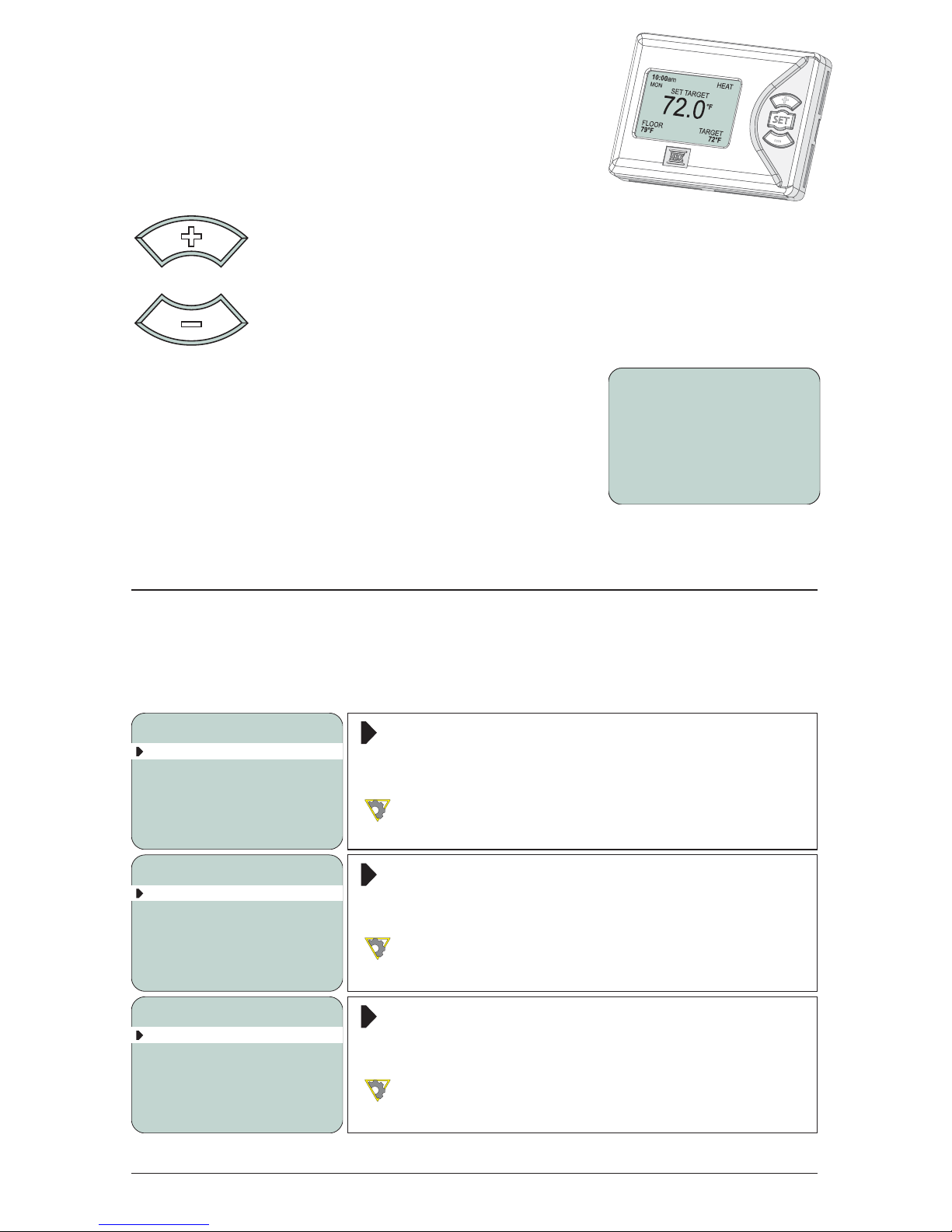
The + button is used to scroll up in menu screens and increase a
The - button is used to scroll down in menu screens and decrease
Pressing the +or -button on their own for 2 seconds
while viewing the main “Status Screen” will allow you
to quickly adjust your target temperature. Once you
have reached the desired target temperature by
using the +and -
return the thermostat to the initial “Status Screen”
mode.
SETTING THE THERMOSTAT
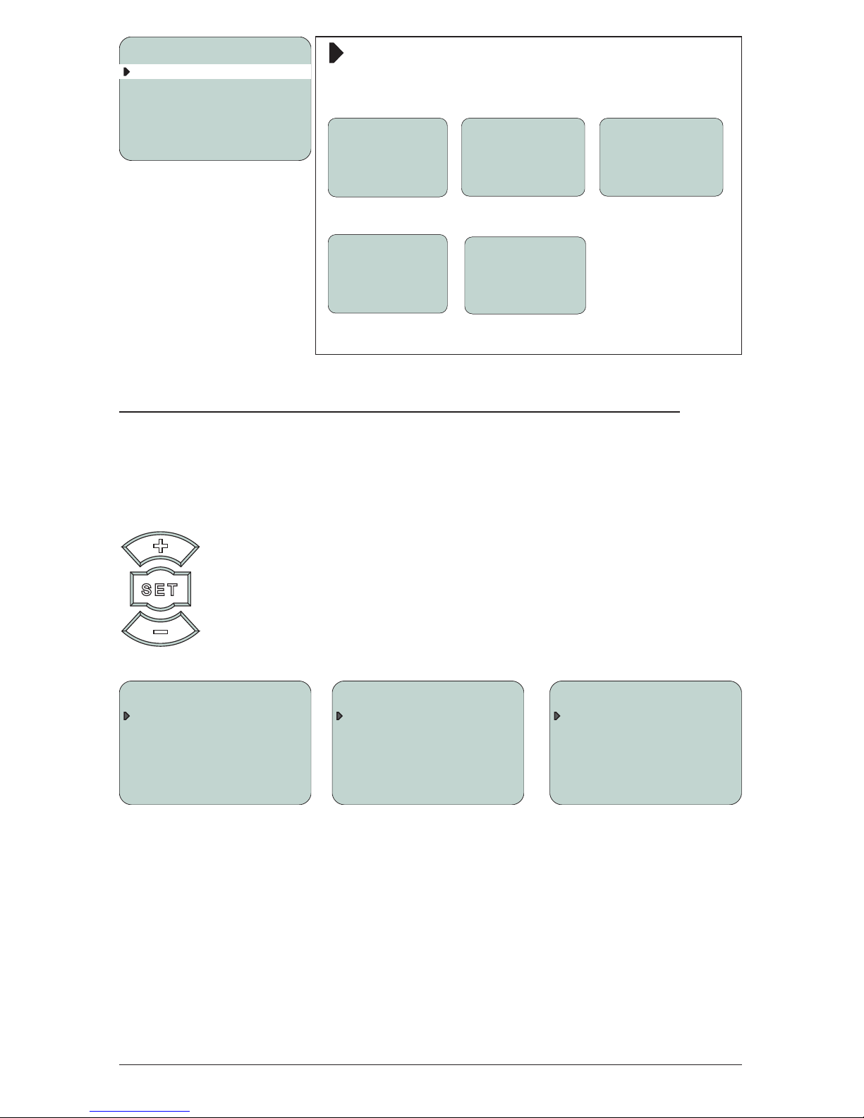
Special Functions
Enter the “Special Functions” screen by holding down the +and -buttons
simultaneously for 5 seconds (from the “Status Screen”). To select the desired
option, use the +and -buttons to toggle and the set button to select.
1) Type - Select between Heating, Cooling, and Setpoint modes.
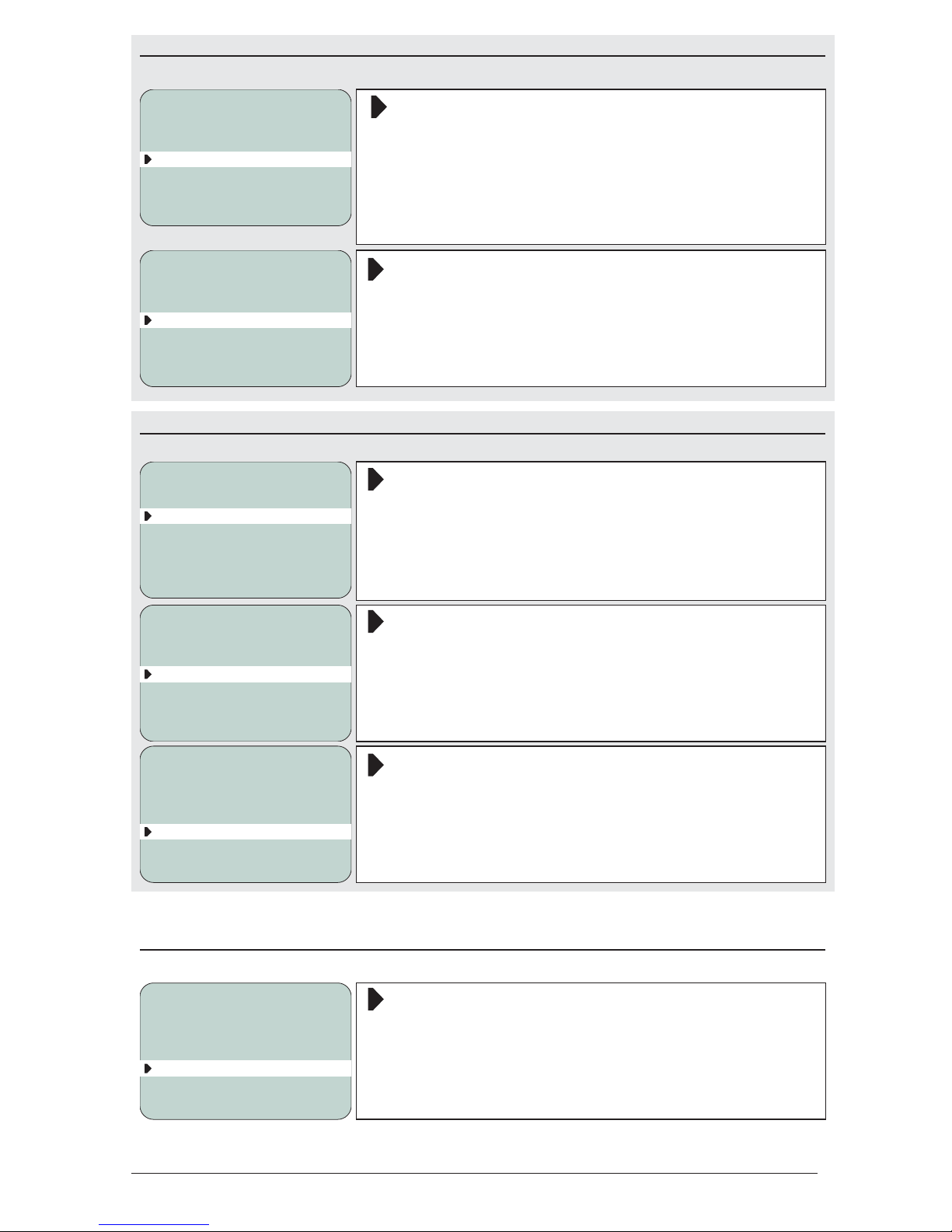
Heat Function
Select the “Heat Function” for applications using a
single heating source.
See diagram 1 for wiring examples.
1) TYPE HEAT
2) VIEW ALL YES
SPECIAL FUNCTIONS
Cool Function
Select the “Cool Function” for applications using a
single cooling source.
See diagram 2 for wiring example.
1) TYPE COOL
2) VIEW ALL YES
SPECIAL FUNCTIONS
Setpoint Function
Select the “Setpoint Function” for applications using
pumps, fancoils and other equipment.
See diagram 3 for wiring example.
1) TYPE SETPNT
2) VIEW ALL YES
SPECIAL FUNCTIONS
72.0°F
10:00am
MON SET TARGET
FLOOR
79°F TARGET
72°F
HEAT

View All/ Hide All
on the Status Screen.
1) TYPE COOL
2) VIEW ALL YES
SPECIAL FUNCTIONS
Adjustments
THE ADJUSTMENT SCREEN
Holding down the set button for 2 seconds while viewing the “Status Screen”
will take you into the “Adjustment Screen” for the respective thermostat modes
(Heating, Cooling or Setpoint).
Once you are in the desired options screen, use the +and -button
to scroll up and down. Press down the set button to choose the
option (the arrow to the left of your chosen option will turn black
+and -buttons
to adjust the value. Press the SET button to scroll between options
again.
72.0°F
ROOM
FLOOR
79°F TARGET
72°F
HEAT
72.0°F
10:00am
ROOM
No external sensor
installed
72.0°F
10:00am
ROOM
FLOOR
79°F TARGET
72°F
HEAT
72.0°F
ROOM
____
10:00am
Setpoint
TARGET
198°F
COOLING ADJUSTMENT
1) ROOM 70°F
2) SENSOR 1 FLOOR
3) C OR F °F
4) BACKLIGHT OFF
5) TIME 1:05am
HEATING ADJUSTMENT
1) ROOM TEMP 70°F
2) MODE ROOM
3) SENSOR 1 FLOOR
4) C OR F °F
5) BACKLIGHT OFF
6) TIME 1:05am
SETPOINT ADJUSTMENT
1) SETPOINT 130°F
2) MODE HEAT
3) DIFF 20°F
4) LAG TIME 0S
5) C OR F °F
6) TIME 1:05am

© 2014 HBX Controls4
HEATING ADJUSTMENT SETTINGS
The Heating Adjustment screen is applicable to the Heating option , selected
in the special functions screen. Enter the Heating Adjustment screen by
holding the SET button after selecting “Heat”.
Room Temperature
Set this value to the desired room target.
Range from 32°F to 200°F
HEATING ADJUSTMENT
1) ROOM TEMP 70°F
2) MODE ROOM
3) SENSOR 1 FLOOR
4) C OR F °F
5) BACKLIGHT OFF
6) TIME 1:05am
MODE OPTIONS
This option allows you to select between Room, Floor or Dual
Room Mode
HEATING ADJUSTMENT
1) ROOM TEMP 70°F
2) MODE ROOM
3) SENSOR 1 NONE
4) C OR F °F
5) BACKLIGHT OFF
6) TIME 1:05am
Room Mode
Sensor temperature providing feedback for the
thermostat.
Sensor 1 (Only Applies in Room Mode)
Enable the feedback sensor as None, Room, Floor,
Outdoor or Room Average in Floor mode
None - No external sensor is connected to the
Thermostat.
Room - The external sensor is used to control the
room temperature.
Floor – The external sensor is used to display the
Outdoor – The external sensor is used to display the
outdoor temperature.
Room Average - This setting averages the external
sensor and internal sensor to control the room
temperature.
HEATING ADJUSTMENT
1) ROOM TEMP 70°F
2) MODE ROOM
3) SENSOR 1 NONE
4) C OR F °F
5) BACKLIGHT OFF
6) TIME 1:05am

5
Floor Mode
Floor Mode
Sensor temperature providing feedback from the
HEATING ADJUSTMENT
1) ROOM TEMP 70°F
2) MODE FLOOR
3) DIFF 20°F
4) C OR F °F
5) BACKLIGHT OFF
6) TIME 1:05am
Differential (Only Applies in Floor Mode)
instigate a heat demand.
HEATING ADJUSTMENT
1) ROOM TEMP 70°F
2) MODE FLOOR
3) DIFF 20°F
4) C OR F °F
5) BACKLIGHT OFF
6) TIME 1:05am
Dual Mode
Dual Mode
Sensor temperature providing feedback for both
HEATING ADJUSTMENT
1) ROOM TEMP 70°F
2) MODE DUAL
3) FLOOR MAX 85°F
4) FLOOR MIN 65°F
5) C OR F °F
6) TIME 1:05am
Floor Maximum (Only Applies in Dual Mode)
The thermostat will not allow the temperature in the
HEATING ADJUSTMENT
1) ROOM TEMP 70°F
2) MODE DUAL
3) FLOOR MAX 85°F
4) FLOOR MIN 65°F
5) C OR F °F
6) TIME 1:05am
Floor Minimum (Only Applies in Dual Mode)
The thermostat will not allow the temperature in the
HEATING ADJUSTMENT
1) ROOM TEMP 70°F
2) MODE DUAL
3) FLOOR MAX 85°F
4) FLOOR MIN 65°F
5) C OR F °F
6) TIME 1:05am
Additional Settings
Celsius or Fahrenheit
Change the values in the thermostat to display
either the Celsius or Fahrenheit scale.
HEATING ADJUSTMENT
1) ROOM TEMP 70°F
2) MODE ROOM
3) SENSOR 1 NONE
4) C OR F °F
5) BACKLIGHT OFF
6) TIME 1:05am

© 2014 HBX Controls
Backlight
Toggling this option will turn the backlight feature
the backlight to power off.
HEATING ADJUSTMENT
1) ROOM TEMP 70°F
2) MODE ROOM
3) SENSOR 1 NONE
4) C OR F °F
5) BACKLIGHT OFF
6) TIME 1:05am
Time
HEATING ADJUSTMENT
1) ROOM TEMP 70°F
2) MODE ROOM
3) SENSOR 1 NONE
4) C OR F °F
5) BACKLIGHT OFF
6) TIME 1:05am
COOLING ADJUSTMENT SETTINGS
The Cooling Adjustment screen is applicable to the Cooling option , selected
in the special functions screen. Enter the Cooling Adjustment screen by
holding the SET button after selecting “Cool”.
Room Temperature
Set this value to the desired room target.
Range from 32°F to 200°F
COOLING ADJUSTMENT
1) ROOM 70°F
2) SENSOR 1 FLOOR
3) C OR F °F
4) BACKLIGHT OFF
5) TIME 1:05am
Sensor 1
Enable the feedback sensor as None, Room, Floor,
Outdoor or Room Average in Floor mode
None - No external sensor is connected to the
Thermostat.
Room - The external sensor is used to control the
room temperature.
Floor – The external sensor is used to display the
Outdoor – The external sensor is used to display the
outdoor temperature.
Room Average - This setting averages the external
sensor and internal sensor to control the room
temperature.
COOLING ADJUSTMENT
1) ROOM 70°F
2) SENSOR 1 FLOOR
3) C OR F °F
4) BACKLIGHT OFF
5) TIME 1:05am

7
Celsius or Fahrenheit
Change the values in the thermostat to display
either the Celsius or Fahrenheit scale.
COOLING ADJUSTMENT
1) ROOM 70°F
2) SENSOR 1 FLOOR
3) C OR F °F
4) BACKLIGHT OFF
5) TIME 1:05am
Backlight
Toggling this option will turn the backlight feature
the backlight to power off.
COOLING ADJUSTMENT
1) ROOM 70°F
2) SENSOR 1 FLOOR
3) C OR F °F
4) BACKLIGHT OFF
5) TIME 1:05am
Time
COOLING ADJUSTMENT
1) ROOM 70°F
2) SENSOR 1 FLOOR
3) C OR F °F
4) BACKLIGHT OFF
5) TIME 1:05am
SETPOINT ADJUSTMENT SETTINGS
The Setpoint Adjustment screen is applicable to the Setpoint option , selected
in the special functions screen. Enter the Setpoint Adjustment screen by
holding the SET button after selecting “Setpnt”.
Setpoint
Set this value to the desired setpoint target.
SETPOINT ADJUSTMENT
1) SETPOINT 130°F
2) MODE HEAT
3) DIFF 20°F
4) LAG TIME 0S
5) C OR F °F
6) TIME 1:05am
Mode
Select between Heat mode or Cool mode.
SETPOINT ADJUSTMENT
1) SETPOINT 130°F
2) MODE HEAT
3) DIFF 20°F
4) LAG TIME 0S
5) C OR F °F
6) TIME 1:05am
Differential
A differential of 10° is 5° above the setpoint and 5°
below the setpoint.
SETPOINT ADJUSTMENT
1) SETPOINT 130°F
2) MODE HEAT
3) DIFF 20°F
4) LAG TIME 0S
5) C OR F °F
6) TIME 1:05am

© 2014 HBX Controls8
Lag Time
Set the desired lag time interval.
SETPOINT ADJUSTMENT
1) SETPOINT 130°F
2) MODE HEAT
3) DIFF 20°F
4) LAG TIME 0S
5) C OR F °F
6) TIME 1:05am
Celsius or Fahrenheit
Set the display value as either Celsius or Fahrenheit.
SETPOINT ADJUSTMENT
1) SETPOINT 130°F
2) MODE HEAT
3) DIFF 20°F
4) LAG TIME 0S
5) C OR F °F
6) TIME 1:05am
Time
SETPOINT ADJUSTMENT
1) SETPOINT 130°F
2) MODE HEAT
3) DIFF 20°F
4) LAG TIME 0S
5) C OR F °F
6) TIME 1:05am
MOUNTING AND WIRING INSTRUCTIONS
Mounting Guide
Once you have wired the terminal block, the THM-0100 can be mounted on
the desired interior wall. The unit should be placed in an area clear of drafts
reading of the thermostat.

9
1
2
3456
1 - 2: Dry Contact Output
3 - 4: External Thermistor
5 - 6: 10-24V AC or DC
WIRING DIAGRAMS
Wiring Guide
1. HEATING
7+0
HBX
2
24V AC
65
2
TH
2
TH
43
3
7KHUPRVWDW
RL
1
RL
21
1
2 A DO NOT
CONNECT
POWER HERE
v
WRC
Transformer
24VAC
7+0
HBX
2
24V AC
65
2
TH
2
TH
43
3
7KHUPRVWDW
RL
1
RL
21
1
2 A DO NOT
CONNECT
POWER HERE
v
RC
Transformer
24VAC
Dry Contact
Output

© 2014 HBX Controls10
3. SETPOINT
RC
Transformer
24VAC
Dry Contact
Output
Sensor
7+0
HBX
2
24V AC
65
2
TH
2
TH
43
3
7KHUPRVWDW
RL
1
RL
21
1
2 A
DO NOT
CONNECT
POWER HERE
v
2. COOLING
7+0
HBX
2
24V AC
65
2
TH
2
TH
43
3
7KHUPRVWDW
RL
1
RL
21
1
2 A DO NOT
CONNECT
POWER HERE
v
YRC
Transformer
24VAC
7+0
HBX
2
24V AC
65
2
TH
2
TH
43
3
7KHUPRVWDW
RL
1
RL
21
1
2 A DO NOT
CONNECT
POWER HERE
v
RC
Transformer
24VAC
Dry Contact
Output

11
NOTES:

© 2014 HBX Controls12
NOTES:

LIMITED WARRANTY
HBX Controls warrants each of its products to be free from defects in workmanship and materials
under normal use and service for a period of 24 months from date of manufacture or 12 months
after date of manufacture.
If the product proves to be defective within the applicable warranty period, HBX on its sole
discretion will repair or replace said product. Replacement product may be new or refurbished of
not be of identical design or model. Any repair or replacement product pursuant to this warranty
shall be warranted for not less than 90 days from date of such repair, irrespective of any earlier
expiration of original warranty period. When HBX provides replacement, the defective product
becomes the property of HBX Controls.
Warranty Service, within the applicable warranty period, may be obtained by contacting your
provided to expedite the issuance of a Factory RMA.
After an RMA number has been issued, the defective product must be packaged securely in
the original or other suitable shipping package to ensure that it will not be damaged in transit.
The RMA number must be visible on the outside of the package and a copy included inside the
shipped back to purchaser at purchaser’s expense. HBX reserves the right, if deemed necessary,
to charge a reasonable levy for costs incurred, additional to mailing or shipping costs.
LIMITATION OF WARRANTIES
If the HBX product does not operate as warranted above the purchasers sole remedy shall be,
at HBX’s option, repair or replacement. The foregoing warranties and remedies are exclusive
and in lieu of all other warranties, expressed or implied, either in fact or by operation of law,
in connection with the sale, installation maintenance or use of HBX Controls products.
HBX shall not be liable under this warranty; if its testing and examination discloses that the alleged
defect in the product does not exist or was caused by the purchasers or third persons misuse,
LIMITATION OF LIABILITY
or other incidental, consequential or indirect damages arising out of the installation, maintenance,
commissioning, performance, failure or interruption of an HBX product, however caused and on
any theory of liability. This limitation will apply even if HBX has been advised of the possibility of
such damage.
LOCAL LAW
Canada and from Country to Country elsewhere in the world.
and limitations of this statement may not apply to the purchaser. For example, some states in
Provinces), may: Preclude the disclaimers and limitations in this statement from limiting the statutory
Otherwise restrict the ability of a manufacturer to enforce such disclaimers or limitations; or grant
the purchaser additional warranty rights which the manufacturer cannot disclaim, or not allow
limitations on the duration of implied warranties.

Other manuals for THM-0100
2
Table of contents
Other HBX Thermostat manuals
Popular Thermostat manuals by other brands

Siemens
Siemens 5TG5930-1WH operating instructions

Daikin
Daikin D2270C Owner's Manual & Installation Instructions

Lux Products
Lux Products PSD010BFb Installation and operating instructions

White Rodgers
White Rodgers 1F56 Series installation instructions

Vive
Vive TP-S-855CR installation manual

Robertshaw
Robertshaw 900 series Information sheet