Healthmark MM513-100 User manual

Instructions for Use: Insulation Tester and Bi-Polar Fixture
Brand Name of Product
Insulation Tester and Bi-Polar Fixture
Generic Name of Product
Insulation Tester and Bi-Polar Fixture
Product Code Number(s)
MM513-100, MM513-600, MM513-120EU, MMBPT-190, MMBRU-007, MMLSE-
0029, MMTRI-0022A, MMSBT-170
Intended Use
Compact, handheld, battery operated unit that tests the integrity (e.g., pinholes, cracks, or
defects) of the insulation of electrosurgical instruments to prevent tissue burns of
laparoscopic and bipolar electrosurgical instruments.
Range of Applications for Product
Used to test the integrity of the insulation of electrosurgical instruments (ESI) and
cable/cords for laparoscopic, endoscopic, intraoperative instruments, monopolar and
bipolar surgical items.
Key Specifications of Product
●Insulation Tester- MM513-100
●Bi-Polar Fixture and Black Connector—MMBPT-190
●Training CD
●Quick Operation Guide (manual)
●On and off switch
●Lightweight portable unit
●Measurements:
○Weight: 0.672 pounds (305 g)
○Voltage: 0- to 5 kV fully adjustable
○Resolution: 10 V
●Current output: < 0.1 mA (0.0001 A) at probe.
●Short circuit: test current < 0.1 mA max.
●Power supply: 1800 mAh Li-Polymer Battery.
●Probes:
oMedical style brass wire eight (8) mm wide brush, trim length of two
(2) mm. (NOTE: Probe size/shape may vary depending on user
requirement)
oReusable/interchangeable brush, ring, or Tri-Hole electrode
oTest stand—Saddle Block.
●System case
●Ground wire (green wire):
○with alligator clip—six (6) feet
○with clamp on one end—two (2) m.
●Power supply option: 5 V external rechargeable battery with adaptor.
●Lithium Polymer battery.
●Dimensions: 8.5- x 3.1- x 1.5 inches (215- x 78- x 38 mm)
●Ten (10)-hour operational time (up to 1000 instruments), two (2)- to 4-hour
recharging cycle.
●Simple operation, easy to read LED indicators.
●Maintains applied test voltage with constant current source.
●Full test current at low voltages.
●Limited output current for operational safety.
●Voltage up and down buttons
●LED displays alarm (audible and visual) and battery charge
●C-Style adapter wall charger
Brush Range Voltage
Brush
Electrode
MMBRU-007
LS Ring
Electrode
MMLSE-0029
Tri-Hole
Electrode
MMTRI-
0022A
Bi-Polar
Fixture
MMBPT-
190
Wire Tester
MMWIT-
200A
3.0 ± 0.3 kV
2.8 ± 0.3 kV
4.2 ± 0.3 kV
2.8 ± 0.3 kV
4.2 ± 0.3 kV
Kit Contents
Insulation Kit Includes:
Document
Version
4

Insulation Kit Insulation Tester MM513-100
(Bi-Polar Fixture Black Connector)-MMBPT-190
Ring and Brush Electrodes-MMLSE-0029 Ground Wire with Alligator Clip
Tri-Hole Electrode- MMTRI-0022A Saddle Block- MMSBT-170
Document
Version
4

Brush- MMBRU-007 Case
Quick Start Manual
Shipping & Storage
Shipping Conditions &
Requirements
N/A
Storage Conditions
N/A
Packaging Conditions
N/A
Shelf Life
N/A
Instructions for Using Product
Description of Use(s)
For testing insulation integrity of electrosurgical instruments.
Preparation for Use
1. Turn the unit on.
2. Check battery LED indicator colors:
Red=Battery Flat Blue=Charging Green=Battery Full
Document
Version
4

a. If the unit’s battery level is red, recharge using the charger adapter supplied
with the insulation tester kit. (NOTE: Use of any other charger may cause
damage to the insulation tester unit and void warranty.)
b. Only use this unit if it is at Green=Battery Full.
3. Connect the HV probe and ground leads to the unit.
4. Connect the ground clamp to the metallic substrate of the item to be tested.
Substrate should be grounded.
5. Attach the selected probe (ring, brush, Tri-Hole, or Saddle block) to the HV
Wire or base unit port (red).
6. Power on unit and select voltage.
7. Place the probe near the metal substrate.
8. A spark should occur (if not recheck all leads).
9. The unit should now be ready for use.
10. Test the coated surface by lightly moving the probe (brush, ring, and Tri-Hole
electrode) slowly (approximately three [3] feet every four [4] seconds) across
the surface of the unit under test. (See Operational Guide for Saddle block.)
Diagrams (drawings, pictures)
N/A
Steps for Use of Product
1. Remove the insulation tester unit and accessories from the carrying case.
2. Take the green ground wire and firmly insert it into the green port on the bottom
of the base unit. (Fig. 1).
Figure 1 Insulation Tester
3. Secure the Saddle block to a flat (preferably metal) surface by pushing down on
the top of the unit until the suction feet stick to the surface. (Fig. 2).
Figure 2
4. Attach the red port on the top of the insulation tester unit directly to the side pin
of the Saddle block. Make sure controls face up. (Fig. 3).
Figure 3 Figure 3
There are several ways to set the Saddle block up depending upon the
electrosurgical instrument (ESI) to be tested and/or the kit used.
1. Insert the chosen electrode securely into the proper slot on the Saddle block.
2. Take the clamp on the green ground wire and attach it to the conductive core of
the instrument under test.
3. Turn the base unit on and set the voltage to 2.8- ± 0.3 kV. (Fig. 4).
Document
Version
4

4. Use 4.2 ± 0.3 kV when using the Tri-Hole electrode.
Figure 4
5. Push the ESI under test through the LSE ring electrode slowly (approximately
three [3] feet every four [4] seconds).
6. The alarm will sound when the ESI (the bare tip of the instrument) is first
inserted into the electrode.
7. After the test is completed:
a. Turn the base unit off and remove the clamp end from the unit under
test.
b. Remove the electrode from the probe wire and remove the ground wire
and probe wire from the base unit.
c. Properly store the unit and accessories away.
8. Follow the hospital’s procedure policy with regards to the instrument under test.
(Note: The unit should always be switched off prior to removing or repositioning of the
ground lead, the HV red wire, or the saddle block. If the unit is on and you touch the
ground lead (clamp end) and the probe end of the base unit at the same time, you will
receive a very mild “tingle”. To remove the possibility of receiving the “tingle”, always
use surgical gloves when handling the leads. You can hold the saddle block from the top
or the sides—just don’t touch the connection points. [Fig. 5]).
Figure 5
For Round ESI, such as laparoscopic:
1. Insert the chosen electrode into the proper slot in the top of the Saddle Block.
Make sure the pin is securely placed in the hole. (Fig. 6).
Document
Version
4

Figure 6
2. If using the MM513 Kit, attach the HV Red wire to the pin on the side of the
Saddle Block or connect red port to the top of the unit directly to the side pin.
Make sure controls face up. (Fig. 7).
Figure 7
3. Take the clamp on the green ground wire and attach it to the conductive core of
the instrument under test. (Fig. 8).
Figure 8
4. Turn the base unit on and set the voltage to 2.8- +/- 0.3 kV. (Fig. 9).
Figure 9
5. Push the ESI under test through the LSE ring electrode slowly (approximately
three [3] feet every four [4] seconds).
6. Alarm will sound when the ESI (the bare tip of the instrument) is first inserted
into the electrode.
7. Alarm sounds/LED flashes if fault is found in the coating indicating a fault with
the instrument.
Using the Tri-Hole Electrode:
1. Same setup as shown above, except turn the voltage to 4.2- ± 0.3 kV.
Document
Version
4

2. Insert the round electrosurgical instrument ESI into hole-size closest to the
diameter of the ESI under test.
(Note: Hole sizes are slightly larger than 3-, 5-, and 10 mm from the bottom [pin
side up].)
Bi-Polar instruments (wear gloves):
1. Attach the red-port on the top of the insulation tester unit directly to the side pin
of the saddle block. (Make sure controls face up.)
2. Place the brush electrode into the Saddle Block’s slot on the right side away
from the pin. (Fig. 10).
Figure 10
3. Attach the green ground wire to the back end of the Bi-Polar forceps. Make sure
the clamp is connected to both pins.
4. Insert the end of one tine of the Bi-Polar forceps into the middle of the brush.
(Fig. 11).
Figure 11
5. Turn the base unit on and set the voltage to 2.8- ± 0.3 kV.
6. Slowly push the Bi-Polar forceps away from you. Go from the tip of the forceps
to the base.
7. Repeat using the second tine.
8. Turn the Bi-Polar forceps over and repeat the test of both tines.
9. Alarm sounds / LED flashes if fault is found in the coating indicating a fault
with the instrument.
Instructions for Using Bi-Polar Kit with the Insulation Tester Saddle
(Note: Wear gloves.)
1. Insert the Bi-Polar fixture in the saddle in the slot for the LSE ring electrode.
(Fig. 12).
Figure 12
2. Remove the clamp from the end of the green ground wire.
3. Insert either end of the black connector adaptor onto the end of the green wire.
(Fig. 13).
Document
Version
4

Figure 13
4. Insert the Bi-Polar fixture into the end of the black adapter.
5. Insert the Bi-Polar instrument into the top of the Bi-Polar fixture. (Fig. 14).
Figure 14
6. Turn on the insulation tester unit on and set voltage to 2.8- ± 0.3 kV.
7. Touch the bare tip of the Bi-Polar forceps to ensure that the alarm sounds, and
the system is operational.
8. Using the brush, slowly brush from top to bottom of each (Fig. 15):
a. On the outside of left side of tine
b. On the inside of left side of tine
c. On the inside of the right tine
d. On the outside of the right tine.
Figure 15
9. If the alarm sounds, the Bi-Polar has a fault. Follow standard facility procedures
for a defective electrosurgical instrument. (Note: place a repair tag on all
instruments that fail testing.)
Interpretation of Test Results
N/A
Contraindications of Test Results
N/A
Documentation
N/A
Special Warnings and Cautions
●This should be used in the Sterile Processing area ONLY during assembly and
inspection.
●The Lithium Polymer (LiPo) Battery can only be replaced at the McGan facility.
DO NOT attempt to replace the battery.
●(Only) use the charger that comes with the unit.
Document
Version
4

●DO NOT operate unit if you are not in good health. People with a cardiac
condition should not operate this unit.
●DO NOT operate this unit if you have a pacemaker. This unit should only be
used for checking porosity (or electrical breakdown) of dielectric or insulating
materials (e.g., Jacketing material, powder coatings).
●DO NOT use this unit around other machinery. An electrical shock may cause
the operator to fall and injure themselves.
●DO NOT operate this unit around people who not directly involved in the testing
procedure.
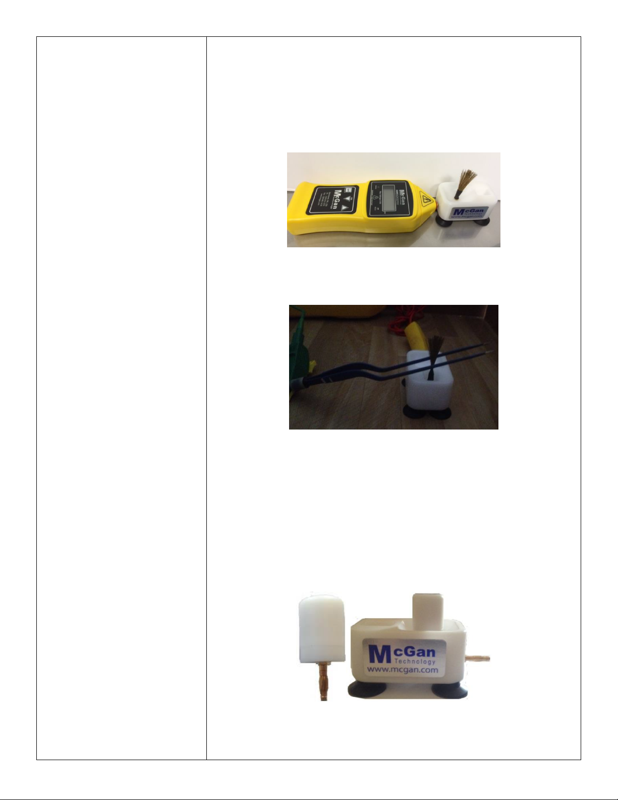
●DO NOT operate this unit other than McGan Technology Probes. McGan
Probes CAN ONLY be used with the appropriate McGan Insulation Tester(s).
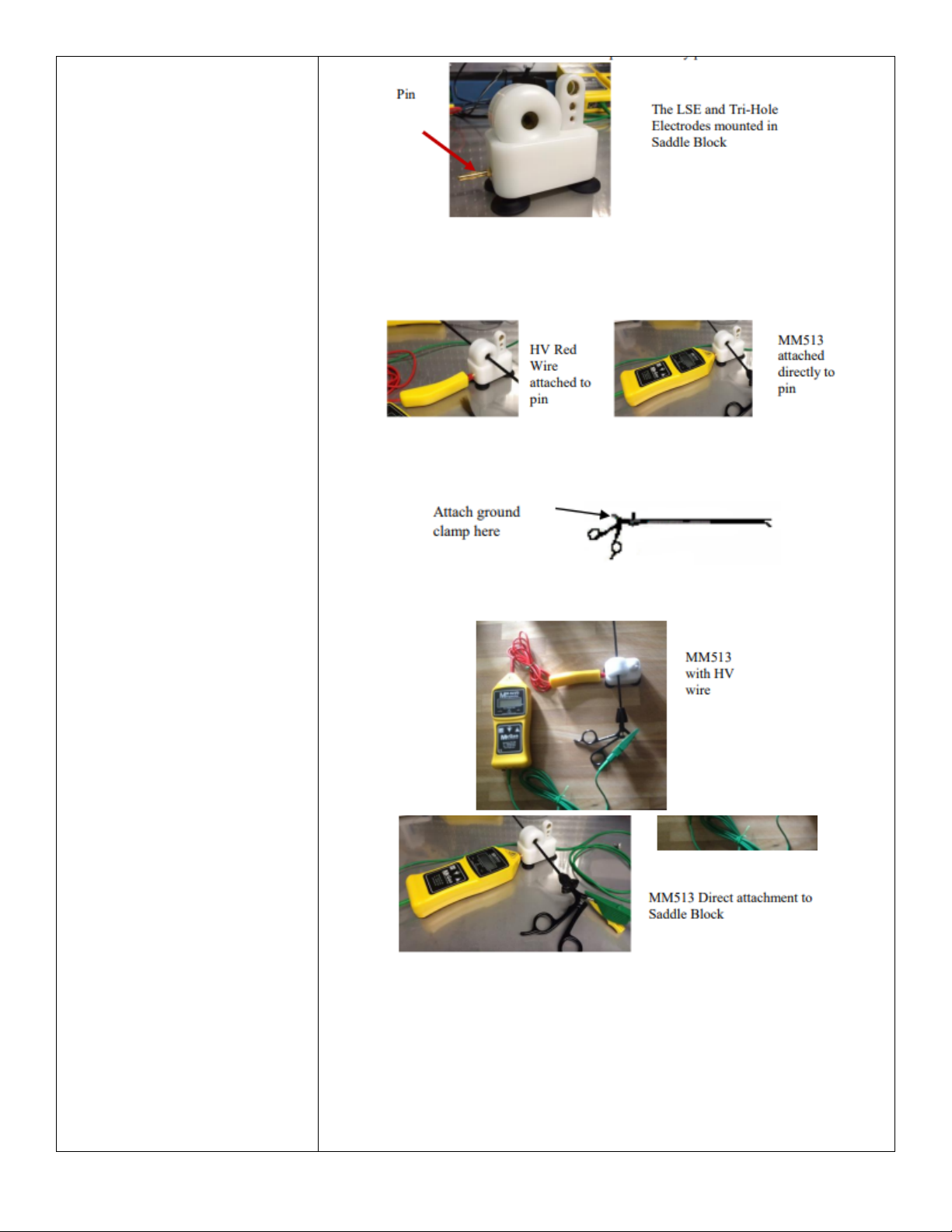
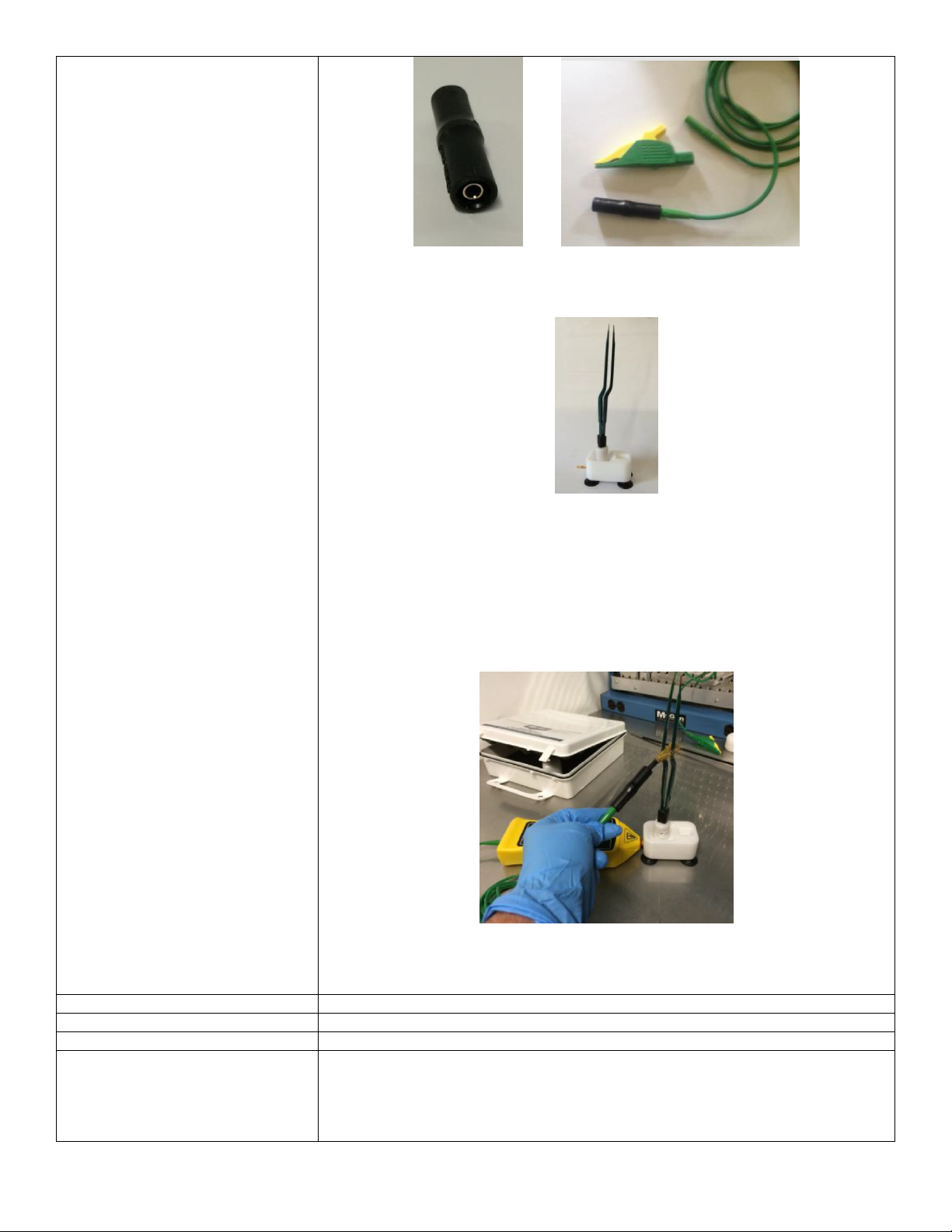
●DO NOT simultaneously handle the brush electrode and ground clamp, as it will
cause a mild “tingle”. Use surgical gloves as a precaution against “tingle”.
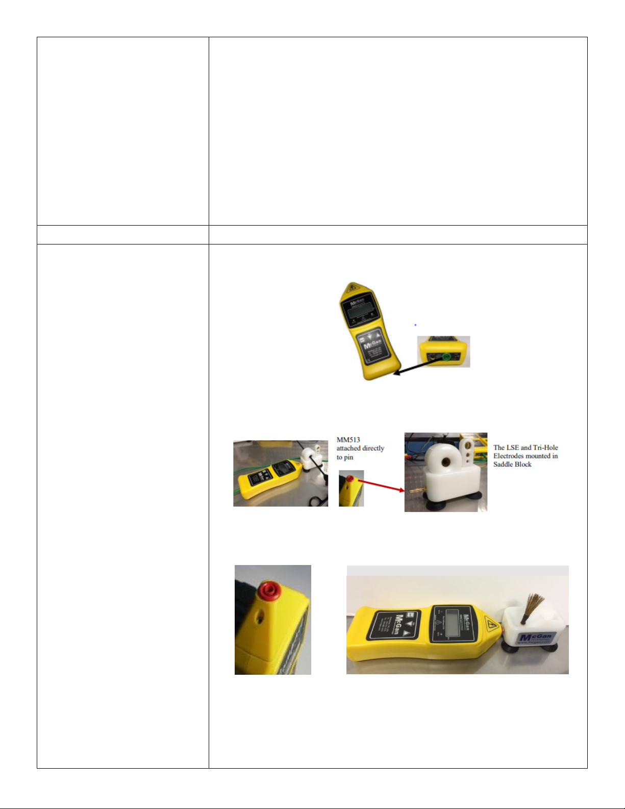
●You cannot operate the MM513 unit with the AC adaptor plugged into the
rechargeable battery port on the bottom of the base unit.
●ONLY USE Lithium Polymer (LiPo) battery and the associated AC power
adapter (PN/5VQACP-0015) provided with the M513 system.
●LED battery indicator light will illuminate when the unit is low on power.
oIf the power from the battery is too low the LED will not illuminate.
oIf the MM513 fails to operate due to battery failure, contact Customer
Service.
●Always keep the working end of any of the probe electrodes away from your
body
●Do not touch probe electrodes when the instrument is activated.
●After the instrument has been turned off, always ground the probe before
disassembling the unit to ensure that any residual charge has dissipated.
⚠
DANGER ⚠
●DO NOT use wet. After cleaning, thoroughly DRY all areas before using the
components, and inspect for any defects in the electrodes.
●DO NOT use the test equipment in any combustible or flammable
atmosphere (i.e., flammable anesthetics),as a test voltage can cause an arc or
spark to be generated and an explosion could result.
Troubleshooting
Symptom
Possible Cause
Solution
No display
Dead or low
charged battery
Fully charge
battery pack.
Alarm sounds
continuously during test
Surface might be
slightly conductive,
damp, or salty.
Probe moved too
fast
Wash, clean, and
dry the surface.
Move probe
approximately 3
feet (1-m) every 4
seconds.
No alarm on defect
Voltage is too low.
Increase voltage
sensitivity.
No spark at probe tip
Damaged leads
Poor connections
Dead or low
charged battery
Repair or replace
leads.
Clean and
reconnect.
Recharge the
battery.
No battery indicator
light and unit does not
function
Dead or low
charged battery.
Recharge the
battery.
Disposal
N/A
Document
Version
4

Reprocessing Instructions
Point of Use
Inspect for a) the alarm to sound, b) LED to light, and c) base unit is in clean and proper
working condition.
Preparation for Decontamination
N/A
Disassembly Instructions
N/A
Cleaning – Manual
Base Unit: Dab a lint-free cloth in alcohol and wipe down base unit.
Caution:
DO NOT get alcohol in/near the battery terminals and the green or red ports.
DO NOT saturate cloth.
Red HV Wire/Green Ground Wire:
●Inspect: Make sure there are no cuts, breaks, or abrasions on the cable
insulation. If they are replaced, make sure the connector post is not damaged.
●Use an alcohol swab and wipe both the red and green wires, including the mini-
handle (yellow) on the red HV wire.
Caution:
DO NOT get alcohol in/near red port on the top of the mini handle.
DO NOT use saturated cloth.
Reusable Brush Electrode
●Inspect: Make sure all bristles are not damaged.
●Can be wiped with alcohol.
Reusable Saddle block
●Inspect: Look for cracks in white housing. If they are replaced, make sure
electrode components fit securely in the proper slot.
●Can be wiped with alcohol.
Cleaning – Automated
N/A
Disinfection
N/A
Drying
N/A
Maintenance, Inspection, and
Testing
●Some organic materials may attack plastic parts and cause early degradation.
Avoid contact with such materials.
●It is recommended to calibrate the MM513 base unit (P/N MM513-110) at least
once per year to ensure it is operating at the appropriate voltage.
○Healthmark Industries can perform this service for a small fee. Please
contact Healthmark if you would like pricing or need to set up a test
system.
○Recalibrate when the instrument’s integrity is in question,or the
instrument has been damaged.
Reassembly Instructions
N/A
Packaging
N/A
Sterilization
N/A
Storage
N/A
Additional Information
Subject to the warranty conditions below, the MM513 is warranted by the manufacturer
to be free from defects arising from defect design or workmanship for a period of 12
months from the date of original purchase by the user.
Probes and leads are warranted for two (2) months. They are consumable items and
subject to wear and deterioration during use. The life of these parts can be extended by
keeping them in a clean and dry condition. The probes and leads must be stored in
suitable protective containers. During use, avoid “scrubbing” the probe along the surface
of the workpiece.
The warranty will be voided if the base unit (P/N MM513-110) has been disassembled
for any purpose. It is not necessary to access any component inside the unit. Return the
unit for repair.
Related Healthmark Products
N/A
Other Product Support Documents
ProSys™ Brochure, ProSys™ Price List
Document
Version
4

Reference Documents
N/A
Customer Service Contact
Healthmark Industries Company, Inc.
18600 Malyn Blvd.
Fraser, MI 48026
1-586-774-7600
hmark.com
Document
Version
4
Other manuals for MM513-100
1
This manual suits for next models
7
Table of contents
Other Healthmark Medical Equipment manuals
Popular Medical Equipment manuals by other brands

Dräger
Dräger G34525 Instructions for use

Kingkraft
Kingkraft Leit Trolley Instructions for use

Permobil
Permobil BodiLink Lateral Trunk Support Operation manual

Arjo
Arjo Lifeguard LG55 Instructions for use

Drive Medical
Drive Medical Celestia 18250 instruction manual

Juzo
Juzo JuzoPro Lumbal Xtec Strong Instructions for use