22010/4/7 Ver1.1+V1.2
Table of Content
Content ------------------------------------------------------------------------------------------------------
1. Components Check --------------------------------------------------------------------------------------
2. Overview Drawing ---------------------------------------------------------------------------------------
2-1 Computer Console --------------------------------------------------------------------------------
2-2 Software Update Slot -------------------------------------------------------------------------------
2-3 Wire Rod and Power Switch ------------------------------------------------------------------------
2-4 Running Belt and Side Incline Base ------------------------------------------------------------------
3. Caution
3-1 Caution --------------------------------------------------------------------------------------------------------
3-2 Electrical Power Requirement ---------------------------------------------------------------------------
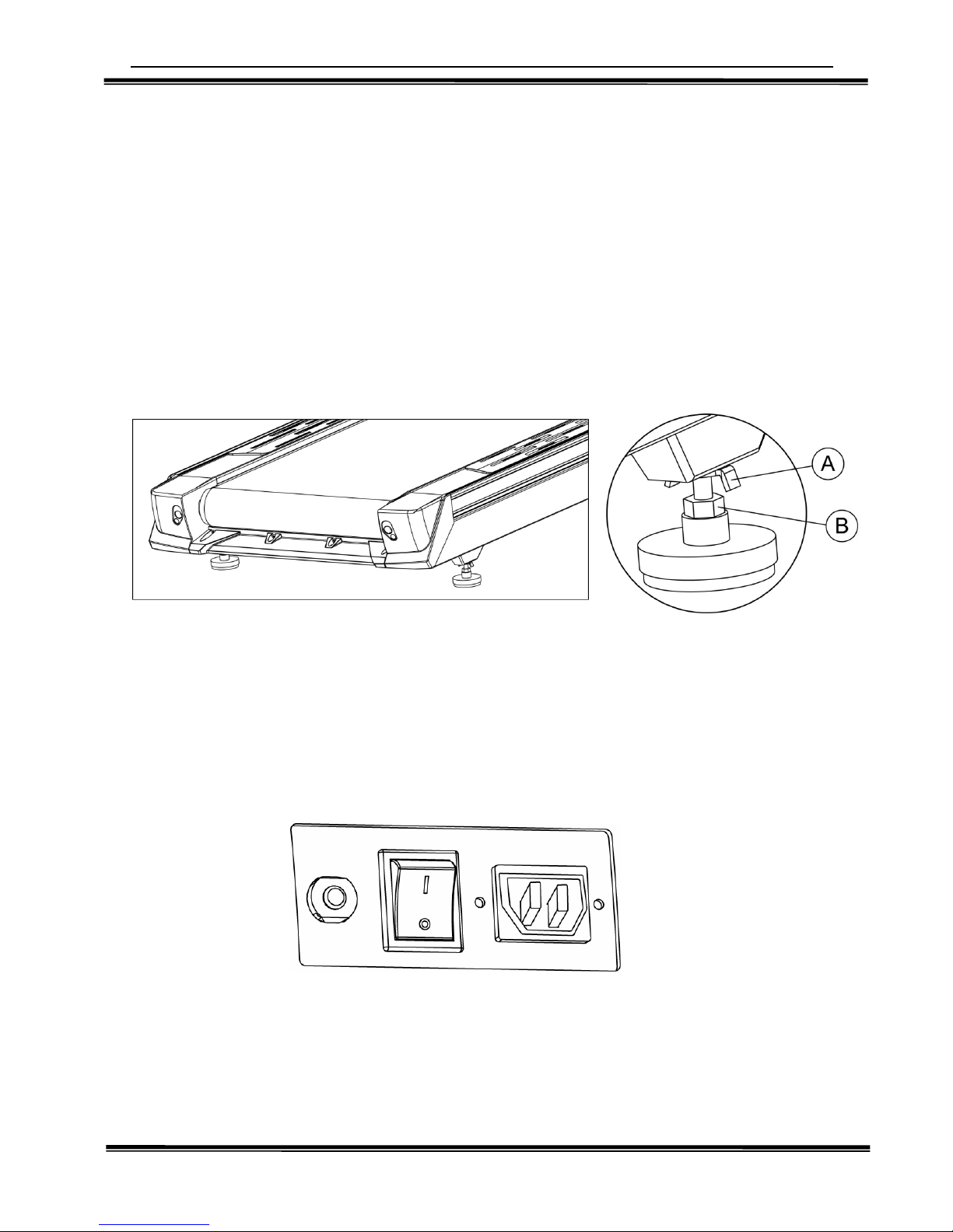
3-3 Leveling Adjustment --------------------------------------------------------------------------------
3-4 Power Switch ----------------------------------------------------------------------------------------
3-5 Centering The Belt ----------------------------------------------------------------------------------
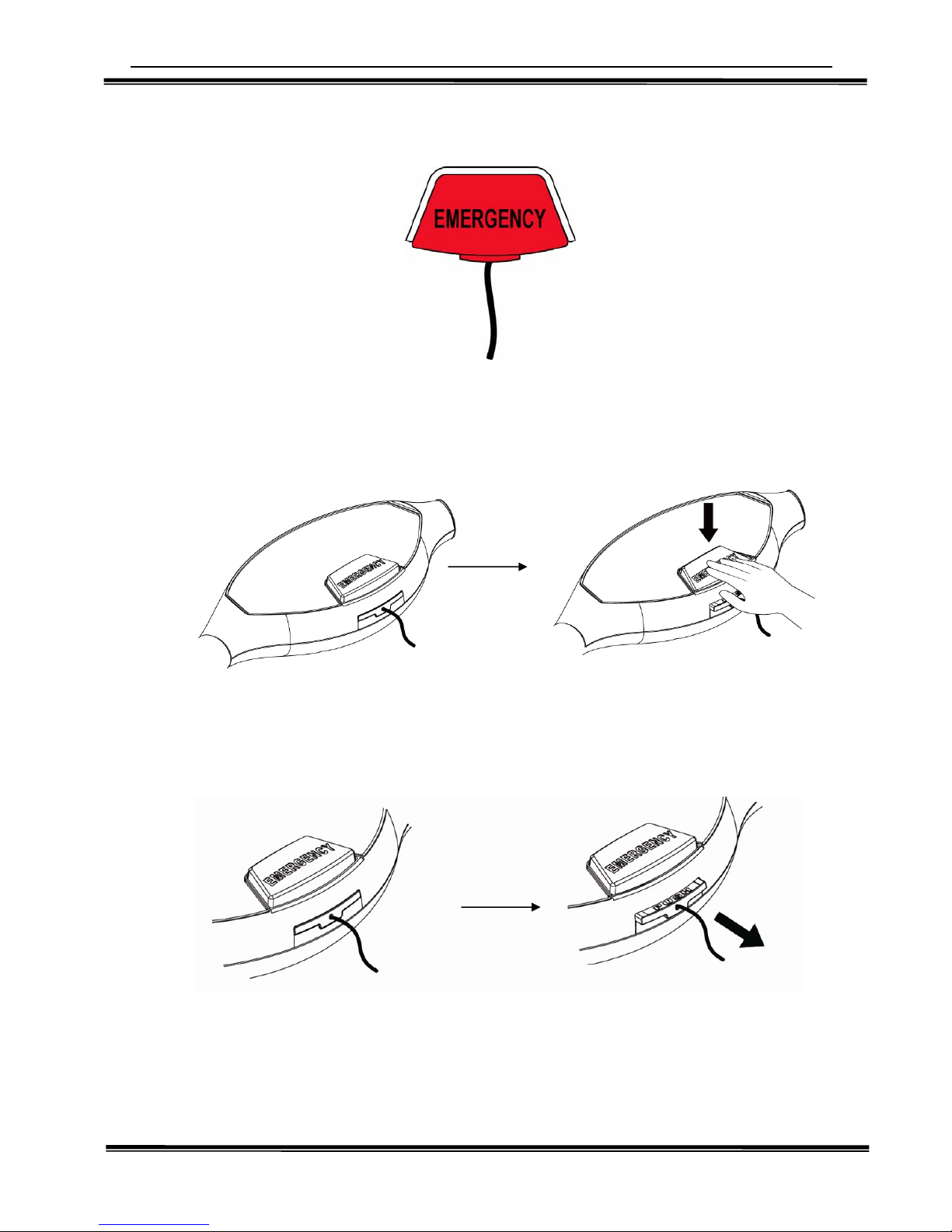
3-6 Emergency Stop System (Emergency) --------------------------------------------------------
4. Assembly Instruction
4-1 Pre-Assembly Check List ---------------------------------------------------------------------------
4-2 Assembly Steps -------------------------------------------------------------------------------------
5. Computer
5-1 Display Inter face Description ----------------------------------------------------------------------
5-2 Key Instructions--------------------------------------------------------------------------------------
5-3 Bottle Holder and Utilities Tray --------------------------------------------------------------------
5-4 Operation Instructions------------------------------------------------------------------------------
6. Workouts (Programs) ------------------------------------------------------------------------------------
Heart Rate Monitoring ----------------------------------------------------------------------------------
7. Video Operation Instructions--------------------------------------------------------------------------
8. Program Project Figure L1-L10 Speed/Incline Comparison Table----------------------------------
02
03
04
05
06
07
08
09
11
12
12
13
14
16
18
20
22
25
26
27
29
34
43
Page