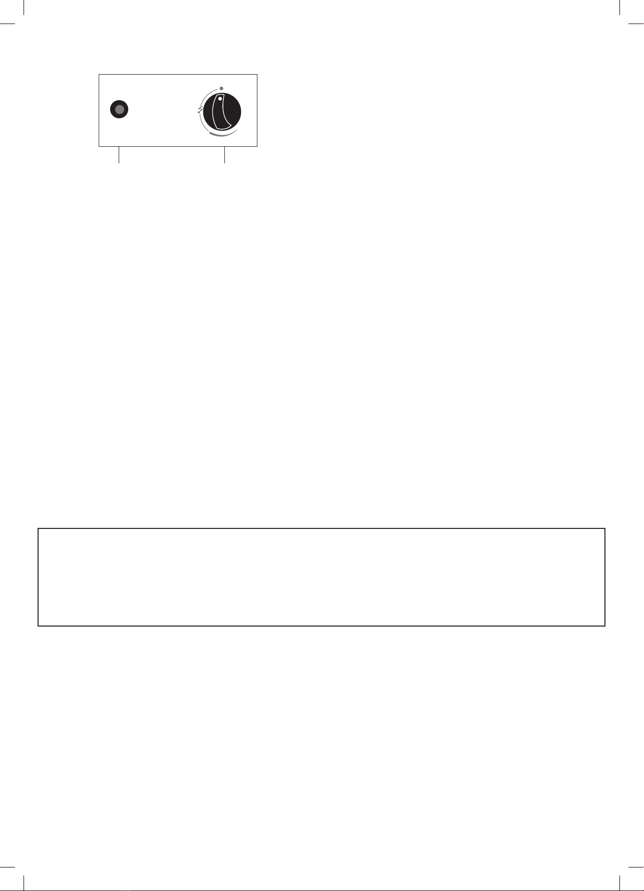
10.Secure the knob to the front door panel using the supplied M4 screw. Then attach the front door panel to the
heater via the pothooks of the front panel to the holes of the bottom plate. See Figure 10.
Installing a Gas Cylinder
IMPORTANT: This product does not come supplied with
a gas cylinder. This gas patio heater is only suitable for
a standard 7kg butane/propane gas cylinder which is
approximately 31cm in diameter and 45.5cm high.
WARNING:
Never use a rusted, dented or damaged gas cylinder.
To install the gas cylinder, simply secure the patio heater’s gas hose to the gas cylinder’s outliet via the gas hose’s
regulator. Screw it anti-clockwise. Then place it inside the patio heater’s cabinet and secure the buckle in place.
See Figure 11.
10
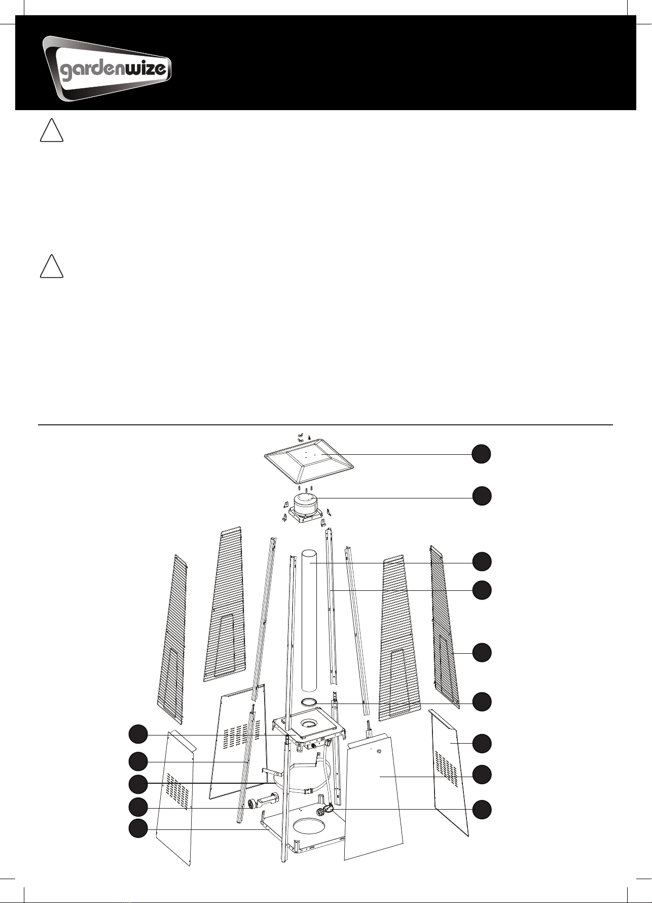
ASSEMBLY INSTRUCTIONS
9
10
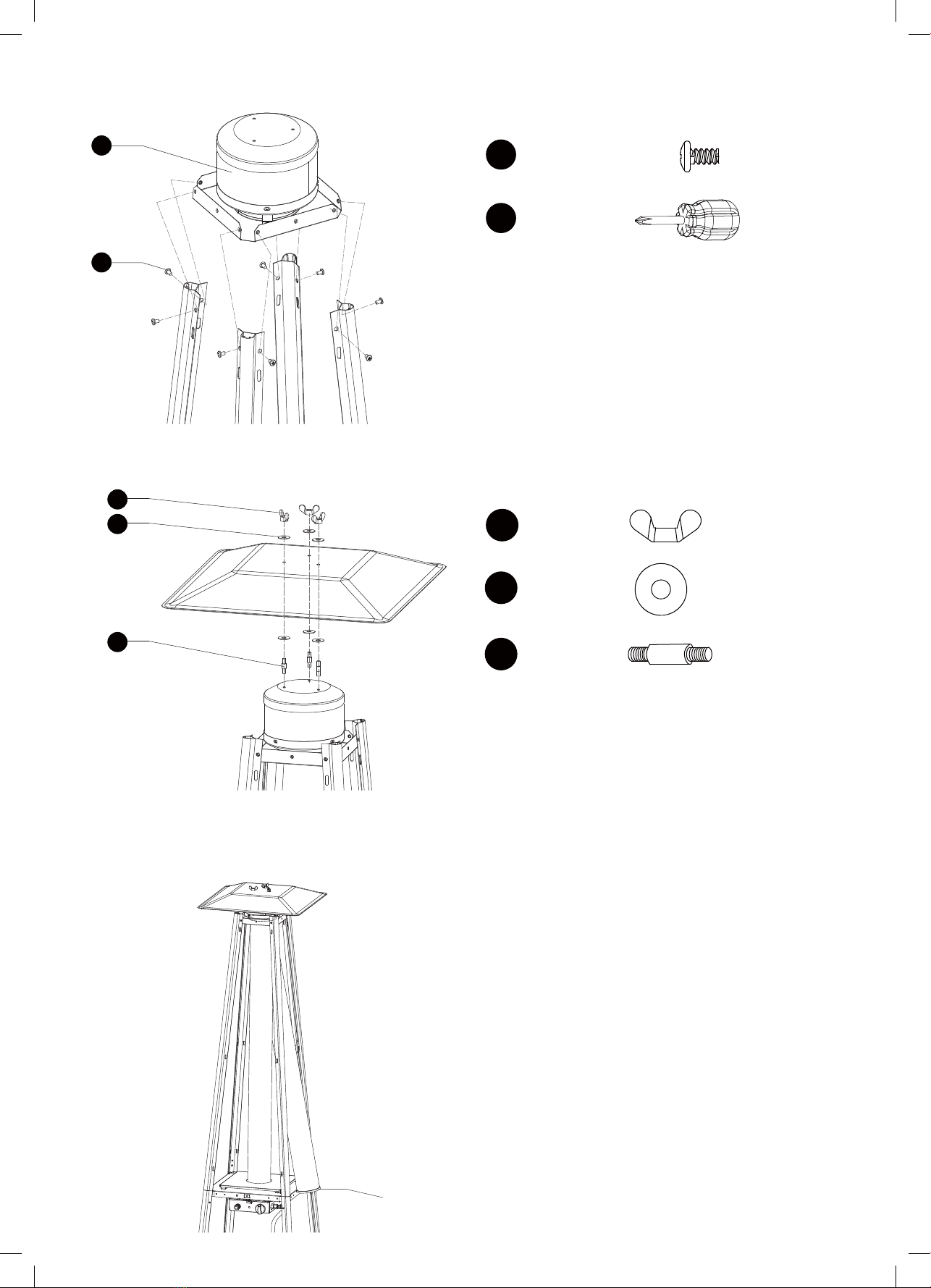
9. Attach the three side panels to the heater
using 18pcs screw 3/16”.
Note : Do not cover the front side where
the control knob is.
LL
MM
H
NN
DD
Hardware Used
DD
KK
x 18
Philips
screwdriver
3/16” Screw
x 1
10.Install the knob to M4x10 screw. Hang the
chain to the hole on the control box assy and
put the pothook of front panel to the holes of
bottom plate.
Hardware Used
x 1
LL Knob
MM
KK
x 1
x 1
Philips
screwdriver
Screw M4 X 10
x 1
NN Chain
10
ASSEMBLY INSTRUCTIONS
9
10
9. Attach the three side panels to the heater
using 18pcs screw 3/16”.
Note : Do not cover the front side where
the control knob is.
LL
MM
H
NN
DD
Hardware Used
DD
KK
x 18
Philips
screwdriver
3/16” Screw
x 1
10.Install the knob to M4x10 screw. Hang the
chain to the hole on the control box assy and
put the pothook of front panel to the holes of
bottom plate.
Hardware Used
x 1
LL Knob
MM
KK
x 1
x 1
Philips
screwdriver
Screw M4 X 10
x 1
NN Chain
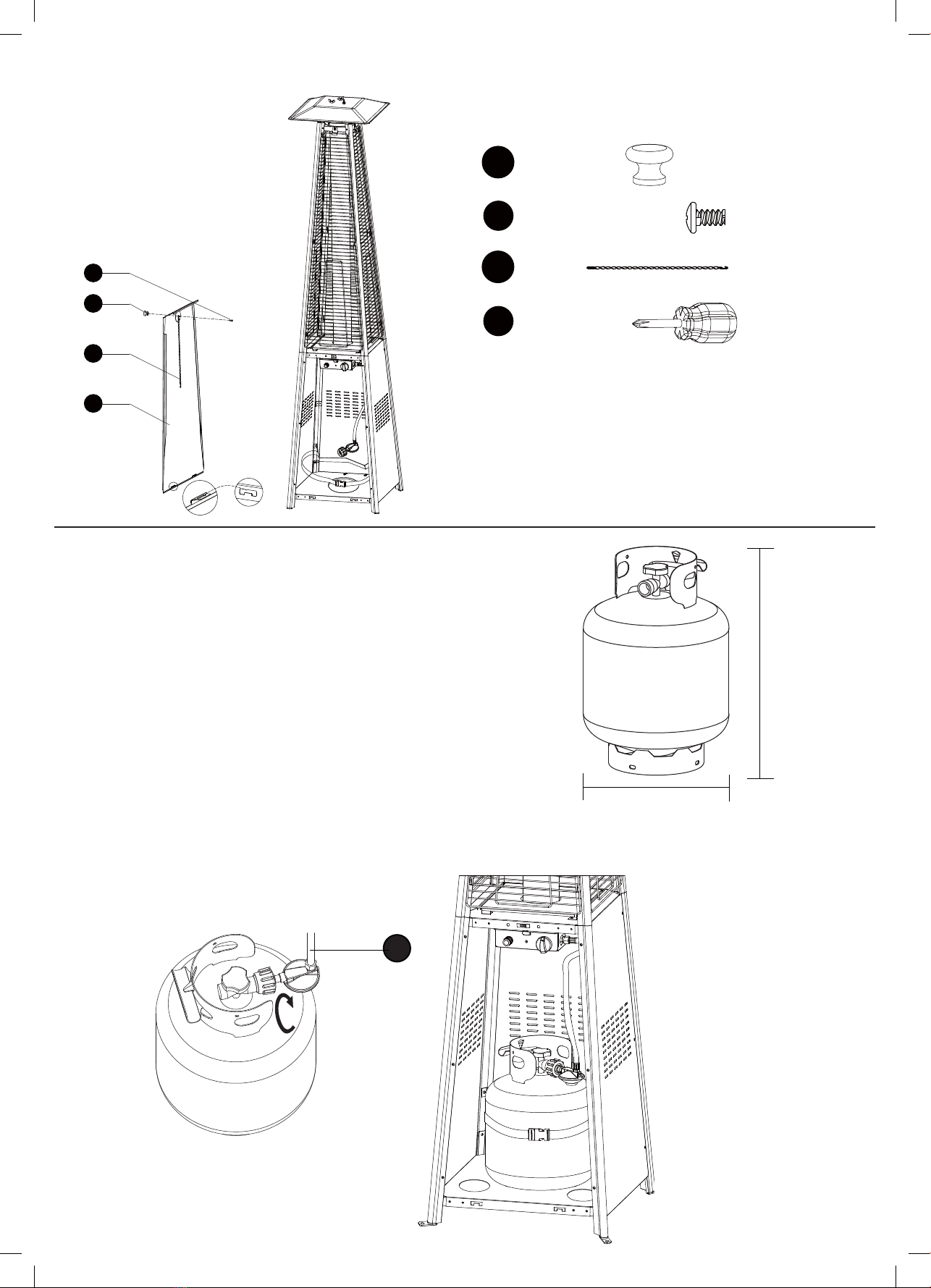
Figure 10
12
ASSEMBLY INSTRUCTIONS
Do not store a spare LP-gas cylinder under or near this appliance;
Never fill the cylinder beyond 80 percent full;
Place the dust cap on the cylinder valve outlet whenever the cylinder is not
in use. Only install the type of dust cap on the cylinder valve that is provided with
the cylinder valve. Other type of caps or plugs may result in leakage of propane.
A dented, rusted or damaged propane cylinder may be
hazardous and should be checked by your cylinder
supplier. Never use a propane cylinder with a damaged
valve connection.
The propane cylinder must be constructed and marked
in accordance with the specifications for LP gas
cylinders of the U.S. Department of Transportation
(DOT) or the standard for cylinders, spheres and
tubes for transportation of dangerous goods and
commission, CAN/CSA-B339.
The cylinder must have a listed overfilling prevention
device. The cylinder must have a connection device
compatible with the connection for the appliance. The
cylinder used must include a collar to protect the
cylinder valve. Never connect an unregulated propane
cylinder to the heater.
Standard 20 lb. tank
12.2 in. / 31cm
17.9 in. / 45.5cm
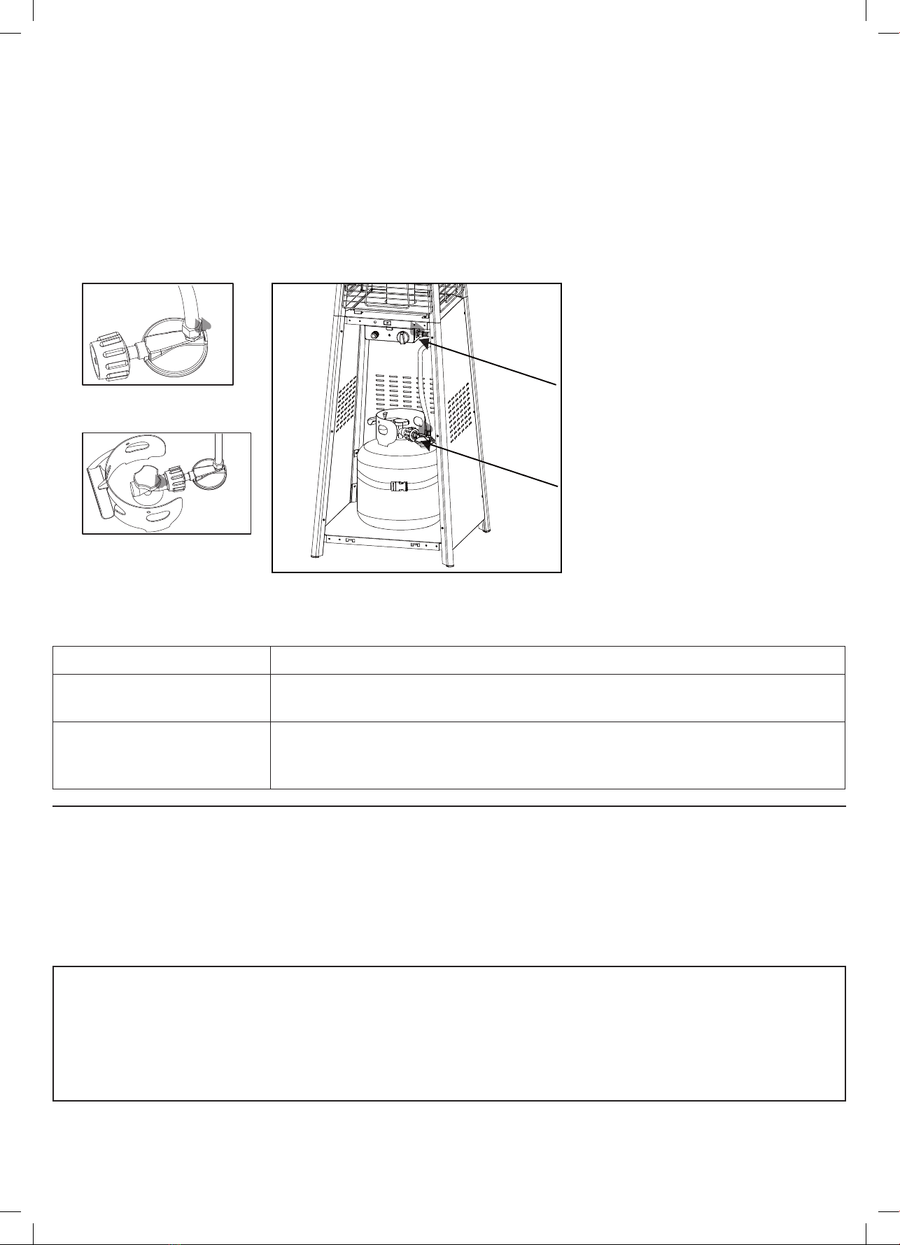
The knob on the LP tank must be closed. Make sure that
the knob is turned clockwise to a full stop. The
cylinder supply system must be arranged for vapor
withdrawal. Check that the control knob on the control
unit is turned off. Hold the regulator in one hand and
insert the nipple into the valve outlet. Be sure the nipple
is centered in the valve outlet. The coupling nut connects
to the large outside threads on the valve outlet.
Hand-tighten the coupling nut clockwise until it comes
to a full stop. Firmly tighten by hand only.
To Disconnect: Fully close the tank valve by turning
clockwise. Turn the coupling nut counterclockwise
until the regulator assembly detaches.
Figure 11
11
ASSEMBLY INSTRUCTIONS
11
11. Screw gas hose and regulator to propane cylinder
(not included). Do not cross-thread.
Use a standard 20 lb. propane cylinder only.
(approximately 12.2 in. / 31cm. in diameter and 17.9 in.
/ 45.5cm high).
Use this heater only with a propane vapor
withdrawal supply system. See chapter 5 of the standard
for storage and handling of liquefied petroleum gas,
ANS/NFPA 58. Your local library or fire department
should have this book. Storage of an appliance indoors
is permissible only if the cylinder is disconnected and
removed from the appliance. A cylinder must be stored
outdoors in a well-ventilated area out of the reach of
children. A disconnected cylinder must have dust caps
tightly installed and must not be stored in a building,
garage or any other enclosed area. The maximum inlet
gas supply pressure: 250 psi /1750 kPa. The minimum
inlet gas supply pressure: 5 psi /35kPa. Manifold
pressure with regulator provided: 11 inch W.C/ 2.74 kPa.
The minimum hourly of 17000 Btu /4.98 kW is required
input rating for an appliance for automatic operation at
ratings less than full input rating. The pressure regulator
and hose assembly supplied with the appliance must be
used. The installation must conform with local codes, or
in the absence of local codes,with national fuel gas code,
ANS Z223.1/NFPA54, natural gas and propane
Installation Code, CSA B149.1, or propane storage and
handling code, B149.2.
I
11
ASSEMBLY INSTRUCTIONS
11
11. Screw gas hose and regulator to propane cylinder
(not included). Do not cross-thread.
Use a standard 20 lb. propane cylinder only.
(approximately 12.2 in. / 31cm. in diameter and 17.9 in.
/ 45.5cm high).
Use this heater only with a propane vapor
withdrawal supply system. See chapter 5 of the standard
for storage and handling of liquefied petroleum gas,
ANS/NFPA 58. Your local library or fire department
should have this book. Storage of an appliance indoors
is permissible only if the cylinder is disconnected and
removed from the appliance. A cylinder must be stored
outdoors in a well-ventilated area out of the reach of
children. A disconnected cylinder must have dust caps
tightly installed and must not be stored in a building,
garage or any other enclosed area. The maximum inlet
gas supply pressure: 250 psi /1750 kPa. The minimum
inlet gas supply pressure: 5 psi /35kPa. Manifold
pressure with regulator provided: 11 inch W.C/ 2.74 kPa.
The minimum hourly of 17000 Btu /4.98 kW is required
input rating for an appliance for automatic operation at
ratings less than full input rating. The pressure regulator
and hose assembly supplied with the appliance must be
used. The installation must conform with local codes, or
in the absence of local codes,with national fuel gas code,
ANS Z223.1/NFPA54, natural gas and propane
Installation Code, CSA B149.1, or propane storage and
handling code, B149.2.
I