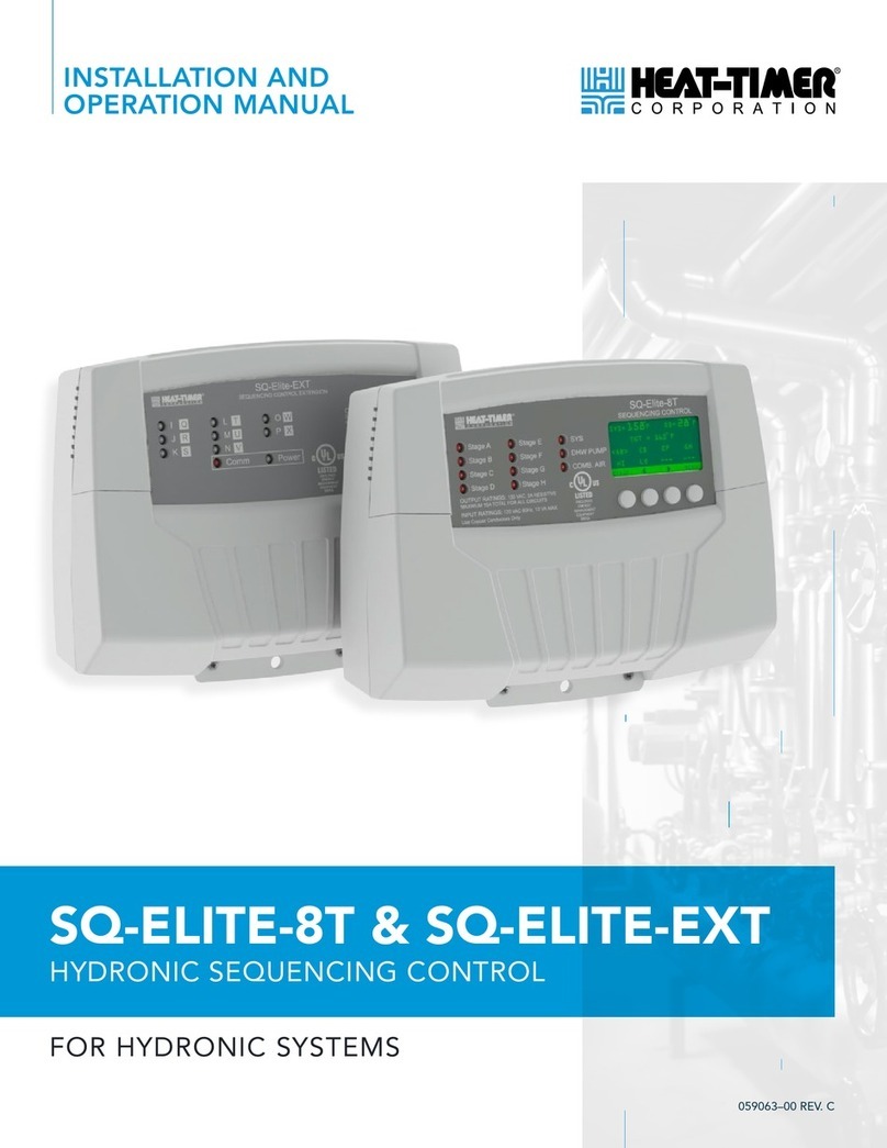
heat-timer TR1000 User manual

HT# 059292-00 F
Motorized Tempering Valves
without Transformers for
2” and 2½” Stainless-Steel Valves
WARNING
This Heat-Timer Motorized Tempering Valve is strictly an operating
valve. It should never be used as a “FailSafe” or “Anti-Scald” valve.
A separate Anti-Scald device can be installed in conjunction with
this motorized tempering valve. All equipment must have their own
certified limit and safety controls required by local codes.
Installation and Operation Manual
ACTUATOR TR1000

HT# 059292-00 F
2Motorized Tempering Valve without Transformer Installation
OVERVIEW
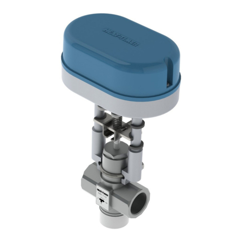
The Heat-Timer electronic tempering valves are 3-way valves. They are components of the Heat-Timer ETV control package.
Though the ETV control is used primarily in domestic hot water temperature regulation, it can be used in other applications as
well. Heat-Timer offers two types of electronic tempering valve actuators: an actuator that requires external power (M800) using
a transformer and an actuator that uses the ETV control 24 VAC power (TR1000). The selection of the actuator depends on the
size and type of valve material selected. This manual demonstrates the actuator using the ETV power source (TR1000) only. This
actuator is used with larger size stainless-steel tempering valves (2” and 2 ½”). These stainless-steel tempering valves are primarily
used in areas adhering to strict Lead-Free codes.
ETV PACKAGES
Bronze ETV
Package
Bronze ETV
Actuator CvValve Size Stainless-steel
ETV Package
Stainless-steel
ETV Actuator Cv
915520-00
Actuator (M800)
Requires External
Power
4.7 ½” 915620-00
Actuator (M800)
Requires External
Power
4.7
915521-00 7.3 ¾” 915621-00 7.3
915522-00 11.6 1” 915622-00 11.6
915523-00 18.5 1-¼” 915623-00 18.5
915524-00 29 1-½ 915624-00 29
915525-00 46.3 2” 915625-00 Actuator (TR1000)
Uses ETV Power
46.3
--- --- 2-½” 915626-00 69
ETV OPERATING CONCEPT
The ETV control modulates the electronic motorized mixing valve to maintain a temperature set point. It does that by mixing two
different water temperatures from two different sources; a hot water source and a cold-water source. The hot water source can be
a hot water boiler, a hot water coil in a steam boiler, or a hot water storage tank. On the other hand, the cold water comes from the
city water system. The cold-water inlet is joined with the circulating loop return pipe to help maintain ow in the valve during no
usage periods. The ETV operation requires the use of a circulating loop pump to maintain a circulating loop temperature.
DESIGN CONSIDERATIONS
CIRCULATING RETURN LOOP
The ETV is designed to operate in a system that has a Circulating Return Loop with a circulating pump. The Circulating Return
Loop temperature must be at least 7°F less than the ETV set point temperature. This temperature differential prevents the mixed
temperature from rising continuously. In addition, the temperature of the hot water entering the valve must be at least 20°F hotter
than the ETV set point temperature.
VERTICAL LOOP
The cold water feeding the hot water supply source MUST have a Thermal Heat Loop. This loop prevents the higher temperature
water in the hot water supply source from backing up and entering the cold-water inlet side of the mixing valve during low ow
periods. The Thermal Heat Loop can be installed either up or down, but must be a minimum of 32 inches as measured from pipe-
center to pipe-center.
Content
Overview. . . . . . . . . . . . . . . . . . . . . . . . . 2
ETV Packages. . . . . . . . . . . . . . . . . . . . . . 2
ETV Operating Concept . . . . . . . . . . . . . . . . 2
Design Considerations . . . . . . . . . . . . . . . . . 2
Valve Installation . . . . . . . . . . . . . . . . . . . . 3
Electronic Tempering Valve Piping . . . . . . . . . . 3
Actuator to Stainless-Steel Valve Assembly . . . . . 4
Wiring the Actuator . . . . . . . . . . . . . . . . . . . 5
Actuator Calibration . . . . . . . . . . . . . . . . . . 5
Dip Switches . . . . . . . . . . . . . . . . . . . . . . 5
Display Messages. . . . . . . . . . . . . . . . . . . . 6
LEDs . . . . . . . . . . . . . . . . . . . . . . . . . . . 6
Troubleshooting . . . . . . . . . . . . . . . . . . . . 6
Warranty . . . . . . . . . . . . . . . . . . . . . . . . . 7
Specifications . . . . . . . . . . . . . . . . . . . . . . 8

HT# 059292-00 F
Motorized Tempering Valve without Transformer Installation 3
ACTUATOR
SIGNAL
SYSTEM= 128oF
TARGET= 130oF
ETV
Control Module
BACK MENU/SET
▼▲
INPUTRATINGS: 120VAC 60HZ, 48VA
▼▲
32” Minimum
Vertical Drop
Thermal Heat
Loop
ETV
Control
ETV
Sensor
Tempered Water
Tempered Water
Circulating Return
Circ. Pump
(Contiuous Running)
Cold Water
Hot Water
HOT
WATER
Actuator
3-way
Valve
Isolation
Valve
ELECTRONIC TEMPERING
VALVE PIPING
VALVE INSTALLATION
1. Close the isolation valve feeding the hot port of the 3-way valve.
2. Pipe the valve. Make sure to follow the port letter designation or
the valve ow direction label.
3. Close the 3-way valve by manually pushing its stem down.
4. The valve and actuator can be mounted vertically or horizontally.
However, they must not be mounted upside down. Hot Port
B
Cold Port
A
Mixed Port
AB
ACTUATOR POWER SWITCH
• The (TR1000) actuator is equipped with a power switch to help in installation and
maintenance.
• The Power Switch must be turned off before assembling the valve and actuator.
• The Power Switch must be turned off prior to manually opening or closing the valve.
WARNING
Every time the actuator is powered on, it will go through a PARTIAL CALIBRATION.
Make sure to close the glove valve feeding the hot port prior to powering the actuator.
Power
Switch

HT# 059292-00 F
4Motorized Tempering Valve without Transformer Installation
ACTUATOR MANUAL OPERATION
2
Switch from
Auto to Manual
Push Handle Down
3
Get ready for
Manual Operation
Flip the Lever
4
Manually Adjust Valve
by Turning Lever
Turn Lever Clockwise
to Close
1
Switch Actuator
Power Off
Power Switch is located
under the Actuator base
5
Switch Actuator
Power On
When done, Turn Actuator
Power Back On
The actuator has a Red Manual Crank Handle to help open or close the valve during assembly or to override automatic operation.
1. Turn the Actuator Power Switch Off.
2. Lower the Red Manual Handle to start the Manual Mode.
3. Flip the lever of the Manual Crank Handle open to open or close the valve.
4. While pressing the handle down, turn the lever clockwise to bring the actuator stem down (Close the Valve). Turning the lever
counter-clockwise bring the actuator stem upwards (Open the Valve).
5. After nishing manual operation, turn the Actuator Power Switch back On.
ACTUATOR TO STAINLESS-STEEL VALVE ASSEMBLY
After installing the valve on the piping system, follow
these instruction to mount the actuator to the valve:
1. Close the isolation valve feeding the hot port of the
3-way valve.
2. Manually close the valve by pushing down on its stem.
3. Turn the actuator power Off using the Power Switch.
4. Manually move the actuator to the open position. See
“Actuator Manual Operation” on page 4.
5. Loosen the Actuator Stem Locking Bracket and remove
the Actuator Body Locking Bracket.
6. Mount the actuator to the valve.
7. Install the Actuator Body Locking Bracket making sure
to align the valve groove with the bracket protrusions.
Secure the bracket in place by tightening its two hex
screws.
8. Gradually, bring the actuator stem down until the valve
stem is aligned with Actuator Stem Locking Bracket.
Then, tighten the bracket’s two hex screws.
9. Turn the actuator Power Switch on. Then wait until the
valve nishes it partial calibration.
10. Calibrate the Actuator to the valve. See “Actuator
Calibration” on page 5.
11. Open the isolation valve feeding the hot port.
WARNING
After assembling the actuator to the valve and
wiring the actuator to the ETV, the actuator
MUST be fully calibrated. Failure to CALIBRATE
the actuator motor before operation may
damage the valve and actuator. Heat-Timer
warranty does not cover these damages
Manual Lever
Actuator
Cover
Calibration Button
Dip Switches
Power
Switch
Valve Flow
Direction Label
Stainless-Steel
3-Way Valve
Actuator Body
Locking Bracket
Actuator Stem
Locking Brackets
Valve
groove
Actuator
Bracket

HT# 059292-00 F
Motorized Tempering Valve without Transformer Installation 5
WIRING THE ACTUATOR
This actuator accepts a 0-10V modulation signal from the ETV control.
In addition, it requires 24 VAC power that is also supplied by the ETV
control.
ACTUATOR MODULATION SIGNAL WIRING
• Wire actuator terminal (E) to ETV terminal (15).
• Wire actuator terminal (O next to the E) to ETV terminal (16).
ACTUATOR POWER WIRING
• Wire actuator terminal (B) to ETV terminal (4).
• Wire actuator terminal (O next to the B) to ETV terminal (3).
• Failure to observe actuator power polarity may damage equipment.
WARNING
To avoid damage to the equipment, DO NOT replace or install
wires when power is connected to the actuator or the control.
▼▲
24VAC
4-20mA
Set Point
Shutdown Setback Sys
Temp
Aux
Temp Voltage 1 Voltage 2 4-20mA Auxiliary
~~+-+-+-+-
Output
34 5 6 7 8 9 10 11 12 13 14 15 16 17 18 19 20 21 22
YEOOB
Actuator Accepts
0-10 Voltage Signal
0-10V Modualting
Voltage Signal
24 VAC
Actuator Power
ACTUATOR CALIBRATION
RED PUSH BUTTON
WARNING
After assembling the actuator to the valve and wiring the actuator
to the ETV, the actuator MUST be fully calibrated. Failure to
CALIBRATE the actuator before operation may damage the valve and
actuator. Heat-Timer warranty does not cover these damages
Each time the actuator is assembled to the valve, the actuator must be calibrated using the
following steps:
1. Close the isolation valve feeding the tempering valve hot port.
2. Make sure that the actuator Power Switch is set to On.
3. Power the actuator. See ETV installation manual.
4. Start the calibration by holding down the Calibration Button for over 3 seconds. The
actuator will fully open and then fully close the valve. During this process, both LEDs
will blink at the same time.
5. When the actuator returns to its normal operating position, the calibration has ended.
6. Open the isolation valve feeding the tempering valve hot port.
Calibration Button
DIP SWITCHES
The actuator dip switches are preset in the factory. However, it is important to have the
factory settings when troubleshooting.
•. All dip switches are set to Off except for Dip Switch 6 and 8 that are set to ON.
Dip Switches

HT# 059292-00 F
6Motorized Tempering Valve without Transformer Installation
DISPLAY MESSAGES
• This actuator has a 4 letter alphanumeric display.
• Under normal operation, the left most letter will be followed by a number. The
character can be either a “C” or an “F”.
• The letter “C” represents the current input signal. Example: C 97.
• The letter “F” represents the current valve position . Example: F 98.
• The actuator will alternate the display of both C and E values.
• When “ERR “ is displayed, it indicates an error in the actuator positioning. In this
case, the actuator needs to be re-calibrated.
LEDS
• The LEDs indicate the actuator movement direction.
• When the actuator is being calibrated, both LEDS will blink at the same time until
the process ends.
• The White LED is lit when the actuator opens the valve.
• The Red LED is lit when the actuator closes the valve.
LEDs
TROUBLESHOOTING
Valve calibrates but does not move afterwards
• Check the modulation signal wiring to the actuator (terminals O and E). If the modulation signal wiring is not connected or is
wired incorrectly, the valve will not move after calibration. See “Wiring the Actuator” on page 5.
• Check the modulation signal value. It may be that the modulation signal matches the valve location after calibration. See
“Display Messages” on page 6.
• Check the AC voltage going to the actuator. The actuator is designed to work between 19 and 26 VAC. If the voltage above or
below this range the valve may stop responding to the modulation signal.
Valve does not move
• Make sure that there is power going to the actuator (terminals B and O). The actuator power is polarity sensitive.
• The valve may be jammed with debris. This can be tested by removing the actuator and testing the valve movement manually by
pushing and pulling on the valve stem.
• If the previous tests proved no problems, then the actuator may need to be replaced.
Actuator Display Reads ‘ERR’
• Re-calibrate the actuator to the valve. See “Actuator Calibration” on page 5. If the problem persists, contact the factory.

HT# 059292-00 F
Motorized Tempering Valve without Transformer Installation 7
WARRANTY
WARRANTIES AND LIMITATIONS OF LIABILITY AND DAMAGE: Heat-Timer Corporation warrants that it will replace,
or at its option, repair any Heat-Timer Corporation manufactured product or part thereof which is found to be defective in
material workmanship within one year from the date of installation only if the warranty registration has been properly lled out
and returned within 30 days of the date of installation. Damages to the product or part thereof due to misuse, abuse, improper
installation by others or caused by power failure, power surges, re, ood or lightning are not covered by this warranty. Any
service, repairs, modications or alterations to the product not expressly authorized by Heat-Timer Corporation will invalidate
the warranty. Batteries are not included in this warranty. This warranty applies only to the original user and is not assignable or
transferable. Heat-Timer Corporation shall not be responsible for any maladjustments of any control installed by Heat-Timer
Corporation. It is the users responsibility to adjust the settings of the control to provide the proper amount of heat or cooling
required in the premises and for proper operation of the heating or cooling system. Heat-Timer Corporation shall not be required
to make any changes to any building systems, including but not limited to the heating system, boilers or electrical power system,
that is required for proper operation of any controls or other equipment installed by Heat-Timer Corporation or any contractor.
Third Party products and services are not covered by this Heat-Timer Corporation warranty and Heat-Timer Corporation makes
no representations or warranties on behalf of such third parties. Any warranty on such products or services is from the supplier,
manufacturer, or licensor of the product or service. See separate Terms and Conditions of Internet Control Management System
(“ICMS”) services, including warranties and limitations of liability and damages, for ICMS services.
THE FOREGOING IS IN LIEU OF ALL OTHER WARRANTIES, EXPRESS OR IMPLIED AND HEAT-TIMER
CORPORATION SPECIFICALLY DISCLAIMS ANY AND ALL WARRANTIES OF MERCHANTABILITY FOR A
PARTICULAR PURPOSE. UNDER NO CIRCUMSTANCES SHALL HEAT-TIMER CORPORATION, ITS AUTHORIZED
REPRESENTATIVES, AFFILIATED OR SUBSIDIARY COMPANIES BE LIABLE FOR SPECIAL, CONSEQUENTIAL
OR INCIDENTAL DAMAGES, EXCEPT AS SPECIFICALLY STATED IN THESE TERMS AND CONDITIONS OF
SALE. THE SOLE REMEDY WITH RESPECT TO ANY PRODUCT OR PART SOLD OR INSTALLED BY HEAT-TIMER
CORPORATION SHALL BE LIMITED TO THE RIGHT TO REPLACEMENT OR REPAIR F.O.B. FAIRFIELD, NJ.
HEAT-TIMER CORPORATION SHALL NOT BE LIABLE OR RESPONSIBLE FOR LOSS OR DAMAGE OF ANY KIND
RESULTING FROM DELAY OR INABILITY TO DELIVER FOR ANY REASON, INCLUDING BUT NOT LIMITED TO
FIRE, FLOOD, LIGHTNING, POWER FAILURE OR SURGES, UNAVAILABILITY OF PARTS, STRIKES OR LABOR
DISPUTES, ACCIDENTS AND ACTS OF CIVIL OR MILITARY AUTHORITIES.
03122010

HT# 059292-00 F
8Motorized Tempering Valve without Transformer Installation
20 New Dutch Lane, Faireld, NJ 07004
Ph: (973) 575-4004 • Fax: (973) 575-4052
http://www.heat-timer.com
SPECIFICATIONS
TR1000 ACTUATOR
Voltage Input: . . . . . . . . . . . . . . . . . . . . . . . . . . . . . . . . . . . . . . . . . . . . . . . . . . . . 19 to 26 VAC 60 Hz
Power Consumption: . . . . . . . . . . . . . . . . . . . . . . . . . . . . . . . . . . . . . . . . . . . . . . . . . . . . . 12 VA Max
Operating Temperature . . . . . . . . . . . . . . . . . . . . . . . . . . . . . . . . . . . . . . . . . from 14°F/-10°C to 122°F/50°C
Force . . . . . . . . . . . . . . . . . . . . . . . . . . . . . . . . . . . . . . . . . . . . . . . . . . . . . . . . . . . .225 Lbf/1000N
Valve Input Signal: . . . . . . . . . . . . . . . . . . . . . . . . . . . . . . . . . . . . . . . . . . . . . . . . . . . . . . . . 0-10V
Manual Override . . . . . . . . . . . . . . . . . . . . . . . . . . . . . . . . . . . . . . . . . . . . . . . . . . Manual Crank Handle
Clearance. . . . . . . . . . . . . . . . . . . . . . . . . . . . . . . . . . Minimum of 4- 6” above the actuator for manual operation
Bracket . . . . . . . . . . . . . . . . . . . . . . . . . . . . . . . . . . . . . . . . . . . . . . . . . . . . . . . . Die-Cast Aluminum
Dimensions: . . . . . . . . . . . . . . . . . . . . . . . . . . . . . . . . . . . . . . . . . . . . . . . . . 7 ⅛”W x 12 ¾”H x 7 ½L”
Weight: . . . . . . . . . . . . . . . . . . . . . . . . . . . . . . . . . . . . . . . . . . . . . . . . . . . . . . . . . . . . . 11 pound
STAINLESS-STEEL VALVE
Valve Type: . . . . . . . . . . . . . . . . . . . . . . . . . . . . . . . . . . . . . . . . . . . . . . . . . . . . . . . . 3-way Mixing
Valve Sizes: . . . . . . . . . . . . . . . . . . . . . . . . . . . . . . . . . . . . . . . . . . . . . . . . . . . . . . . . . . 2” and 2½”
Body and Trim Material: . . . . . . . . . . . . . . . . . . . . . . . . . . . . . . . . . . . . . . . . . . . . . . . 304 Stainless Steel
Stem Material: . . . . . . . . . . . . . . . . . . . . . . . . . . . . . . . . . . . . . . . . . . . . . . . . . . . . 304 Stainless Steel
Maximum Temperature: . . . . . . . . . . . . . . . . . . . . . . . . . . . . . . . . . . . . . . . . . . . . . . . . . . 180°F/82°C
Maximum Pressure: . . . . . . . . . . . . . . . . . . . . . . . . . . . . . . . . . . . . . . . . . . . . . . . . . . . . . . . 225 psi
Port Connection: . . . . . . . . . . . . . . . . . . . . . . . . . . . . . . . . . . . . . . . . . . . . . . . . . . . . . NPT Threaded
Valve Ports: . . . . . . . . . . . . . . . . . . . . . . . . . . . . . . . . . . . . . . A (Cold inlet), B (Hot inlet), AB (Mixed outlet)
Table of contents
Other heat-timer Controllers manuals
