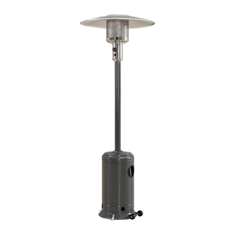
Heatmaxx SRPH98 User manual

2ZQHUV0DQXDO
4XHVWLRQVSUREOHPVPLVVLQJUHSODFHPHQWSDUWV"Before returning to your retailer
call our customer service department at 1-888-909-3888, between 7:30am and 4:30pm
PST, Monday through Friday.
,I\RXVPHOOJDV
6KXWRIIJDVWRWKHDSSOLDQFH
([WLQJXLVKDQ\RSHQIODPH
,IRGRUFRQWLQXHVNHHSDZD\IURP
WKHDSSOLDQFHDQGLPPHGLDWHO\FDOO
\RXUJDVVXSSOLHURUILUHGHSDUWPHQW
'RQRWVWRUHRUXVHJDVROLQHRU
RWKHUIODPPDEOHYDSRUVDQGOLTXLGV
LQWKHYLFLQLW\RIWKLVRUDQ\RWKHU
DSSOLDQFH
$Q/3F\OLQGHUQRWFRQQHFWHGIRU
XVHVKDOOQRWEHVWRUHGLQWKHYLFLQLW\
RIWKLVRUDQ\RWKHUDSSOLDQFH
'$1*(5
'$1*(5
:$51,1*
)RU2XWGRRU8VH2QO\
CAUTION:
Installer: Leave the manual instructions
to the user for future use.
Consumer: Please keep this manual
for future reference.
Model#: SRPH98
Read the instructions before use.
This appliance must be installed in
accordance with such regulations as
are in force.
3<5$0,'3$7,2+($7(5
0RGHO653+
,QVWUXFWLRQV0DQXDO

:$51,1*6$1'&$87,216
7KLVDSSOLDQFHFDQSURGXFHFDUERQPRQR[LGH
ZKLFKKDVQRRGRU
8VLQJLWLQDQHQFORVHGVSDFHFDQNLOO\RX
1HYHUXVHWKLVDSSOLDQFHLQDQHQFORVHGVSDFHVXFK
DVDFDPSHUWHQWRUKRPH
'$1*(5 &$5%210212;,'(+$=$5'
:$51,1* ,PSURSHULQVWDOODWLRQDGMXVWPHQWDOWHUDWLRQVHUYLFHRPDLQWHQDQFHr
FDQFDXVHSURSHUW\GDPDJHLQMXU\RUGHDWK5HDGWKHLQVWDOODWLRQRSHUDWLQJDQG
PDLQWHQDQFHLQVWUXFWLRQVWKRURXJKO\EHIRUHLQVWDOOLQJRUVHUYLFLQJWKLVHTXLSPHQW
63(&,),&$7,21
Certification
Height
Rated heat input
Fuel
Gas Supply
Manifold pressure
Safety features
UL
89.5" (2.27m)
40,000 BTU/hr
Propane rednilycsagPL)gk9(bl02 .C.W"11 hctiwstlit-itna,ecivederuliafemalF
Max. 250 PSI, Min. 5 PSI
Gas supply pressure
2

:$51,1*6$1'&$87,216
The installation must conform with local codes
or, in the absence of local codes, with the
National Fuel Gas Code, ANSI Z223.1/NFPA54,
NFPA58 Natural Gas and Propane Installation
Code, CSA B149.1, or Propane Storage and
Handling Code, B149.2
The heater, when installed, must be electrically
grounded in accordance with local codes or, in
the absence of local codes, with the National
Electrical Code, ANSI/NFPA70, or the Canadian
Electrical Code, CSA C22.1.
&KLOGUHQDQGDGXOWVVKRXOGEHDOHUWHGWR
WKHKD]DUGVRIKLJKVXUIDFHWHPSHUDWXUHV
DQG VKRXOG VWD\ DZD\ WR DYRLG EXUQV RU
FORWKLQJLJQLWLRQ
<RXQJ FKLOGUHQ VKRXOG EH FDUHIXOO\
VXSHUYLVHG ZKHQ WKH\ DUH LQ WKH DUHD RI
WKHKHDWHU
&ORWKLQJ RU RWKHU IODPPDEOH PDWHULDOV
VKRXOG QRW EH KXQJ IURP WKH KHDWHU RU
SODFHGRQRUQHDUWKHKHDWHU
Prior to use, check for damaged parts such as
hoses, regulators, pilot or burner.
All leak tests should be done with a soapy solu-
tion. NEVER USE AN OPEN FLAME TO
CHECK FOR LEAKAGE.
The propane hose with regulator assembly shall
be located out of pathways where people may
trip over it or in areas where the hose will not be
subject to accidental damage.
$Q\ JXDUG RU RWKHU SURWHFWLYH GHYLFH
UHPRYHGIRUVHUYLFLQJWKHKHDWHUPXVWEH
UHSODFHGSULRUWRRSHUDWLQJWKHKHDWHU
,QVWDOODWLRQDQGUHSDLUVKRXOGEHGRQHE\
D TXDOLILHG VHUYLFH SHUVRQ 7KH KHDWHU
VKRXOG EH LQVSHFWHG EHIRUH XVH DQG DW
OHDVW DQQXDOO\ E\ D TXDOLILHG VHUYLFH
SHUVRQ
0RUH IUHTXHQW FOHDQLQJ PD\ EH UHTXLUHG
DVQHFHVVDU\,WLVLPSHUDWLYHWKDWFRQWURO
FRPSDUWPHQWEXUQHUVDQGFLUFXODWLQJDLU
SDVVDJHZD\VRIWKHKHDWHUEHNHSWFOHDQ
Keeping the appliance area clear and free from
combustible materials, gasoline and other flam-
mable vapors and liquids.
Not obstructing the flow of combustion and venti-
lation air.
Keeping the ventilation opening(s) of the cylin-
der enclosure free and clear from debris.
This appliance shall be used only in a well-
ventilated space and shall not be used in a build-
ing, garage or any other enclosed area.
An appliance may be installed with shelter no
more inclusive than:
With walls on all sides, but with no overhead
cover.
Within a partial enclosure which includes an
overhead cover and no more than two side
walls. These side walls may be parallel, as in a
breezeway, or at right angles to each other.
127(3/($6(5($'7+()2//2:,1*6$)(7<58/(6
:$51,1*
3

:$51,1*6$1'&$87,216
The pressure regulator and hose assembly sup-
plied with the appliance must be used, replace-
ment pressure regulators and hose assemblies
must be those specified by the appliance manu-
facturer.
Do not store a spare LP-gas cylinder under or
near this appliance;
Never fill the cylinder beyond 80 percent full;
Do not clean the heater with cleaners that are
combustible or corrosive.
127(3/($6(5($'7+()2//2:,1*6$)(7<58/(6
Place the dust cap on the cylinder valve outlet
whenever the cylinder is not in use. Only install
the type of dust cap on the cylinder valve that is
provided with the cylinder valve. Other types of
caps or plugs may result in leakage of propane.
Within a partial enclosure which includes an
overhead cover and three side walls, as long as
30 percent or more of the horizontal periphery of
the enclosure is permanently open.
This appliance requires 9kg(20lb) LP-gas supply
cylinder.
The LP-gas supply cylinder to be used must be:
Constructed and marked in accordance with the
Specifications for LP-gas cylinders of the U.S.
Department of Transportation (DOT); or the
Standard for Cylinders, Spheres and Tubes for
Transportation of Dangerous Goods and Com-
mission, CAN/CSA-B339, as applicable;
Provided with a listed overfilling prevention
device; and provided with a cylinder connection
device compatible with the connection for the
appliance.
Ensure that the cylinder is disconnected when the
appliance is not in use.
Storage of an appliance indoors is permissible
only if the cylinder is disconnected and removed
from the appliance.
A cylinder must be stored outdoors in a well-
ventilated area out of the reach of children. A
disconnected cylinder must have dust caps
tightly installed and must not be stored in a build-
ing, garage or any other enclosed area.
Appliance may shut down in windy conditions in
excess of 3 miles per hour (4.83 kilometers per
hour).
:$51,1*
Certain materials or items, when stored under
the heater, will be subjected to radiant heat and
could be seriously damaged.
Inspect the visible portion of the hose before
each use of the appliance and inspect the entire
hose assembly at lease annually.
The cylinder used must include a collar to protect
the cylinder valve.
Installation of this appliance at altitudes above
2000 ft (610m) shall be in accordance with local
codes, or in the absence of local codes, ANSI
Z223.1/NFPA 54 or CSA B149.1.
4

:$51,1*6$1'&$87,216
This heater is designed to operate with a standard 20 Ib propane cylinder with Approved Cylinder
Connection.
127(3/($6(5($'7+()2//2:,1*6$)(7<58/(6
722/61(('('
Adjustable open end wrench (NOT INCLUDED)
Philips screwdriver
Estimated time for assembly: 30 minutes.
35(3$5$7,21
Before beginning assembly of product, make sure all parts are present. If any part is missing or
damaged, do not attempt to assemble the product. Contact customer service for replacement parts.
Every part of the heater shall be secure against displacement and shall be constructed to maintain
a fixed relationship between essential parts under normal and reasonalbe conditions of handling and
usage. Parts not permanently secured shall be designed so they cannot be incorrectly assembled
and cannot be improperly located or misaligned in removing or replacing during cleaning or other
servicing.
Perform a leak test with a soapy solution:
1. To check gas connections.
2. After connecting a new cylinder.
3. Upon re-assembly after disassembly.
5
This product can expose you to chemicals including Lead and Lead Compounds, which are
known to the state of California to cause cancer, and Carbon Monoxide, Lead and Lead
Compounds which are known to the state of California to cause birth defects or other
reproductive harm. For more information go to www.P65Warnings.ca.gov
WARNING

(;3/2'('9,(:

3$576+$5':$5(
Part # Description Picture Qty Part # Description Picture Qty
Reflector M5 Wing Nut
M5 Bolt
M5 x 12 Screw
M4 x 25 Screw
(pre-assembly)
M8 x 10 Screw
(pre-assembly)
8.5 Washer
(pre-assembly)
M4 x 10 Screw
(pre-assembly)
Philips
screwdriver
AA
BB
CC
DD
EE
FF
GG
HH
II
1
2
3
4
5
6
7
8
9
10
11
12
13
14
15
16
17
1
1
4
1
1
1
1
1
4
1
1
1
4
2
1
1
1
3
3
68
4
4
3
1
3
Mesh
Spiral
Burner Assembly
Back Panel
Gas Cylinder Holder
Fire Damper
Upper Support
Glass Tube
Glass Tube Base
Middle Plate
Lower Support
Left and Right Panel
Front Panel
Bottom Plate
Wheel Assembly
Upper Plate
JJ
KK
LL
1MM
M8 Nut
(pre-assembly) 3
M5 Stud 3
M5 Nut 3
1
Guard Bracket
Handle
7

$66(0%/<,16758&7,216
II
KK
JJ
16
17
13
CC 16
6WHS
Unscrew the pre-assembled screws, nuts and washers on the wheel assembly (#17), then attach the wheel
assembly (#17) to the bottom plate (#16) with (3) M8 x 10 screws (II), (3) M8 nuts (JJ) and (3) 8.5 washers
(KK) as illustrated.
6WHS
Attach (4) lower supports (#13) to the bottom plate (#16) with (12) M5 x 12 screws (CC) as illustrated.
+DUGZDUH8VHG
M8 Nut
(pre-assembly)
M8 x 10 Screw
(pre-assembly)
3 pcs
3 pcs
II
JJ
8.5 Washer
(pre-assembly)
3 pcs
KK
+DUGZDUH8VHG
M5 x 12 Screw 12 pcs
CC

12
9
CC
CC
$66(0%/<,16758&7,216
9
11
12
12
13
13
HH
6WHS
Unscrew the pre-assembled M4 x 25 screws (HH) on the glass tube base (#11), then remove the glass tube
base (#11) from the middle plate (#12), and put the M4 x 25 screws (HH) and the glass tube base (#11) aside
for Step 7.
Attach the middle plate (#12) to the lower supports (#13) with (8) M5 x 12 screws (CC) as illustrated.
6WHS
Attach (4) upper supports (#9) to the lower supports (#13) with (16) M5 x 12 screws (CC) as illustrated.
+DUGZDUH8VHG
M5 x 12 Screw 8 pcs
CC
+DUGZDUH8VHG
M5 x 12 Screw 16 pcs
CC

2
8
CC
2
9
1
AA
BB
FF
DD
$66(0%/<,16758&7,216
10
6WHS
Attach the upper plate (#2) to the upper supports (#9) with (8) M5 x 12 screws (CC) as illustrated.
6WHS
Attach the fire damper (#8) to the upper plate (#2) with (3) M5 bolts (FF) and (3) M5 nuts (DD), then attach
the reflector (#1) to the fire damper (#8) with (3) M5 wing nuts (AA) and (3) M5 studs (BB) as illustrated.
+DUGZDUH8VHG
M5 x 12 Screw 8 pcs
CC
+DUGZDUH8VHG
M5 Wing Nut 3 pcs
AA
M5 Stud 3 pcsBB
M5 Bolt 3 pcsFF
M5 Nut 3 pcsDD
1. 2.

5
11
CC
HH
12
4
CC
5
$66(0%/<,16758&7,216
12
11
6WHS
Attach the glass tube base (#11) to the middle plate (#12) with (4) M4 x 25 screws (HH) as illustrated.
6WHS
Attach the spiral (#4) to the burner assembly (#5) with (2) M5 x 12 screws (CC), then attach the burner
assembly (#5) to the middle plate (#12) with (4) M5 x 12 screws (CC) as illustrated.
+DUGZDUH8VHG
+DUGZDUH8VHG
M5 x 12 Screw 6 pcs
CC
M4 x 25 Screw
(pre-assembly)
4 pcsHH

6
7
14
CC
CC
6
13
$66(0%/<,16758&7,216
6WHS
Attach the gas cylinder holder (#7) to the back panel (#6) with (2) M5 x 12 screws (CC) as illustrated
6WHS
Attach the back panel (#6), left and right panel (#14) to the lower supports (#13) with (12) M5 x 12 screws
(CC) as illustrated.
+DUGZDUH8VHG
M5 x 12 Screw 2 pcs
CC
+DUGZDUH8VHG
M5 x 12 Screw 12 pcs
CC

10
Guard Bracket
$66(0%/<,16758&7,216
13
6WHS
Place the glass tube (#10) by guiding it up to insert the upper end through the center hole in the upper plate.
Do not force the tube. Slide the bottom end into place and settle it into the hole in the glass tube base.
Ensure that the Glass Tube is positioned properly to cover the spiral.
6WHS
Attach (4) meshes (#3) to the upper supports with (4) M5 x 12 screws (CC) and (4) guard brackets (EE)
as illustrated.
+DUGZDUH8VHG
M5 x 12 Screw 4 pcs
CC
4 pcsEE
CC
EE

$66(0%/<,16758&7,216
14
6WHS
Unscrew the pre-assembled M4 x 10 screw (LL) on the handle (GG), then attach the handle (GG) to the front
panel (#15) with M4 x 10 screw (LL).
Install the front panel (#15) by inserting the two tabs at the bottom into the holes
on the front of the bottom plate (#16). Attach the chain between inside of the door
handle and the front of the burner assembly, then close the panel. The panel
secures with magnet.
127(The chain is used to support the front panel while operating the controls.
+DUGZDUH8VHG
M4 x 10 Screw
(pre-assembly)
1 pc
LL
Handle 1 pcGG
GG
LL

$66(0%/<,16758&7,216
15
6WHS
When installing an LPG cylinder, it may be easier to remove the Front Panel completely and set aside.
Place the cylinder on the Bottom Plate. Connect the gas hose to 20lb LPG cylinder (not included).
Screw the regulator to the cylinder as illustrated. Tighten securely with the Fastening Belt.
127(The regulator with gas hose is supplied.

&KHFNIRUOHDNV
All connection on the patio heater have been
checked for leakage at the factory. Follow these
steps to check the gas hose/regulator/cylinder
connections:
1) Make leakage solution by mixing 1 part liquid
dish soap and 3 parts water.
2) Spoon or brush several drops (or use squirt
bottle) of the solution onto hose connection,
regulator & cylinder connection.
3) Turn on gas cylinder valve. Inspect the
connections and look for bubbles.
4) If no bubbles appear, the connection is safe.
5) If bubbles appear, there is leakage. Loosen
and re-tighten this connection. If connection
still leaks, please call customer service:
1-888-909-3888
1RWH
1) The cylinder supply system must be arranged
for vapor withdrawal;
2) The cylinder used must include a collar to
protect the cylinder valve.
6$)(7<&+(&.
:$51,1*21/<$1$87+25,=('*$67(&+1,&,$16+28/',167$//7+,6352'8&7
16
brush
P1 P3
P2
brush

Unscrew the cap of the igniter placed on the control box and
insert the included AAA battery with the POSITIVE end facing out.
:$51,1*'2127$77(0377223(5$7(7+($33/,$1&(817,/<28+$9(
5($'$1'81'(567$1'$//35(&$87,216)$,/85(72'262&$15(68/7,1
3523(57<'$0$*(6(5,286,1-85<25'($7+
17

)ODPH&KDUDFWHULVWLF
The flame pattern at the emitter screen should
be visually checked whenever heater is operated.
Normally the burner flame is yellow
If flames extend beyond surface of the emitter
grid, or the phenomena of flame lift or light back,
or black spot is accumulating on the emitter grid
or reflector, the heater should be WXUQHGRII
immediately. The heater should not be operated
again until the unit is serviced and or repaired.
These lighting instructions must be
followed. An unsafe condition can
occur if they are not followed correctly.
23(5$7,21
18
1. Make sure control knob is in the “OFF”
position.
2. Turn LP cylinder gas valve to fully open
position.
3. Push in control knob and turn
counter-clockwise to "IGNITE" position, at
the same time push in the ignition button
and keep the control knob depressing until
lighting the burner.
4. If the burner is lit,keep press down the ignition
button for 30 seconds before releasing control
knob.
5. If the burner is not lit,press down the control
knob and turn clockwise to “OFF” position,
repeat from step 3 after 5 minutes.
6. When burner is lit, turn the control knob to
desired heat output position between "LOW"
and "HIGH".
7. Press down and turn the control knob
clockwise to "OFF" position to shut down the
appliance.
Turn off cylinder gas valve.
IGNITE
P
u
s
h
t
o
t
u
r
n
I
G
N
I
T
E
/
L
O
W
O
F
F
H
I
G
H

0LQLPXP FOHDUDQFH IURP FRPEXVWLEOH
VXUIDFHV
This heater is primarily used for the heating
of outdoor patios, decks, spas, pools and
open working areas.
Combustible materials are considered to be
wood, compressed parter, plant fibres, plas-
tic or other materials that are capable of
being ignited and burned.
Always make sure that adequate fresh air
ventilation is provided. Follow the spacing
tolerances shown in the following figure right
at all times.
This heater must be placed on level, firm
ground.
Never operate in an explosive atmosphere.
Keep away from areas where gasoline or
other flammable liquids or vapors are stored
or used.
/2&$7,216$)(7<,1)250$7,21
24''24''
36''
19

0$,17(1$1&(6725$*(
DO NOT touch or move heater for
at least 45 minutes after use. Allow
all burner elements to cool before
touching.
FOR YOUR SAFETY ;
WARNING:
127(
In a salt-air environment (such as
near an ocean). corrosion occurs
more quickly than normal.
Frequently check for corroded
areas and repair them promptly.
127(
wait until heater is cool before
covering.
&/($1,1*$1'0$,17(1$1&(
To enjoy years of outstanding performance from your
heater make sure you perform the following maintenance
activities on a regular basis:
Keep exterior surfaces clean.
Use warm soapy water for cleaning. Never use
flammable of corrosive cleaning agents.
While washing your unit, be sure to keep the area
around the burner and pilot assembly dry at all times. If
the gas control is exposed to water in any way, do NOT
try to use it. It must be replaced.
Keep the appliance area free and clean from combustible
materials, gasoline and other flammable vapors and
liquids; not obstructing the flow of combustion and
ventilation air; keeping the ventilation opening(s) of the
cylinder enclosure free and clear from debris.
Gas odor with extreme yellow tipping of flame.
Heater does NOT reach the desired temperature.
Heater glow is excessively uneven.
Heater makes popping noises.
Visually checking burner flames.
Cleaning the appliance, including special surfaces, with
recommended cleaning agents, if necessary.
Lubrication of moving parts and the type and amount of
lubricant to be used.
When applicable, visually checking portions of the hose
assembly located within the confines of the heater post.
Check if there are cracks or worn sections on hose. If
yes, please call our customer service to replace hose.
$WOHDVWRQFHD\HDUWKHXQLWVKRXOGEHLQVSHFWHG for
the presence of spiders, spider webs or other insects.
Air flow must be unobstructed. Keep controls, burner,
and circulating air passageways clean. Signs of possible
blockage include:
Check the cracks or worn sections
20
Other Heatmaxx Patio Heater manuals
Popular Patio Heater manuals by other brands

HEAT1
HEAT1 ECO pro-line 2000W instructions

Hiland
Hiland HLI-1531 owner's manual

La Proromance
La Proromance HSS-A user manual

Outback
Outback OUT370663/PH500 Assembly and operating instructions

Endless Summer
Endless Summer ENDLESS SUMMER WK-INS-100 E user manual

Berner
Berner Deco-Tube Series Installation, operating and service instructions

Lifestyle
Lifestyle Aurora 2 Assembly and operating instructions

Dancover
Dancover HE94020 Safety instructions and operation manual

sunjoe
sunjoe 48000 BTU MAX Operator's manual

BlueRhino
BlueRhino Endless Summer 235000 owner's manual

Firesense
Firesense steel pagoda Assembly instructions

Comfortaire
Comfortaire IRPH15SS Comfort Aire Installation & operation manual