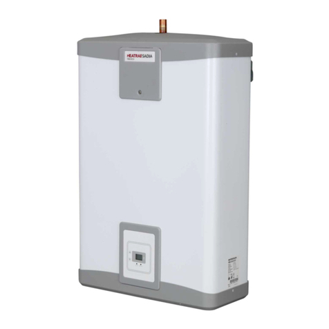
Heatrae Sadia Megaflo solar Instruction Manual
Other Heatrae Sadia Water Heater manuals

Heatrae Sadia
Heatrae Sadia SUPREME 220SS User manual

Heatrae Sadia
Heatrae Sadia PremierPlus PES170D User manual

Heatrae Sadia
Heatrae Sadia 7 Litre 1kW User manual
Heatrae Sadia
Heatrae Sadia Express 50 Litres User manual

Heatrae Sadia
Heatrae Sadia SUPREME 150 Instruction Manual

Heatrae Sadia
Heatrae Sadia PremierPlus User manual

Heatrae Sadia
Heatrae Sadia sadia megalife he User manual

Heatrae Sadia
Heatrae Sadia Hotflo 10 User manual

Heatrae Sadia
Heatrae Sadia Megaflo Eco SolaReady User manual

Heatrae Sadia
Heatrae Sadia SUPREME 150SS User manual
Heatrae Sadia
Heatrae Sadia EXPRESS 7/1 User manual

Heatrae Sadia
Heatrae Sadia SUPREME 220SS User manual
Heatrae Sadia
Heatrae Sadia MegaLife HE Series User manual

Heatrae Sadia
Heatrae Sadia Megaflo Eco Solar Series User manual
Heatrae Sadia
Heatrae Sadia Multipoint Instantaneous User manual

Heatrae Sadia
Heatrae Sadia STREAMLINE OVERSINK User manual

Heatrae Sadia
Heatrae Sadia MULTIPOINT 10 Guide

Heatrae Sadia
Heatrae Sadia ELECTROMAX SOLAR Release note
Heatrae Sadia
Heatrae Sadia Multipoint ECO Operator's manual

Heatrae Sadia
Heatrae Sadia STREAMLINE OVERSINK 95010283 User manual
Popular Water Heater manuals by other brands

clage
clage German pool CEX13 operating instructions

Noritz
Noritz proTough NR98SV installation manual

DeDietrich
DeDietrich KALIKO TWH 200 EV Installation and service manual

veito
veito FLOW Installation and operating instructions

ICI Caldaie
ICI Caldaie COSMOGAS AGUATANK 150 Instructions for installation, use and maintenance manual

Savio
Savio Laser 11 A Instruction manual for installation and use

Kenmore
Kenmore 153.582400 Use & care guide

STIEBEL ELTRON
STIEBEL ELTRON Eltronom SHU 5 S Operating and installation instructions

clage
clage E-Mini Series Operating and installation instructions

Solar
Solar SunX 317365-002 instruction manual

Bradford White
Bradford White EF Series Service manual

Dimplex
Dimplex ECSd125-580 Installation and user instructions

Dux
Dux 32FCR6N installation manual

Noritz
Noritz N-132M Owner's guide and installation manual

TESY
TESY GCV7/4S 10047 Instructions for use and maintenance

A.O. Smith
A.O. Smith Gphe 50 instruction manual

Rinnai
Rinnai REP199i Installation and operation manual

Toyotomi
Toyotomi Oil Miser OM-148 (Type D) Operation and maintenance instructions


