Heatrae Sadia EXPRESS 7/1 User manual
Other Heatrae Sadia Water Heater manuals

Heatrae Sadia
Heatrae Sadia Megaflo Eco SystemFit 145sf User manual

Heatrae Sadia
Heatrae Sadia MegaFlo User manual

Heatrae Sadia
Heatrae Sadia SUPREME 150 Instruction Manual

Heatrae Sadia
Heatrae Sadia Megaflo Eco 70i User manual

Heatrae Sadia
Heatrae Sadia SUPREME 220SS User manual

Heatrae Sadia
Heatrae Sadia PremierPlus User manual

Heatrae Sadia
Heatrae Sadia STREAMLINE OVERSINK 95010283 User manual
Heatrae Sadia
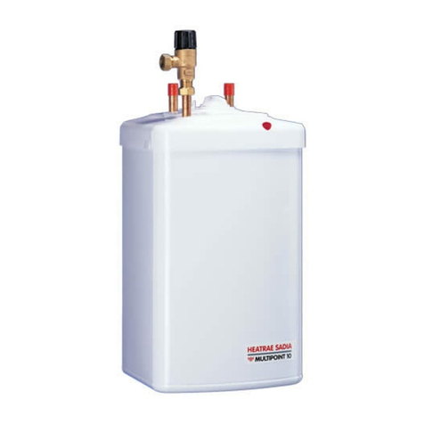
Heatrae Sadia MULTIPOINT 10 Guide

Heatrae Sadia
Heatrae Sadia STREAMLINE OVERSINK User manual

Heatrae Sadia
Heatrae Sadia Multipoint 30 Guide
Heatrae Sadia
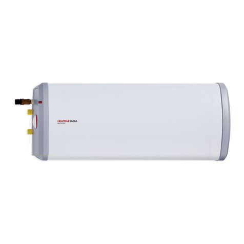
Heatrae Sadia Multipoint 30H User manual

Heatrae Sadia
Heatrae Sadia MegaFlo User manual
Heatrae Sadia
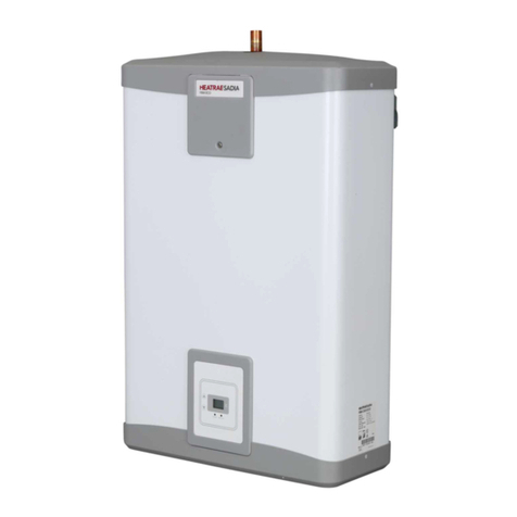
Heatrae Sadia FBM ECO User manual

Heatrae Sadia
Heatrae Sadia 7 Litre 1kW User manual

Heatrae Sadia
Heatrae Sadia Hotflo 10 User manual
Heatrae Sadia
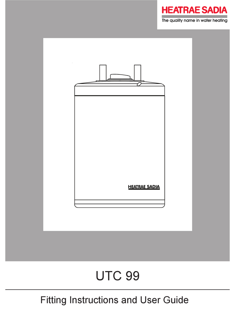
Heatrae Sadia UTC 99 User manual

Heatrae Sadia
Heatrae Sadia Streamline User manual

Heatrae Sadia
Heatrae Sadia Aquatap Boil and Chill User manual

Heatrae Sadia
Heatrae Sadia Megaflo Eco Solar Series User manual
Heatrae Sadia
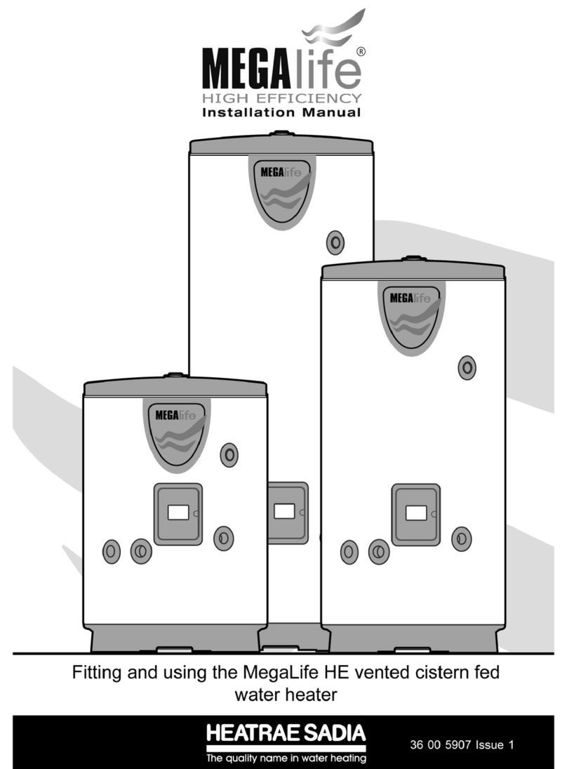
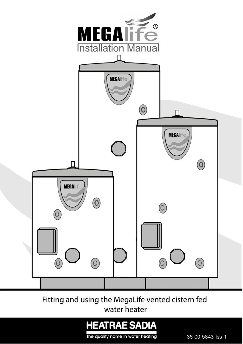
Heatrae Sadia MegaLife HE Series User manual
Popular Water Heater manuals by other brands
andrews
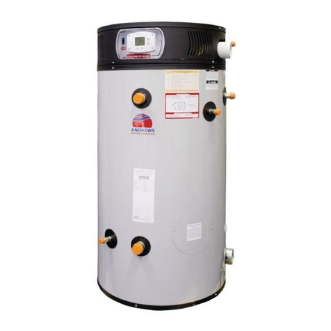
andrews ECOflo Series Installation and service manual

xFyre
xFyre 300A Installation & operating instructions
GSW
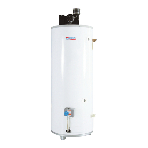
GSW Superflue Installation and operating instructions

BLADES LCS
BLADES LCS BLADE TWIN PLUS TPWH60 Installation & service manual

State Water Heaters
State Water Heaters GS6 40 YBVIT, GS6 40 HBVIT, GS6 50 YBVIT, GS6 50 HBVIT, GS6 40 YBVIT 2, GS6 40 HBVIT 2, GS6 50 YBVIT 2, GS6 50 HBVIT... Specifications
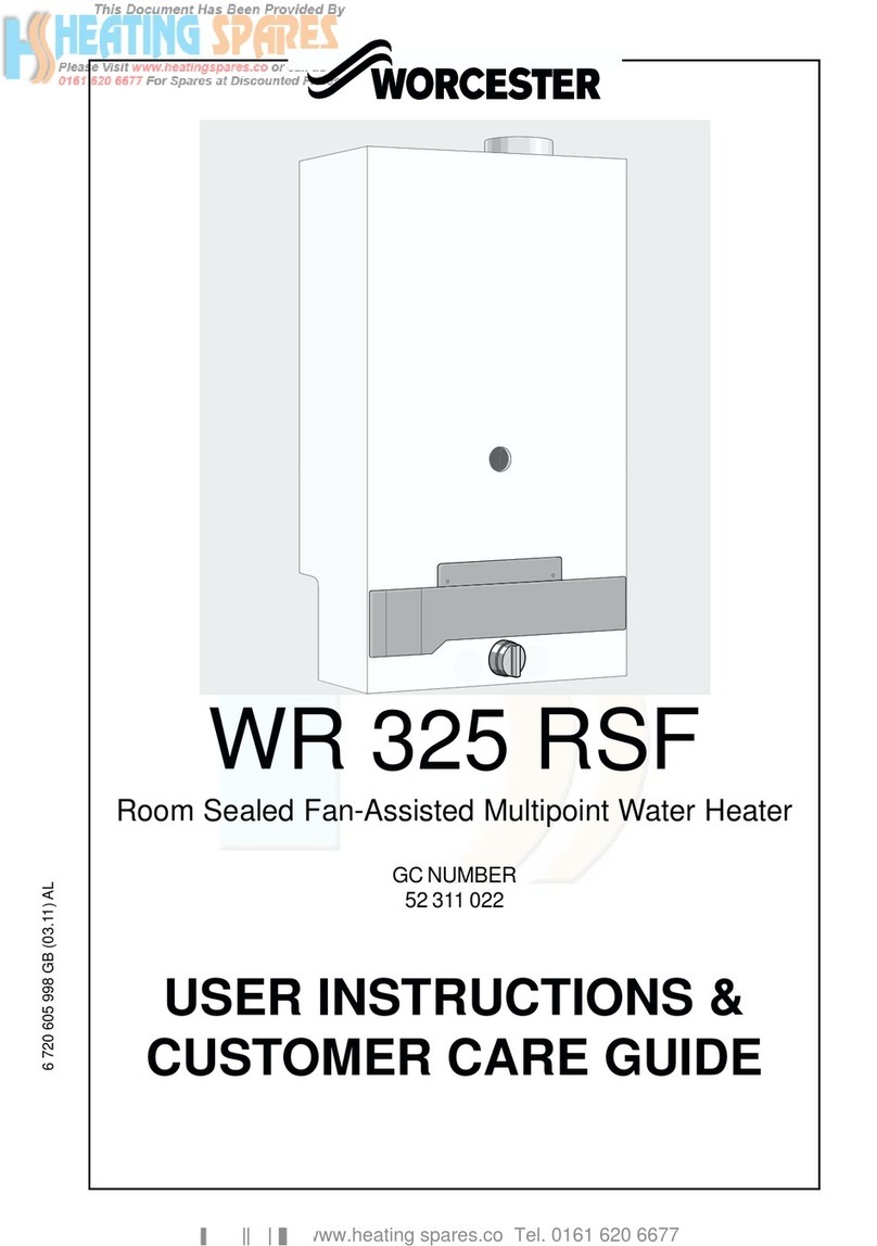
Worcester
Worcester WR 325 RSF User instructions & customer care guide

STIEBEL ELTRON
STIEBEL ELTRON DHE?18 SLi 25 A Operating and installation instructions
Technotherm
Technotherm CDE 18-27 VarioSelect Installation and technical manual

Siemens
Siemens DH 12400DH 12401DH 18400 installation instructions

Vaillant
Vaillant ecoFIT pure 825 Installation and maintenance instructions
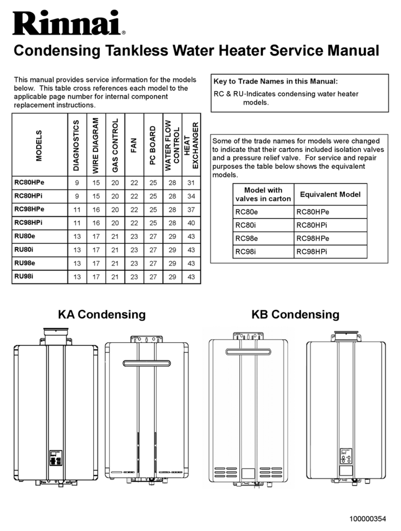
Rinnai
Rinnai REU-KA2530FFUD-US Service manual
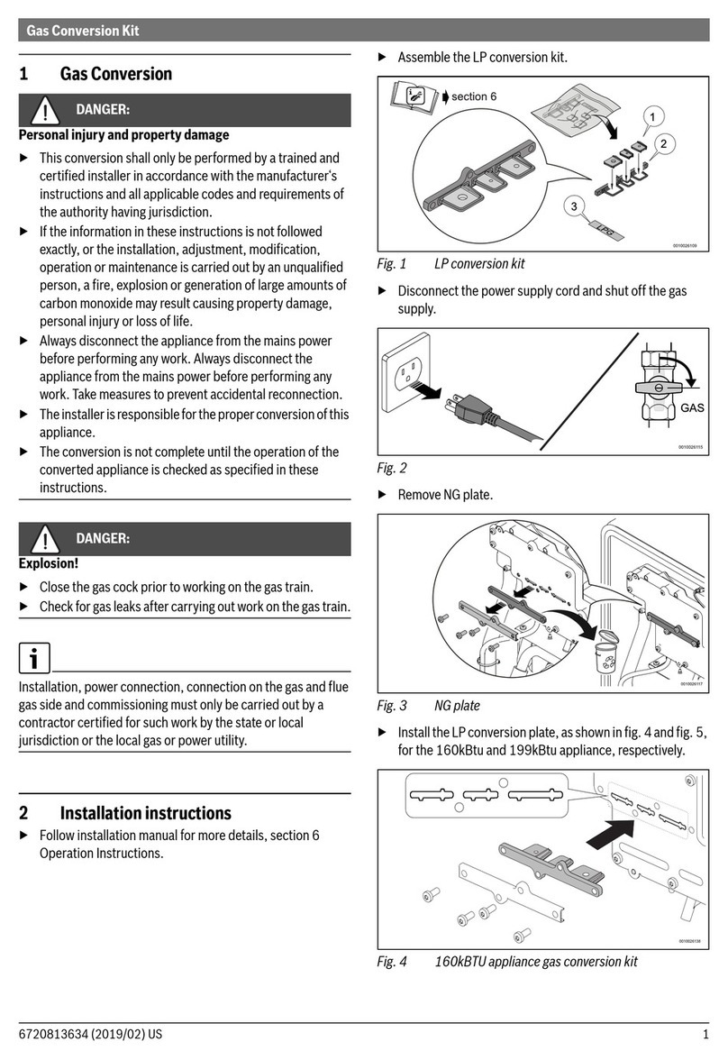
Bosch
Bosch Greentherm 9000 manual
A.O. Smith
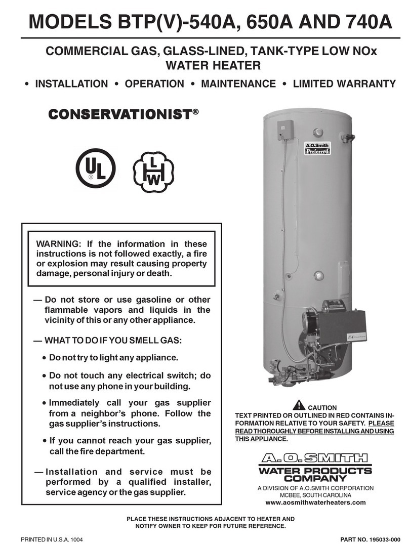
A.O. Smith Conservationist BTPV 650A Installation & operation

Amtrol
Amtrol EXTROL EX Series Installation & operation instructions
Edesa
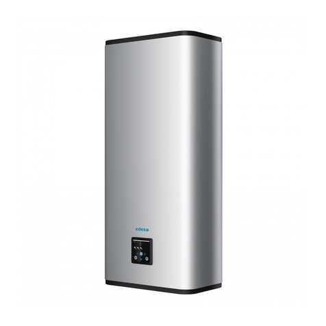
Edesa Flat Assembly, Use, Maintenance Manual

A.O. Smith
A.O. Smith BTI - 100 Specifications

American Water Heater
American Water Heater BCL380T1996NOX instruction manual

Timberk
Timberk T-WSS30-N28-V instruction manual


