Heiko JZ035-C2 User manual

SERVICE MANUAL
Outdoor unit
This service information is designed for experienced repair technicians only and is not designed for use by the general public.
It does not contain warnings or cautions to advise non-technical individuals of potential dangers in attempting to service a product.
Products powered by electricity should be serviced or repaired only by experienced professional technicians. Any attempt to service or
Repair the product or products dealt with in this service information by anyone else could result in serious injury or death
WARNING
Version :V1 Date:20 61-21-02
Model No: JZ035-C2

Contents
Domestic air conditioner
Contents
1. Introduction ............................................................................................1
2. Specifications.........................................................................................7
3. Sensors list ............................................................................................8
4. Piping diagrams .....................................................................................9
5. Operation range....................................................................................10
6. Printed circuit board connector wiring diagram ....................................11
7. Functions and control..............................................................................
8. Dimensional drawings...........................................................................
9. Center of gravity ...................................................................................
10. Service diagnosis ...............................................................................
11. Performance and curves diagrams.....................................................
12. Circuit diagrams..................................................................................
15
48
30
29
29
56

Introduction
Domestic air conditioner
1. Introduction
1
1.1 Safet y Cautions
Be sure to read the following safety cautions before condu cting repair work.
The caution it ems are classified int o “ Warning” and “C aut ion”. The “ Warning” items are especially important
since they can lead to deat h or serious injury if they are not followed closely. The “C aution” it ems can also
lead to serious accidents unde r some cond it ions if they are not followed. Therefore, be sure to observe all the
safety
caution items described below.
●
About t he pictograms
△This symbol indicates an it em for which caution must be exercised.
The pictogram shows the item to which att ention must be paid.
○This sym bol indicates a prohibited action.
The prohibited item or action is shown inside or near the symbol.
●This sym bol indicates an action that must be taken, or an instruction.
●
The instruction is shown inside or near the symbol.
Aft er the repair work is complete, be sure to condu ct a test operation to ensure that t he equipm ent operates
●
Norm ally, and explain the caut ions for operating the produ ct t o t he customer.

Introduction
2 Domestic air cond itioner
1.2.1 Embedded wire checking before installation
Check the embedded wire diameter suitable to request:
(Power supp ly from indoo r: 2.5kw ≥1.0mm2
3.5kw,5kw ≥1.5mm2 7kw ≥2.5mm2; Power supp ly from outdoor
≥1 .0mm2
)
Check the embedded wire are four roots, L/N/COM/GND; GND is needed, if not, thunde r or high voltage wave
from power grid will impact to the performance
Using a multi-meter to test short circuit of the four roots wires, make sure no short circuit happen .
1.2.2 Caution in Repair
Warning
Be sure to disconn ect the power cable plug from the plug socket
●
before disassembling the equipm ent for
a repair.
Working on t he equipment that is connected to a power supply can cause an electrical shook.
If it is necessary to supp ly power to the equipm ent to condu ct the repair or inspecting the circuits, do not
touchany electrically charged sections of t he equipment.

Introduction
3 Domestic air conditioner
If the refrigerant gas discharges during the repair work, do not touch the discharging refrigerant gas .The
refrigerant gas can cause frostbite.
When disconnecting the suction or discharge pipe of the compressor at the welded section, release the
refrigerant gas completely at a well-ventilated place first.
If there is a gas remaining inside the compressor , the refrigerant gas or
●cooling machine oil discharges
when the pipe is disconnected, and it can cause injury.
If the refrigerant gas leaks during the repair work, ventilate the area. The refrigerant gas can generate
●
toxic gases when it contacts flames.
●
The step-up capacitor supplies high-voltage electricity to the electrical components of the outdoor unit.
Be sure to discharge the capacitor completely before conducting repair work . A charged capacitor can
●
cause an electrical shock.
Do not start or stop the air conditioner operation by plugging or unplugging the power cable plug.
Plugging or unplugging the power cable plug to operate the equipment can cause an electrical shock or
fire.
Warning
Do not repair the electrical components with wet hands . Working on the equipment with wet hands can
●
cause an electrical shock
Do not clean the air conditioner by splashing water. Washing the unit with water can cause an electrical
shock.
Be sure to provide the grounding when repairing the equipment in a humid or wet place, to avoid
electrical shock.
Be sure to turn off the power switch and unplug the power cable when cleaning the equipment. The
internal fan rotates at a high speed, and cause injury.
Do not tilt the unit when removing it. The water inside the unit can spill and wet the furniture and floor.
Be sure to check that the cooling cycle section has cooled down sufficiently before conducting repair
work. Working on the unit when the cooling cycle section is hot can cause burns.
Use the welder in a well-ventilated place. Using the welder in an enclosed room can cause oxygen
deficiency.

Introduction
4 Domestic air conditioner
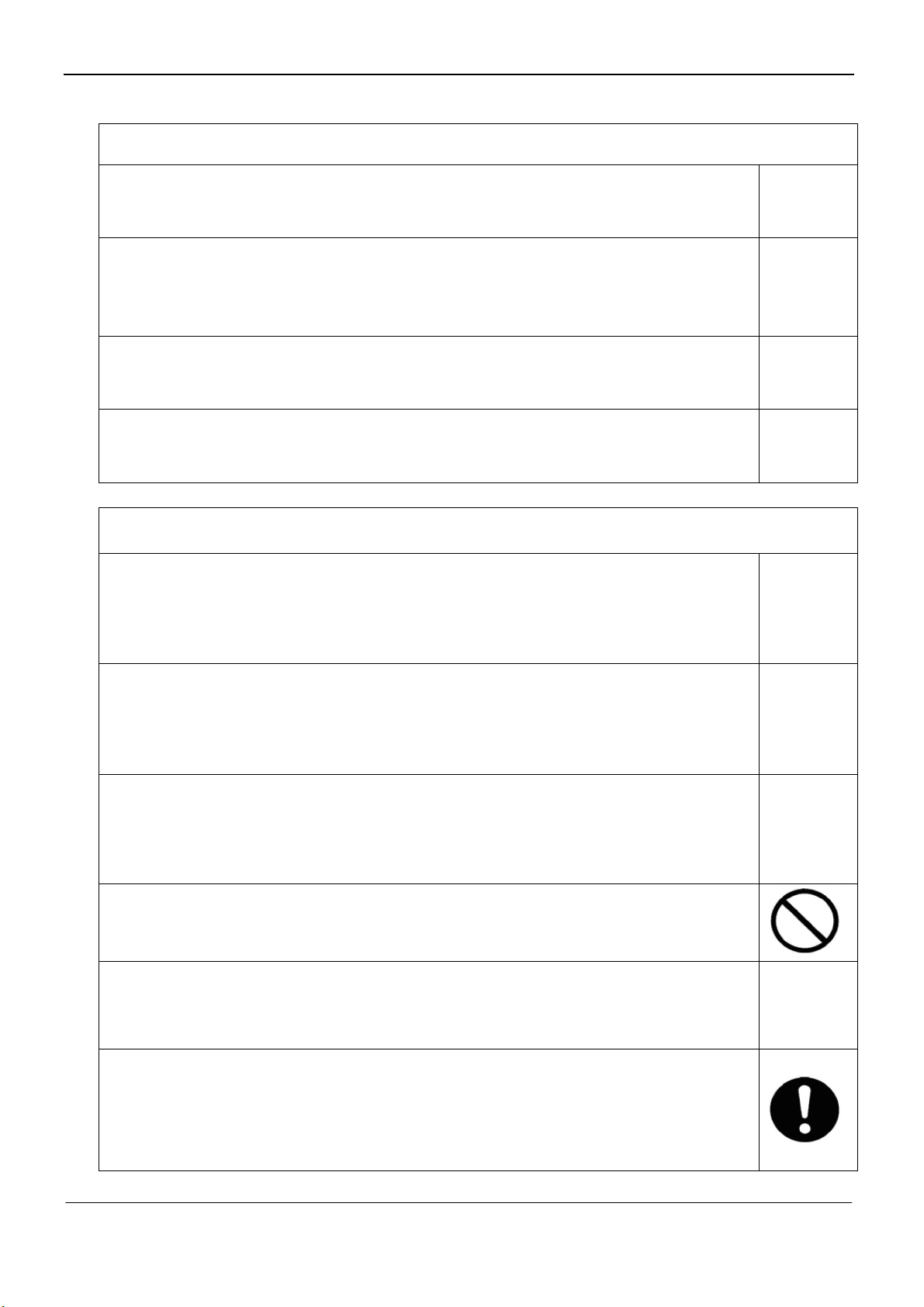
1.2.3 Cautions Regarding Products after Repair
Warning
Be sure to use parts listed in the service parts list of the applicable model and appropriate tools to
conduct repair work. Never attempt to modify the equipment. The use of inappropriate parts or tools can
cause an electrical shock, excessive heat generation or fire.
When relocating the equipment, make sure that the new installation site has sufficient strength to
withstand the weight of the equipment.
If the installation site does not have sufficient strength and if the installation work is not conducted
securely, the equipment can fall and cause injury.
Be sure to install the product correctly by using the provided standard installation frame.
Incorrect use of the installation frame and improper installation can cause the equipment to fall, resulting
in injury.
For
integral
units only
Be sure to install the product securely in the installation frame mounted on a window frame.
If the unit is not securely mounted, it can fall and cause injury.
For
integral
units only
Warning
Be sure to use an exclusive power circuit for the equipment, and follow the technical standards related to
the electrical equipment, the internal wiring regulations and the instruction manual for installation when
conducting electrical work.
Insufficient power circuit capacity and improper electrical work can cause an electrical shock or fire.
Be sure to use the specified cable to connect between the indoor and outdoor units. Make the
connections securely and route the cable properly so that there is no force pulling the cable at the
connection terminals.
Improper connections can cause excessive heat generation or fire.
When connecting the cable between the indoor and outdoor units, make sure that the terminal cover
does not lift off or dismount because of the cable.
If the cover is not mounted properly, the terminal connection section can cause an electrical shock,
excessive heat generation or fire.
Do not damage or modify the power cable.
Damaged or modified power cable can cause an electrical shock or fire. Placing heavy items on the
power cable, and heating or pulling the power cable can damage the cable.
Do not mix air or gas other than the specified refrigerant (R-410A / R22) in the refrigerant system.
If air enters the cooling system, an excessively high pressure results, causing equipment damage
and injury.
If the refrigerant gas leaks, be sure to locate the leak and repair it before charging the refrigerant. After
charging refrigerant, make sure that there is no refrigerant leak.
If the leak cannot be located and the repair work must be stopped, be sure to perform pump- down and
close the service valve, to prevent the refrigerant gas from leaking into the room. The refrigerant gas
itself is harmless, but it can generate toxic gases when it contacts flames, such as fan and other heaters,
.

Introduction
5 Domestic air conditioner
stoves and ranges.
When replacing the coin battery in the remote controller, be sure to disposed of the old battery to prevent
children from swallowing it.
If a child swallows the coin battery, see a doctor immediately.
Caution
Installation of a leakage breaker is necessary in some cases depending on the conditions of the
●
installation site, to prevent electrical shocks.
Do not install the equipment in a place where there is a possibility of combustible gas leaks.
If a combustible gas leaks and remains around the unit, it can cause a fire.
●
Be sure to install the packing and seal on the installation frame properly. If the packing and seal are not
installed properly, water can enter the room and wet the furniture and floor.
●
1.2.4 Inspection after Repair
Warning
Check to make sure that the power cable plug is not dirty or loose, then insert the plug into a power outlet
all the way.
If the plug has dust or loose connection, it can cause an electrical shock or fire.
If the power cable and lead wires have scratches or deteriorated, be sure to replace them.
Damaged cable and wires can cause an electrical shock, excessive heat
● generation or fire.
Warning
Do not use a joined power cable or extension cable, or share the same power outlet with other electrical
●
appliances since it can cause an electrical shock, excessive heat generation or fire.

Introduction
6 Domestic air conditioner
Caution
Check to see if the parts and wires are mounted and connected properly, and if the connections at the
soldered or crimped terminals are secure. Improper installation and connections can cause excessive
heat generation, fire or an electrical shock.
If the installation platform or frame has corroded, replace it. Corroded installation platform or frame can
●
cause the unit to fall, resulting in injury.
Check the grounding, and repair it if the equipment is not properly grounded. Improper grounding can
cause an electrical shock.
Be sure to measure the insulation resistance after the repair, and make sure that the resistance is 1 M
ohm or higher.
Faulty insulation can cause an electrical shock.
Be sure to check the drainage of the indoor unit after the
●repair.
Faulty drainage can cause the water to enter the room and wet the furniture and floor.
1.2.5 Using Icons
Icons are used to attract the attention of the reader to specific information. The meaning of each icon is described in
●
the table below:
1.2.6 Using Icons List
Icon Type of Information Description
Note Note A “note” provides information that is not indispensable, but may
nevertheless be valuable to the reader, such as tips and tricks.
Caution Caution
A “caution” is used when there is danger that the reader, through
incorrect manipulation, may damage equipment, loose data, get
an
unexpected result or has to restart (part of) a procedure.
●
Warning Warning A “warning” is used when there is danger of personal injury.
Reference
●
A “reference” guides the reader to other places in this binder or in
this manual, where he/she will find additional information on a
specific topic.

Specification
Domestic air conditioner
7
2 .Specifications
NOMINAL DISTRIBUTION SYSTEM VOLTAGE
1/esahP
05zHycneuqerF
0-24022VegatloV
NOMINAL CAPACITY and NOMINAL INPUT
cooling heating
Capacity rated KW
3.2(0.8-3.6)
Btu/h
Power Consumption(Rated) KW 1.07 1.0
0.41.6W/WPOCS/REES
184hWKnoitpmusnocygrenelaunnA
h/³mlavomeRerutsioM
TECHNICAL SPECIFICATIONS-UNIT
Dimensions H*W*D mm 700×245×544
Packaged
Dimensions H*W*D mm 845×320×593
23.5GK/thgieW
GK/thgiewssorG
Sound level 51erusserpdnuoS
64BdrewopdnuoS
ELECTRICAL SPECIFICATIONS
gnitaehgnilooc
4.58.4AtnerrucgninnurlanimoN
Maximum running current A 7.1 7.1
4.14.1AtnerrucgnitratS
TECHNICAL SPECIFICATIONS-PARTS
gnitaehgnilooc
Compressor
rosserpmoCyratoRepyT
GSD102RKQA6JT6BledoM
099WtuptuorotoM
tnelaviuqero
ACS-68R
epytliO
23.0LemulovegrahcliO
Fan
naflaixAepyT
04WtuptuorotoM
.2100h/³m)hgih(etarwolfriA
850/300mpr)wol/hgih(deepS
Heat
exchanger
Type ML fin- 7
.HI-HX tube
4.1*21*1hctif*egats*woR
1.4*10 ³
980
50
63
dB(A)
(A)
3.4
(0.8-4.2)
10920(2730-12286)11603(2730-14330)
26

Specification
Domestic air conditioner
8
TECHNICAL SPECIFICATIONS-OTHERS
Refrigerant
circuit
Refrigerant type R32
Refrigerant charge KG 0.53
Maximum allowable distance
between indoor an outdoor m 20
Maximum allowable level difference m 10
Refrigerant control
Piping connections
(external diameter)
liquid mm 6.35
gas mm 9.52
drain mm 16
Heat insulation type Both liquid and Gas pipes
Max. piping Length m 20
Max. vertical Difference m 10
Chargeless m 5
Amount of Additional Charge of Refrigerant g/m 20
Intemational Protection degree IP X4
Note: the data are based on the conditions shown in the table below
htgnelgnipiPgnitaehgnilooc
Indoor: 27 DB/19 WB
Outdoor: 35 DB/24 WB
Indoor:20 DB
Outdoor: 7 DB/6 WB 5m
3 Sensors list
type Description Qty
Ambient sensor Its used for detecti edisroodtuofoerutarepmetgn
Defrosting sensor Its used for controlling outdoor defrosting at heating mode 1
taeh-revofoesacnirosserpmocrofdesustIrosnesgnigrahcsiD
Conversation formulae
Kcal/h= KW×860
Btu/h= KW×3414
cfm=m³/min×35.3
CAPILLARY

Piping diagrams
Domestic air conditioner
4ˊPiping diagrams
9

Operation range
10 Domestic air conditioner
5.Operation range
-10
0
21
27
35
20
40
60
43
-20
-40

11 Domestic air conditioner
Printed circuit board connector wiring diagram
6. Printed circuit board connector wiring diagram
PCB (Control PCB)
UNIT MODEL PCB MODEL
JZ035-C2 0011801048A
1 CN1 Connector for power N and L
2 CN2
3 CN3
Connector for ground
4
CN
7 Connector for the U, V, W wire of the compressor
5 CN8
6 CN9
7 L-IN (CN5) Connector for reactor
8 L-OUT (CN6)
9 CN10 Connector for fan motor
10 CN11 Connector for four way valve coil
11 CN15 Connector for Temperature sensor
12 CN12 Connector for HEATER
13 CN4 Connector for communicate between indoor and outdoor unit
14 CN16 Connector for electric expansion valves
CN4
CN12
CN11
CN15
CN16
CN1
CN10
CN7/CN8/CN9
CN5
CN3
CN2
CN6

Functions and control
13 Domestic air conditioner
Wiring diagrams
OUTDOOR UNIT

Functions and control
15 Domestic air conditioner
7. Functions and control
7.1 Main functions and control specification
7.1.1 The operation frequency of outdoor unit and its control
7.1.1.1 The operation frequency control of compressor
The operation frequency scope of compressor
Mode Minimum operation frequency Maximum operation frequency
Heating 09K 30Hz 75Hz
Refrigeration 09K
7.1.1.2 The starting of compressor
When the compressor is started for the first time, it must be kept under the conditions of
38Hz,58Hz,88Hz for 30second,one minute, one minute (the overheating protection of the outdoor unit
air-blowing temperature, immediately decrease the frequency when the compressor is overflowing and
releasing the pressure) then it can be operated towards the target frequency. When the machine runs
normally, there’s no such process. After starting the compressor for operation, the compressor should
run according to the calculated frequency, and every determined frequency for protection should be
prior to the calculated frequency.
7.1.1.3 The speeds of increasing or decreasing the frequency of the compressor
The speed of increasing or decreasing the frequency rapidly 1 -----------1HZ/second
The speed of increasing or decreasing the frequency slowly 2 -----------1HZ/10seconds
7.1.1.4 The calculation of the compressor’s frequency
Refrigeration/dehumidification mode:
Pn=(Nh_c- S_c)*10 50 outdoor environment control
Pn=(Nh_c- S_c) *10 50 PID control
Heating mode:
Pn=(S_c -Nh_c) *10 60 outdoor environment control
Pn=(S_c -Nh_c) *10 60 PID control
(Nh_c=indoor environment temperature S_c=setting temperature)
1The minimum/maximum frequency limitation
AWhile refrigerating: F-MAX-r is the maximum operation frequency of the compressor; F-MIN-r is the
minimum operation frequency of the compressor.
BWhile heating: F-MAX-d is the maximum operation frequency of the compressor; F-MIN-d is the
minimum operation frequency of the compressor.
2The frequency limitation which is affected by the environment temperature.
(Wh_c= environment temperature)
Heating mode:
Serial No. Temperature scope Frequency limitation 09K
1 Wh_c<-12 Max_hz1 99HZ
2 Wh_c<-8 Max_hz2 99HZ
30Hz 99 Hz

Functions and control
16 Domestic air conditioner
3 Wh_c<-2 Max_hz3 99HZ
4 Wh_c<5 Max_hz4 93HZ
5 Wh_c<10 Max_hz5 82HZ
6 Wh_c<17 Max_hz6 66HZ
7 Wh_c<20 Max_hz7 59HZ
8Wh_c> 20 Max_hz8 51HZ
Remarks: The above are the maximum frequency limitations of the complete appliance which are
affected by the environment, and they have nothing to do with the ability of the indoor unit.
Refrigeration/dehumidification mode:
Serial No. Temperature scope Frequency limitation 09K
1 Wh_c<16 Max_hz1 44HZ
2 Wh_c<22 Max_hz2 49HZ
3 Wh_c<29 Max_hz3 56HZ
4 Wh_c<32 Max_hz4 63HZ
5 Wh_c<40 Max_hz5 75HZ
6 Wh_c<48 Max_hz6 55HZ
7 Wh_c>=48 Max_hz7 39HZ
Remarks: the above are not only the maximum frequency limitations of the complete appliance
which are affected by the environment, but also the maximum ability limitation of the system. When the
starting ability is not the maximum, its maximum frequency limitation is calculated by the following
equations:
The frequency limitation which is affected by the temperature and under the condition of actual
ability the actual running system ability*the maximum frequency which is limited by the temperature
and under the condition of maximum ability/the maximum designing ability of the system
Refrigeration/dehumidification mode:
Heating mode:
The calculation of the actual output frequency:
F= F-ED-*(rated frequency) K
F-ED-*(rated frequency)= The frequency which is limited by the outdoor environment temperature
Notes:
When refrigerating, it is needed to satisfy
The indoor setting
airflow speed Low Medium Quiet
The percentage of the
rated frequency K
(09K)
70% 85% 42%
The indoor setting
airflow speed Low Medium Quiet
The percentage of the
rated frequency K
(09K)
80% 90% 50%

Functions and control
17 Domestic air conditioner
F-MIN-d(compressor’s Min_hz)< F<F-MAX-d(compressor’s Max_hz)
When heating, it is needed to satisfy
F-MIN-r (compressor’s Min_hz)< F<F-MAX-r (compressor’s Max_hz)
PID control :
The innital frequency Sn is determined by Pn . We can calculate Hzoutf according to the value of Kp ,Ki ,Kd,
Out_gain,Pn.Then , Fn = Sn + Hzoutf. The value of Fn is calculated in each sample time (60 seconds),and Fn is
adujusted according to previous frequency of Sn and filtered output of Hzoutf.
7.1.2 The outdoor fan control (Exchange fan)
When the fan is changed among every airflow speed (including stop blowing), in order to avoid the
airflow speed from skipping frequently, it must be kept under each mode for over 30 seconds, and then
it can be changed to another mode (when refrigerating, the time is changed to 15 seconds).
7.1.2.1 The outdoor fan control
Within three minutes of compressor starting, the compressor is controled according to the ambient temperature.
Tao Tao <22 22 < Tao <28 Tao 28
Refrigeration/dehumidification
(09K)
3rd level 5th level 7th level
Tao Tao <<10 10 < Tao <17 Tao 17
Heating level level 3rd level
After 3 minutes, the compressor is controled according to the ambient temperature and the frequency of the
compressor.
Refrigeration/dehumidification
frequency Hz 09K
<40 Hz 40 Hz -55 Hz 55 Hz
Tao
22 2nd level 3rd level 5 th level
22-28 3rd level 5 th level 7 th level
28 7 th level
Heating frequency Hz
(09K) <51 Hz 51-71 Hz 71 Hz
Tao
10 5th level 7th level 7th level
10-17 3rd level 4 th level 5th level
17 2nd level
7th
5th

Functions and control
18 Domestic air conditioner
7.1.4 Four way control
For the details of defrosting four-way valve control, see the defrosting process.
Four way working in other ways:
Under the mode of heating, open the four-way valve, when the compressor is not started or
changed to non-heating mode, make sure the compressor is stoped for 2 minutes, and then close the
four-way valve.
7.1.5 Protection function
7.1.5.1 TTC high temperature-preventing protection
Once the machine is started, it can run TTC(air-blowing temp) overheating protection of
air-blowing, but air-blowing sensor malfunction must alarm after 4 minutes during which the
compressor is started (during the course of self-detection, there’s no such limitation)
Sensor detection methods: 100 times (one cycle of procedure run is one time, and about 5ms,
detection method for each time: continuously sampling for 8 times, then order them and take the mean
value of the middle 2 values), take the mean value.
TTC
09K Abnormal stop
107
Decreasing the frequency rapidly 1HZ/second
102
Decreasing the frequency slowly (1HZ/10seconds)
98
The frequency doesn’t change.
95
Increasing the frequency (1HZ/10second)
93
Increasing the frequency 1HZ/1second
TTC>=110 lasts for 20 seconds. Overheating protection of air-blowing, alarm malfunction to the
indoor, others don’t last.
7.1.5.2 TC high temperature-preventing control of the indoor heating unit
Tpg_indoor is the highest value of the effective indoor unit (start it and it is in accord with the
running state). TC=indoor coil temp.
The indoor heat exchanger sensor tests the temperature of the indoor heat exchanger. If the
temperature is higher than 63 , decrease the rotate speed of the compressor and do the high
temperature-preventing protection of the indoor heat exchanger; if the temperature of the indoor heat
exchanger is lower than 45 , recover to the normal control.

Functions and control
19 Domestic air conditioner
(09K)
TC( ) The compressor stops Fgh_t1 63
Fgh_t1 2
Fgh_t2 2 N Decreasing the frequency rapidly Fgh_t2 60
P Decreasing the frequency slowly Fgh_t3 57
Fgh_t3 2
Fgh_t4—2 Q Prohibiting increasing the frequency Fgh_t4 52
R Increasing slowly Fgh_t5 40
Fgh_t5—2
Normal
NDecreasing at the speed of 1HZ/1 second
P Decreasing at the speed of 1Hz/10 seconds
Q Continue to keep the last-time instruction cycle
R Increasing at the speed of 1Hz/10seconds
Remarks: the outdoor unit
7.1.5.3 The control of preventing the over current of the compressor:
During the starting process of the compressor, if the current of the compressor is greater than 12.5A
for 3 seconds, stop the compressor and alarm, after 3 minutes, start it again, if such state appears 3
times in 20 minutes, stop the compressor and alarm, and confirm the malfunction. Then continue to
run it only after the power is off.
During the starting process of the compressor, if the AC current is greater than 9A, the frequency of
the compressor decreases at the speed of 1HZ/second.
During the starting process of the compressor, if the AC current is greater than 8A, the frequency of
the compressor decreases at the speed of 0.1HZ/second.
During the starting process of the compressor, if the AC current is greater than 7.5A, the frequency
of the compressor increases at the prohibited speed.
During the starting process of the compressor, if the AC current is greater than 6.5A, the frequency
of the compressor increases at the speed of no faster than 0.1HZ/second.
7.1.5.4 The protection function of AC current:
During the starting process of the compressor, if the AC current is greater than 12.5A for 3 seconds,
stop the compressor and alarm, after 3 minutes, start it again, if such state appears 3 times in 20
minutes, stop the compressor and alarm, and confirm the malfunction. Then continue to run it only
after the the power is off.
During the starting process of the compressor, if the AC current is greater than 9A, the frequency of
the compressor decreases at the speed of 1HZ/second.
During the starting process of the compressor, if the AC current is greater than 8A, the frequency of

Functions and control
20 Domestic air conditioner
the compressor decreases at the speed of 0.1HZ/second.
During the starting process of the compressor, if the AC current is greater than 7.5A, the frequency of
the compressor increases at the prohibited speed.
During the starting process of the compressor, if the AC current is greater than 6.5A, the frequency of
the compressor increases at the speed of no faster than 0.1HZ/second.
Remarks: when the outdoor temperature is high, there’s compensation for AC current protection.
(1) When the outdoor environment temperature is higher than 40ć, AC current protection value
decreases by 2A/1A(09K/12K).
(2) When the outdoor environment temperature is higher than 50ć, AC current protection value
decreases by 3A/2A(09K/12K).
7.1.5.5 Anti-freezing protection of the indoor heat exchanger
When refrigerating/heating, prevent freezing.
Tpg_indoor is the minimum value of the effective indoor unit (start it and it is in accord with the running
state).
11ć//ice_temp_3+5
ice_temp_3+3 9ć
Increasingslowly
8ć//ice_temp_3+2
Keeping the frequency
ice_temp_3 7ć7ć
ice_temp_2 5ćDecreasingslowly
ice_temp_1 3ćDecreasing rapidly ice_temp_1
1ćStop
When Tpg_indoorLJice_temp_1, the frequency of the compressor decreases at the speed of
1HZ/1second.
When Tpg_indoorLJice_temp_2, the frequency of the compressor decreases at the speed of
1HZ/10seconds.
When Tpg_indoor begins to rise again, and ice_temp_2İTpg_indoorİice_temp_3, the frequency
of the compressor doesn’t change.
When ice_temp_3LJTpg_indoorLJice_temp_3+3ć, the frequency of the compressor increases at the
speed of 1HZ/10seconds.
For example, Tpg_indoorİ0ćˈlast for 2 minutes, and then the outdoor unit will stop, and report
underload malfunction, but don’t send malfunction report to the indoor.
The compressor stops for more than 3 minutes, Tpg_indoor> ice_temp_3+2ć, the compressor
recovers.
7.1.5.6 The frequency limitation of modification rate
In the field which is controlled by high frequency, if the modification rate is not high enough, the
control-driven chip will enter into weak magnetic control, this will help to relieve the problem of
Table of contents
Other Heiko Air Conditioner manuals

Heiko
Heiko JZ025-C2 User manual

Heiko
Heiko JS025-QW2 User manual

Heiko
Heiko JZ050-Q2 User manual

Heiko
Heiko JS026-B1 User manual

Heiko
Heiko JZ050-C2 User manual

Heiko
Heiko JZ070-A1 User manual

Heiko
Heiko JS050-QW2 User manual

Heiko
Heiko T Series User manual

Heiko
Heiko CA035-A1 Installation and operating instructions

Heiko
Heiko JS035-C2 User manual

Heiko
Heiko 2P Series User manual

Heiko
Heiko JS026-D1 User manual

Heiko
Heiko JS035-QW2 User manual

Heiko
Heiko T Series User manual

Heiko
Heiko JZ025-Q2 User manual

Heiko
Heiko JZ100-A1 User manual

Heiko
Heiko JS070-C2 User manual

Heiko
Heiko JZ070-A1 User manual

Heiko
Heiko JZ035-A2 User manual

Heiko
Heiko JS068-C2 User manual