HEKA PG 310 User manual

Manual 1.0
PG 310/PG 390
PG 340
Potentiostat / Galvanostat

HEKA Elektronik Phone +49 (0) 6325 / 95 53-0
Dr. Schulze GmbH Fax +49 (0) 6325 / 95 53-50
Wiesenstrasse 71 Web Site http://www.heka.com
D-67466 Lambrecht/Pfalz Email sales@heka.com
Germany support@heka.com
HEKA Electronics Inc. Phone +1 902 624 0606
47 Keddy Bridge Road Fax +1 902 624 0310
R.R. #2 Web Site http://www.heka.com
Mahone Bay, NS B0J 2E0 Email nasales@heka.com
Canada support@heka.com
HEKA Instruments Inc. Phone +1 516 882-1155
2128 Bellmore Avenue Fax +1 516 467-3125
Bellmore, New York Web Site http://www.heka.com
11710-5606 U.S.A. Email ussales@heka.com
support@heka.com
Title Page: Potentiostat/Galvanostat PG 310
©
2004-2008 HEKA Elektronik Dr. Schulze GmbH
COMDP9/1

Contents
1 Introduction 1
1.1 Introducing the PG 310, PG 390, and PG 340 . . . . . . . . 1
1.2 Naming Conventions . . . . . . . . . . . . . . . . . . . . . . 2
1.3 Product Intended Usage . . . . . . . . . . . . . . . . . . . . 3
1.4 Supplied Components . . . . . . . . . . . . . . . . . . . . . 3
1.5 Unpacking . . . . . . . . . . . . . . . . . . . . . . . . . . . . 4
1.6 Computer Requirements . . . . . . . . . . . . . . . . . . . . 4
1.6.1 Windows . . . . . . . . . . . . . . . . . . . . . . . . 4
1.6.2 Macintosh . . . . . . . . . . . . . . . . . . . . . . . . 4
1.7 Support Hotline . . . . . . . . . . . . . . . . . . . . . . . . . 5
2 Description of the Hardware 7
2.1 Characteristics . . . . . . . . . . . . . . . . . . . . . . . . . 7
2.1.1 Power Requirements . . . . . . . . . . . . . . . . . . 7
2.1.2 Dimensions . . . . . . . . . . . . . . . . . . . . . . . 7
2.1.3 True Plug-and-Play . . . . . . . . . . . . . . . . . . 7
2.1.4 Hot-Swappable . . . . . . . . . . . . . . . . . . . . . 8
2.1.5 Expandability . . . . . . . . . . . . . . . . . . . . . . 8
2.1.6 DC Characteristics . . . . . . . . . . . . . . . . . . . 8
2.1.7 Potentiostatic Mode . . . . . . . . . . . . . . . . . . 9
2.1.8 Galvanostatic Mode . . . . . . . . . . . . . . . . . . 9

ii CONTENTS
2.1.9 Dynamic Data . . . . . . . . . . . . . . . . . . . . . 9
2.1.10 Initial Potential . . . . . . . . . . . . . . . . . . . . . 10
2.1.11 Polarity Convention . . . . . . . . . . . . . . . . . . 10
2.2 Main Unit . . . . . . . . . . . . . . . . . . . . . . . . . . . . 11
2.2.1 Rear Panel . . . . . . . . . . . . . . . . . . . . . . . 11
2.2.2 Front Panel . . . . . . . . . . . . . . . . . . . . . . . 11
2.3 Simplified Block Diagram . . . . . . . . . . . . . . . . . . . 15
3 Installation 17
3.1 Connecting the PG 300 . . . . . . . . . . . . . . . . . . . . 17
4 The Control Software 19
4.1 Controlling the PG 310/390 - Main Functions . . . . . . . . 20
4.1.1 Cell Connection . . . . . . . . . . . . . . . . . . . . 20
4.1.2 Potential / Current settings . . . . . . . . . . . . . . 21
4.1.3 Filter Settings . . . . . . . . . . . . . . . . . . . . . 23
4.1.4 Additional Settings . . . . . . . . . . . . . . . . . . . 26
4.1.5 Cell mode . . . . . . . . . . . . . . . . . . . . . . . . 27
4.1.6 Auto Range . . . . . . . . . . . . . . . . . . . . . . . 27
4.1.7 Macro Recording . . . . . . . . . . . . . . . . . . . . 28
4.2 Hidden Controls . . . . . . . . . . . . . . . . . . . . . . . . 30
4.2.1 Features for Macros . . . . . . . . . . . . . . . . . . 31
4.3 Controlling the PG 340 - Special Functions . . . . . . . . . 32
4.3.1 Electrode Conditions . . . . . . . . . . . . . . . . . . 33
4.3.2 Cell Connection . . . . . . . . . . . . . . . . . . . . 33
4.3.3 Potential/Current Settings . . . . . . . . . . . . . . 34
4.3.4 Additional Settings . . . . . . . . . . . . . . . . . . . 34
http://www.heka.com

CONTENTS iii
4.3.5 Cell Mode . . . . . . . . . . . . . . . . . . . . . . . . 34
5 Operating Modes 37
5.1 Potentiostatic Mode . . . . . . . . . . . . . . . . . . . . . . 38
5.1.1 Differential Amplifier . . . . . . . . . . . . . . . . . . 38
5.1.2 Current Amplifier . . . . . . . . . . . . . . . . . . . 39
5.1.3 Control Amplifier . . . . . . . . . . . . . . . . . . . . 39
5.2 Galvanostatic Mode . . . . . . . . . . . . . . . . . . . . . . 42
5.2.1 IR Compensation . . . . . . . . . . . . . . . . . . . . 43
6 Appendix I: Technical Data 45
6.1 PG 300 Series ......................... 45
6.1.1 Digital I/O Connector . . . . . . . . . . . . . . . . . 45
6.1.2 Digital In Connector . . . . . . . . . . . . . . . . . . 46
6.1.3 Digital Out Connector . . . . . . . . . . . . . . . . . 47
6.2 PG 300 USB Series ...................... 48
6.2.1 Digital I/O Connector . . . . . . . . . . . . . . . . . 48
6.2.2 Digital In Connector . . . . . . . . . . . . . . . . . . 49
6.2.3 Digital Out Connector . . . . . . . . . . . . . . . . . 49
http://www.heka.com


1. Introduction
1.1 Introducing the PG 310, PG 390, and
PG 340
The PG 300 series potentiostat/galvanostat feature state-of-the-art ampli-
fier technology. They include amplification ranges for large currents, new
hardware filters and an external preamplifier design (optional) to reduce
noise levels for small currents. The most significant advance is the complete
software controlled adjustment of the amplifier. This provides the tools
necessary to perform virtually every electrochemical experiment. This also
allows for the simplification and automation of experimental procedures
and gives enormous flexibility for future extensions. The instant automatic
versatile and easy-to-use macro features yield measurements of the high-
est quality, all while retaining the possibility of full manual control of the
amplifier. Therefore, this instrument fulfills the needs of testing industrial
electrodes and scientific research. The versatility of the amplifier and its
superb technical specifications make the PG 300 the instrument of choice
for all electrochemical experiments.
The integration of the PG 300 amplifier with the LIH 8+8 AD/DA interface
and the connected computer constitutes a further step in the minimization
of total recording noise. Complemented by the intrinsic low noise level of
the PG 300 itself with the low current preamplifier, this integrated system
effectively eliminates all interferences because it is fully decoupled by op-
tical isolation that in conventional systems often arise from ground loops.
Furthermore, the full digital control by a computer running our dedicated
software achieves a well-compensated measuring arrangement necessary for
a minimum of noise.
Automatic calibration and testing procedures implemented in the software
control of the PG 300 guarantees exact functioning of the amplifier at all
times. The user can easily run a calibration process whenever it might be

2 Introduction
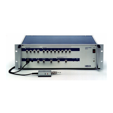
Figure 1.1: PG 340 USB Potentiostat / Galvanostat
necessary. The highly advanced integration of hardware and software of
the PG 300 system eliminates compatibility problems, time consuming set-
up operations, and training time. Furthermore, it saves the expenses for
additional instruments. The PG 300 controlled by the software Potmas-
ter and combined with a computer is equivalent to a fully equipped set-up
which includes a potentiostat/galvanostat, digital storage oscilloscope, vari-
able analog filter, sophisticated pulse generator, and a full featured data
acquisition and analysis system.
1.2 Naming Conventions
PG 310 USB, PG 390 USB, and PG 340 USB
Throughout the present manual we will address all three amplifier types as
“PG 300”. We will explicitly mention the particular amplifiers, where it is
required.
http://www.heka.com

1.3 Product Intended Usage 3
1.3 Product Intended Usage
The HEKA PG 300 is intended for research use only in a laboratory by
persons trained in its use. Users are expected to be able to properly operate
the PG 300 and associated instruments.
The HEKA PG 300 is not intended for medical use. The HEKA PG 300 is
not intended for use in life support situations, or in situations were improper
operation or failure of the PG 300 can result in personal injury.
HEKA makes no representation that the design, implementation, testing,
or manufacture of the PG 300 meet reasonable standards for use as a medi-
cal product. As stated in the HEKA Limited Warranty Statement, supplied
with each product, ”HEKA expressly disclaims all warranties to buyer ex-
cept the limited warranty set forth above, including without limitation to
any and all implied warranties of merchantability and fitness for a partic-
ular purpose.”
1.4 Supplied Components
The following items should have been packed with your PG 300:
1PG 300 potentiostat/galvanostst
1 USB 2.0 shielded cable (3 meters)
1 HEKA CD-ROM
1 Printed user’s manual
1 power cord (110 or 220 Volt depending on application)
If any of these items are missing please contact HEKA or your dealer im-
mediately.
http://www.heka.com

4 Introduction
1.5 Unpacking
After unpacking the PG 300 and accessories from the shipping carton,
please inspect each piece for any signs of shipping damage. Please con-
tact the delivering carrier and HEKA immediately if there is any damage.
Do not dispose of the shipping carton. The carrier will want to examine the
shipping carton to process a damage claim. HEKA insures all shipments
to cover shipping damage. It is also advisable to keep the shipping carton
in the event that the instrument must be returned for service.
1.6 Computer Requirements
1.6.1 Windows
Pentium 4 or faster processor
Windows 2000, XP or Vista
Available USB 2.0 Hi-Speed port (480 Mbits/second)
CD-ROM or internet access
1.6.2 Macintosh
Macintosh G5 or faster processor
Mac OS X (10.4 or higher)
Available USB 2.0 Hi-Speed port (480 Mbits/second)
CD-ROM or internet access
Please note that many newer computer systems are supplied with multi-
ple USB 2.0 ports, but only some of these ports are capable of Hi-Speed
operation. The PG 300 will work on the slower speed ports, but the maxi-
mum transfer rates will be greatly reduced. For optimal performance, the
PG 300 should only be connected to a USB 2.0 Hi-Speed port.
http://www.heka.com

1.7 Support Hotline 5
If your computer system does not have a Hi-Speed USB 2.0 port, then
a USB 2.0 adapter may be used. These adapters are available in many
configurations (PCI, PC Slot, etc).
1.7 Support Hotline
If you have any question, suggestion, or improvement, please contact
HEKA’s support team. The best way is to send us an e-mail or fax speci-
fying:
Your postal and E-mail address (or fax number)
The program name: Potmaster
The program version number: v2.30, v2.32
Your operating system and its version: MacOS 10.4, Windows XP
Prof., etc.
Your type of computer: Mac G5, Pentium 4, 1.8 GHz, etc.
Your acquisition hardware, if applicable: PG 310 USB, LIH 8+8
The series number and version of your potentiostat.
The questions, problems, or suggestions you have
Under which conditions and how often the problem occurs
We will address the problem as soon as possible.
HEKA Elektronik GmbH
Wiesenstrasse 71
D-67466 Lambrecht/Pfalz
Germany
phone: +49 (0) 6325 9553 0
fax: +49 (0) 6325 9553 50
e-mail: support@heka.com
web: http://www.heka.com
http://www.heka.com

6 Introduction
http://www.heka.com

2. Description of the Hardware
2.1 Characteristics
2.1.1 Power Requirements
AC-power 110 V or 220 V, 50 to 60 Hz,
170 W maximum (PG 310)
260 W maximum (PG 390)
2.1.2 Dimensions
Housing 43 cm W x 18 cm H x 35 cm D
(16.9” W x 7.1” H x 13.8” D)
Front panel 48,3 cm x 18 cm
(19” x 7.1”) with two handles
The PG 300model potentiostat/galvanostat can be mounted in a standard
19” rack assembly.
Weight 12.2 kg (27 lb)
2.1.3 True Plug-and-Play
Simply connect the PG 300 to an available Hi-Speed USB 2.0 port on the
host computer system using the supplied USB cable. The computer will
automatically identify the LIH 8+8 and install the appropriate driver soft-
ware, if needed, to operate it. This connection scheme greatly reduces
start-up time. It is no longer necessary to open the computer to add a
board. Simply make all of the connections to the recording setup and exe-
cute the data acquisition software. Within minutes, data can be acquired.

8 Description of the Hardware
2.1.4 Hot-Swappable
Another advantage of the USB based PG 300 data acquisition interface is
that it can be installed or removed while the computer is running. Just plug
the device in, use it, and unplug it when done. There is no need to power
down the computer. The PG 300 is self-enumerating and self-identifying.
The device driver is dynamically loaded when connected and dynamically
unloaded when unplugged.
2.1.5 Expandability
If an application requires more channels than are available on a single
PG 300, then multiple units can be connected and fully synchronized. Each
PG 300 unit requires a dedicated Hi-Speed USB 2.0 port and an external
cable connection between the units. This external connection is used to
synchronize the acquisition clocks of the units and is made with a standard
CAT5 patch cable. A single external trigger will start the multiple units
simultaneously. Please note that PG 300 interfaces installed on separate
computers can also be synchronized in the same manner. The number
of units that can be installed is only limited by the number of available
Hi-Speed USB 2.0 ports.
2.1.6 DC Characteristics
PG 310 PG 390
Counter Electrode:
Compliance Voltage ±20 V Compliance Voltage ±20 V
Output current ±2 A Output current ±1 A
Continuous Power:
20 W 90 W
Resolution current monitor: 0.02 % of full range
Resolution voltage monitor: 1 mV
Input specifications (reference electrode):
impedance: 100 GΩ in parallel with 1.5 pF
http://www.heka.com

2.1 Characteristics 9
2.1.7 Potentiostatic Mode
PG 310 PG 390
Counter electrode:
Potential range: ±20 V±90 V
2.1.8 Galvanostatic Mode
Current range ±1µA to ±2A(PG 590: ±1 A) in 8 (7) steps
Minimum resolution 0.02 %
2.1.9 Dynamic Data
Small signal rise time 0.1µs up to 200 µs maximum in 4 steps
controlled by a 3-pole Bessel filter
Slew rate 10 V/µs
Bandwidth >1 MHz in 1 mA-range at -3dB
Phase shift <10
°
at 200 kHz
2.1.9.1 Low Current Preamplifier
The input circuitry is contained in a hybrid integrated circuit (available
only for PG 310).
Current measuring resistors:
500 MΩ (1 nA; 100 pA)
5 MΩ (100 nA; 10 nA)
Noise measured with open input:
8-pole Bessel filter; 1 nA - 100 pA, 500 MΩ? feedback resistor:
DC to 10 kHz: ¡ 400 fA (RMS)
Maximum bandwidth: 100 kHz
2.1.9.2 Filters
The PG 310/PG 390 contains three built-in filters.
http://www.heka.com

10 Description of the Hardware
Voltage filter The voltage monitor can be filtered by a 3-pole Bessel filter
in three steps of 10, 100, or 1000 Hz.
Current filter The current monitor can be filtered by a 4-pole filter with
selectable Bessel or Butterworth characteristics from 0.5 to 16 kHz (Bessel)
or to 25 kHz (Butterworth).
Bandwidth control The power amplifier bandwidth can be controlled in 8
steps from 0.1 to 300 kHz.
2.1.10 Initial Potential
Total range of ±10 V can be set manually or through software control.
2.1.11 Polarity Convention
The PG 300 model potentiostats/galvanostats conforms to the polarity con-
vention that defines a cathodic current to be negative. That is a current
is negative if reduction is taking place. Positive current is anodic that is
a current is defined as positive if oxidation is taking place. The current
monitor and the monitor display are consistent with this convention.
In potentiostatic operation, applying a more positive potential will results
in a more anodic current. In contrast, a more negative potential applied
will results in a more cathodic current. This is also true for EXTERNAL
INPUT Stimulus voltages.
In the galvanostatic mode, applying a more positive current will tend to
cause a more anodic current. Conversely, a more negative applied current
will cause a more cathodic current. This sensing applies for any current
change regardless of its source. This includes the PG 300 EXTERNAL INPUT.
Note: The EXTERNAL INPUT has 5 KΩinput impedance in
both the potentiostatic and galvanostatic modes.
http://www.heka.com

2.2 Main Unit 11
2.2 Main Unit
The PG 300 main unit contains the analog main board with the analog scan
generator, the display board including two digital display modules and the
power-supply.
2.2.1 Rear Panel
Voltage Switch: A switch on the rear panel of the main unit selects
between the 110 and 220 volt operation. Make sure that the switch is in
the proper position, and that the correct fuse is installed.
Rear-panel connectors: Three 40-pin connectors and an analog trigger
input and output allow connection of the PG 300 to other devices:
USB: This is the connection to the host computer, that allows the com-
puter to communicate with the PG 300.
Digital I/O: TTL-level, digital input and output lines are available here
for the control and monitoring of digital signals.
Trigger In: Input for an external trigger to start data acquisition when
the LIH 8+8 is waiting for an external trigger. This mode is set in POT-
MASTER when either Trigger Series or Trigger Sweeps is selected in the
Pulse Generator.
PGate Out: Output for trigger signals. In common application this
output is not used.
2.2.2 Front Panel
Power Switch: In order to be initialized properly, the PG 300 should be
switched on before starting the POTMASTER program. However, this
program allows you to re-initialize the amplifier in case you forgot to turn
it on first.
Note: Since the calibration settings of the potentiostat have
been determined for a warmed-up potentiostat, switch on the
http://www.heka.com

12 Description of the Hardware
potentiostat ∼15 min before starting an experiment. This will
ensure that the potentiostat has warmed up to the regular work-
ing temperature and that the calibration parameters are most
accurate.
GND-CHAS: The chassis (CHAS) is connected to the ground line of the
power cord, as is typical of most instruments. The Signal ground (GND) is
kept separate from the chassis to avoid ground loops, but can be connected
to it through an external connector. To run the potentiostat with float-
ing ground, remove the external connector. Both with floating and with
chassis ground, the signal ground can be connected to other parts of the
experimental setup if necessary. In the first case, the banana jack of Signal
ground provides a high-quality connection to the other parts. In the latter
case the banana jack in the external connector must be used.
DA and AD connectors: The BNC connectors to the built-in laboratory
interface (LIH 8+8) are grouped into Digital to Analog (DA) converter
outputs and Analog to Digital (AD) converter inputs.
DA Outputs: Four DA channels are provided (0-3). They carry the
following signals:
DA-0 Free (Trigger output)
DA-1 Free (Trigger output)
DA-2 TEST (Trigger output)
DA-3 SCAN = Internal stimulus output (used to monitor the stimulus)
Note: These are output connectors. Make sure that you never
feed stimuli into these outputs!
DA-0 to DA-2 are typically used to trigger an oscilloscope or an isolation
unit. Up to three triggers can be assigned by POTMASTER (see POT-
MASTER Manual Chapter 10 - Pulse Generator). Using the same DA
channel for more than one trigger can create simple pulse patterns. The
convention for these patterns is that the DA template for the first trigger is
loaded first. The non-zero values for the following triggers are then added,
i.e. in case of overlapping the DA values will become additive. DA-2 is also
http://www.heka.com

2.2 Main Unit 13
intended to be used for tests which have not yet been implemented. DA-3
is internally wired as the internal stimulus generator.
AD Inputs: The LIH 8+8 interface provides eight AD channels (0-7). AD
channels 5 and 6 are internally connected to the PG 300potentiostat cir-
cuit and are used by the software supplied. Channel 5 is labeled ”U-Cell”
and carries the U-Cell Monitor output. Channel 6 is labeled ”I-Cell” and
carries the I-Cell Monitor output. Channel 7 carries the output of the
PG 300’s internal multiplexer. You normally should not connect anything
to channels 5 and 6, unless you wish to inspect the signals for diagnostic
reasons. However, channels 0-4 are freely available for application pro-
grams. For example, the POTMASTER program can use these channels
to monitor temperature, pH-value, or outputs from other sensors.
Standby: The user can disconnect the electrochemical cell from the po-
tentiostat by pressing a hardware standby button. The Standby mode of
the potentiostat is indicated by flashing of the button. The cell cannot be
connected to the potentiostat by remote control, if the hardware standby
button is pressed. Hence, be sure that the hardware standby button does
not flash while an experiment is being performed. This button can be used
to disconnect the cell independently of the POTMASTER software.
Electrodes: As usual for common potentiostats/galvanostats, the current
flow through the electrochemical cell is measured or controlled between the
counter and working electrodes. In the potentiostatic mode the PG 300can
be driven in both the three- and four-electrode mode. In any case, the
voltage is controlled between the both reference electrodes, Reference I
and Reference II. In the three-electrode mode, however, the Reference II
connection is short-circuited to the working electrode. Hence, in this mode
the usual setup is realized for controlling the voltage between reference and
working electrodes.
Counter Electrode: Connect your counter or auxiliary electrode here.
Reference I: In the three electrode mode, connect your reference electrode
here. In the four-electrode mode, connect your first reference electrode here.
Reference II: In the four-electrode mode, connect your second reference
electrode here. In the three-electrode mode, Reference II is not used.
Working Electrode: Connect your working electrode here.
http://www.heka.com

14 Description of the Hardware
Important note: The electrode connectors are supplied with
a voltage up to 90 V. Take care not to touch these connectors
to avoid an electric shock hazard.
U-Cell Monitor: This output signal provides a monitor for the elec-
trochemical cell voltage, i.e. the potential difference between the working
and reference electrodes (three-electrode mode) or both reference electrodes
(four-electrode mode). The output impedance is 50 Ω. This signal may be
viewed on the software oscilloscope.
I-Cell Monitor: This output signal provides a monitor for the current
density flowing through the electrochemical cell. A voltage between the
limits of 10 V is supplied by this output, where 10 V means a current
density of 100 % of the selected current range. The output signals are
filtered in accordance with the settings in the software. Positive voltages
correspond to positive current flows. Typically, the I-Cell output is fed to
an oscilloscope for monitoring the progress of the experiment. This signal
may also be viewed on the software oscilloscope.
External Input: Signals from an external stimulus source are applied
here; they can be summed with the internal stimulus if desired. The com-
bined stimulus signal is passed through a 2-pole filter to round off stepwise
changes in voltage. This avoids non-linearities (from slew-limiting ampli-
fiers) in the command processing circuitry. and also reduces the amplitude
of the current transients from rapid charging of the electrode. Four degrees
of filtering, specified as the rise times (time from 10% to 90% of the am-
plitude of a step change) are available in the software: 2 µs, which is the
minimum required to avoid non-linearities in the internal circuitry, and 20
µs, which is preferable for all but the fastest measurements, to reduce the
capacitive transients. For slow experiments 200 µs and 2000 µs filters can
also be used.
OVERLOAD: This LED lights whenever an amplifier saturates in the
current monitor pathway. This indicator is important in order to avoid de-
stroying the electrochemical cell. It is particularly useful as it will indicate
clipping by internal amplifiers even if the output voltage is not saturated,
because of filtering. Moreover, this LED lights whenever digital information
is sent from the computer to the PG 300potentiostat.
http://www.heka.com
This manual suits for next models
2
Table of contents
Other HEKA Laboratory Equipment manuals
Popular Laboratory Equipment manuals by other brands
Huntron
Huntron Access DH2 Getting started instructions

Dosmatic
Dosmatic Superdos 20 Series operating manual

Restek
Restek 24134 Assembly & Maintenance Guidelines
Interlogix
Interlogix IFS POE201-MS/4 user manual

Vitlab
Vitlab pipeo operating manual
Endress+Hauser
Endress+Hauser Liquistation CSF34 Brief operating instructions


