Revised May 2012 9
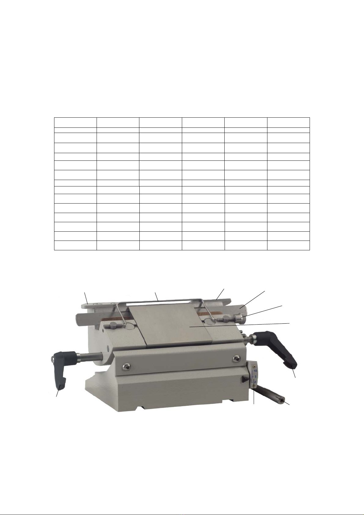
1.2.8 SPECIMEN ORIENTATION (where fitted)
To change the orientation of the specimen, first unlock the clamping lever, then either turn
the adjusting knobs, or move the specimen holder by hand.
NOTE: Before attempting to change the orientation ensure cutting hand wheel is locked.
1.2.9 ADVANCE / REWIND CONTROL
The Advance / Rewind control (on top of the microtome) is
used to advance the specimen to the knife and for trimming. It is also used to reset the
mechanism usually after cutting each specimen.
NOTE: the control cannot be rewound if the specimen is at the top of the cutting stroke;
either lower the specimen or set the thickness control to 0µm to disengage the ratchet
mechanism.
A used feed indicator on the front of the microtome shows how much of the specimen-advance
remains. Rewind the mechanism when the white pointer reaches the red zone, by turning the knob on
top of the microtome clockwise, or if Motorised Advance / Rewind is fitted then see paragraph 1.2.13
1.2.10a LEFT HAND SIDE ADVANCE/REWIND CONTROL - /LHS (where fitted)
The operation is exactly the same as for the Advance/Rewind control on the top of the microtome. Please note that this
option is not available with Motorised Advance/Rewind
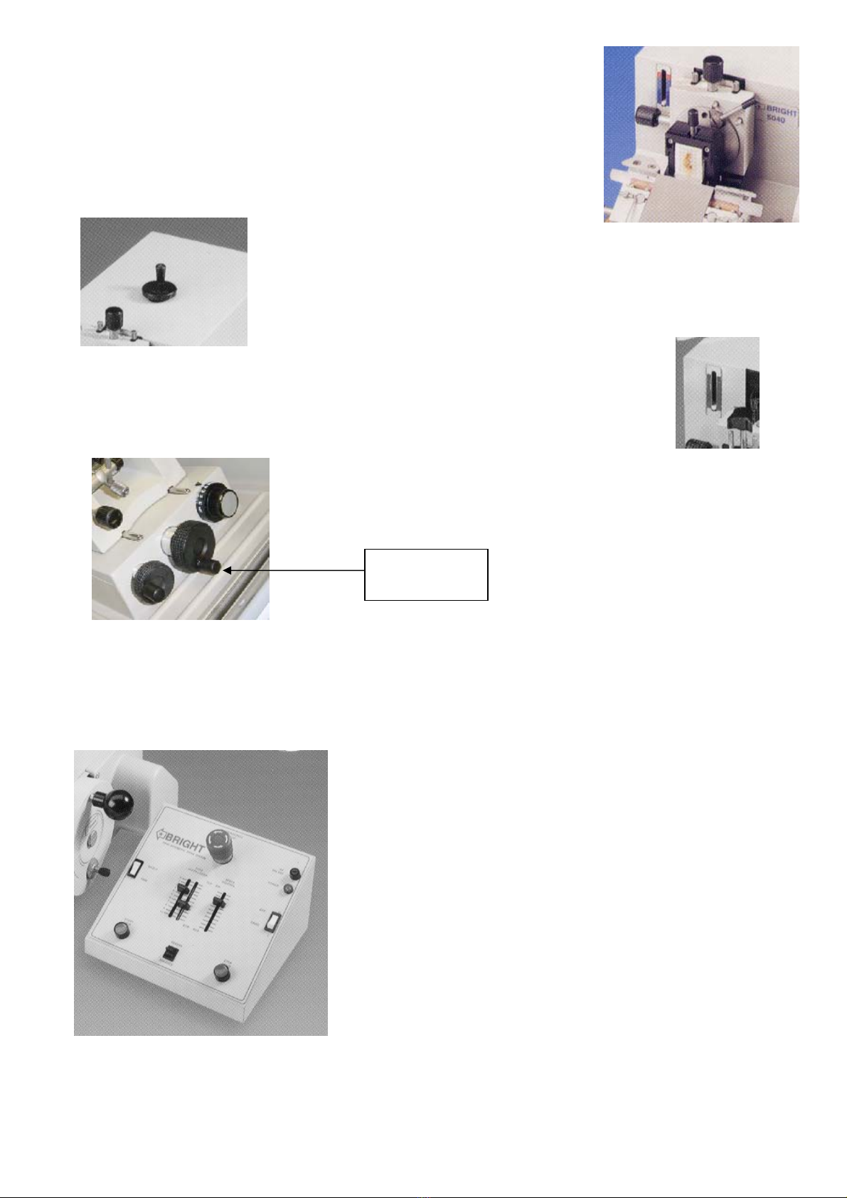
1.2.10 MOTOR DRIVE (where fitted)
The motorised cutting system on the 5040 microtome is used for cutting large or hard specimens, and is also useful for
serial sectioning. The system can be disengaged for manual cutting.
1. Ensure the specimen will not collide with the knife.
2. To engage motor drive, pull and turn hand wheel plunger knob.
Then slowly rotate hand wheel until plunger engages. The hand
wheel is locked in motor drive. See section 1.2.1 for manual use.
3. Switch on drive. The green power light will illuminate.
4. Select trim mode (for continuous running of motor drive) press
start button (green)
5. Use the speed control to adjust cutting speed, when the head is in
the cutting zone.
6. Adjust the zone control. The space between the upper and lower
positions indicates that part of the specimen travel which is
determined by the speed control.
7. By switching to single, the arm will be made to stop at the bottom
of each stroke, allowing section collection.
8. To stop the drive, press stop. Start and stop functions can be used at any time.
9. The emergency-stop button stays in when pressed. Twist button in direction of arrows to release. Then press
start to continue drive.
LHS (Cryostat
version)