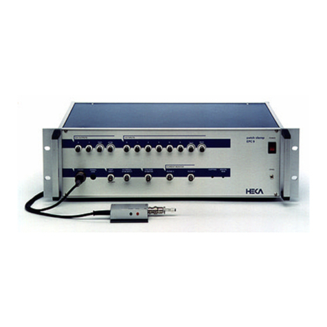
HEKA EPC 10 USB User manual

EPC 10 USB
USER MANUAL
EPC 10 USB Manual, Version 3.0

HEKA Elektronik GmbH Phone +49 7121 90925 26
Aspenhaustrasse 21 Fax +49 7121 90925 11
D-72770 Reutlingen Website www.heka.com /www.elproscan.com
Germany Email eimeaorderscmt@harvardbioscience.com
HEKA Electronic Phone +1 800 597 0580
84 October Hill Road Fax +1 508 429 5732
01746 Holliston Website www.heka.com /www.elproscan.com
EPC 10 USB • March 2022 • www.heka.com


TABLE OF CONTENTS
Table of Contents
Table of Contents iv
List of Figures vi
List of Tables vii
1 General Information 1
1.1 ImportantSafetyAdvice............................................ 1
2 Introduction 5
2.1 IntroducingtheEPC10USB.......................................... 5
2.2 References .................................................... 6
2.3 NamingConventions.............................................. 7
2.4 MSWindowsversions ............................................. 7
2.5 Macintosh .................................................... 7
3 Description of the Hardware 9
3.1 Headstage .................................................... 9
3.2 HDMIRedStarHeadstage........................................... 9
3.3 MainUnit .................................................... 10
3.3.1 Front-panel ............................................... 10
3.3.2 Rear-panel................................................ 12
3.4 EPC 10 USB DOUBLE, TRIPLE, and QUADRO . . . . . . . . . . . . . . . . . . . . . . . . . . . . . . . 12
3.5 SpecialFeaturesoftheEPC10USB...................................... 13
3.5.1 Timing of the AD-/DA-channels . . . . . . . . . . . . . . . . . . . . . . . . . . . . . . . . . . . 13
4 Installation 15
4.1 InstallingSoftwareonly ............................................ 15
4.2 Installing Hardware and Software . . . . . . . . . . . . . . . . . . . . . . . . . . . . . . . . . . . . . . 15
4.3 Conventions................................................... 15
4.4 ConnectingtheHardware ........................................... 16
4.5 Protection Key (’Dongle’) Installation . . . . . . . . . . . . . . . . . . . . . . . . . . . . . . . . . . . . 17
iEPC 10 USB • March 2022 • www.heka.com

TABLE OF CONTENTS
4.5.1 USBDongleInstallation........................................ 17
4.5.1.1 MSWindows......................................... 17
4.5.1.2 MacOS ............................................ 17
4.6 SoftwareInstallation .............................................. 17
4.6.1 MSWindows .............................................. 17
4.6.2 MacOS.................................................. 18
4.7 CalibratingtheHardware ........................................... 18
4.8 SupportHotline................................................. 19
5 Amplifier Window 21
5.1 GlobalSection.................................................. 22
5.1.1 Tweak .................................................. 23
5.1.1.1 ViewTab ........................................... 23
5.1.1.2 HardwareTab ........................................ 24
5.1.1.3 ToolsTab ........................................... 26
5.1.1.4 CompensationTab...................................... 28
5.2 AmplifierSelection ............................................... 30
5.3 AmplifierParameters.............................................. 31
6 Verifying and Testing the EPC 10 USB 37
6.1 Testing the EPC 10 USB with the Model Circuit . . . . . . . . . . . . . . . . . . . . . . . . . . . . . . . 37
6.1.1 TheModelCircuit ........................................... 37
6.1.2 "SETUP" - Applying the Test Pulse . . . . . . . . . . . . . . . . . . . . . . . . . . . . . . . . . . 38
6.1.3 "SEAL" - Voltage Clamp Recording . . . . . . . . . . . . . . . . . . . . . . . . . . . . . . . . . . 40
6.1.4 "Whole-Cell" - Voltage Clamp Recording . . . . . . . . . . . . . . . . . . . . . . . . . . . . . . 42
6.1.5 "Whole-Cell" - Current Clamp Recording . . . . . . . . . . . . . . . . . . . . . . . . . . . . . . 45
6.1.6 Measuring the Noise of the Amplifier . . . . . . . . . . . . . . . . . . . . . . . . . . . . . . . . 47
6.2 MakingaFullTest................................................ 48
7 Operating Modes 51
7.1 VoltageClampMode.............................................. 51
7.2 CurrentClampMode.............................................. 51
7.3 Low Frequency Voltage Clamp Mode . . . . . . . . . . . . . . . . . . . . . . . . . . . . . . . . . . . . 53
8 Compensation Procedures 55
8.1 SeriesResistanceCompensation........................................ 55
8.2 CapacitanceCompensation .......................................... 57
8.3 OffsetCompensation.............................................. 58
9 Patch Clamp Setup 61
EPC 10 USB • March 2022 • www.heka.com ii

TABLE OF CONTENTS
9.1 MountingtheProbe............................................... 61
9.2 GroundWires .................................................. 61
9.3 GroundingtheMicroscope........................................... 61
9.4 ExternalShielding................................................ 62
9.5 ConnectionstootherInstruments....................................... 62
9.6 PipetteHolderandElectrode ......................................... 62
9.7 BathElectrode.................................................. 63
10 Patch Pipettes 65
10.1GlassCapillaries................................................. 65
10.2Pulling ...................................................... 65
10.3Coating...................................................... 65
10.4HeatPolishing.................................................. 66
10.5UseofPipettes.................................................. 66
11 Using the Patch Clamp 67
11.1FormingaSeal.................................................. 67
11.1.1 InitialSetup............................................... 67
11.1.2 EnteringtheBath............................................ 67
11.1.3 FormingaGigaseal........................................... 67
11.2Cell-AttachedRecording............................................ 68
11.3Whole-CellRecording ............................................. 68
11.3.1 BreakingthePatch ........................................... 68
11.3.2 Capacitive Transient Cancellation . . . . . . . . . . . . . . . . . . . . . . . . . . . . . . . . . . 69
11.3.3 Series Resistance Compensation . . . . . . . . . . . . . . . . . . . . . . . . . . . . . . . . . . . 69
11.4CurrentClampRecording ........................................... 70
12 Low Noise Recording 71
13 Appendix I: Digital Inputs/Outputs 73
13.1DigitalI/OConnector ............................................. 73
13.2DigitalInConnector .............................................. 74
13.3DigitalOutConnector ............................................. 74
13.4BreakoutCables................................................. 75
13.5ConnectingCables ............................................... 76
13.5.1 DG 4/5 / Lambda 10-2 / Lambda 10-3 to EPC 10 USB . . . . . . . . . . . . . . . . . . . . . . 76
13.5.2 ValveLink8toEPC10USB ...................................... 78
14 Appendix II: Probe Adapters 79
14.1StandardMountingPlate............................................ 79
iii EPC 10 USB • March 2022 • www.heka.com

TABLE OF CONTENTS
14.2DovetailMountingPlate............................................ 79
15 Appendix III: S-Probe 81
16 Appendix IV: Pipette Holder 83
16.1BNC-Type .................................................... 83
16.2SMA-Type .................................................... 84
EPC 10 USB • March 2022 • www.heka.com iv

LIST OF FIGURES
List of Figures
2.1 EPC10USBPatchClampamplifier ..................................... 5
3.1 EPC 10 USB HDMI Red Star Headstage . . . . . . . . . . . . . . . . . . . . . . . . . . . . . . . . . . . 9
3.2 EPC10USBFrontPanel............................................ 10
3.3 EPC10USBRearPanel ............................................ 12
3.4 Double Staggered Acquisition Mode of the DAQ board. . . . . . . . . . . . . . . . . . . . . . . . . . . 13
4.1 Exemplary start dialog of the calibration process. . . . . . . . . . . . . . . . . . . . . . . . . . . . . . . 18
4.2 Prompting dialog for shielding the probe inputs. . . . . . . . . . . . . . . . . . . . . . . . . . . . . . . 19
4.3 Prompting dialog for connecting the model cell. . . . . . . . . . . . . . . . . . . . . . . . . . . . . . . 19
5.1 Default Settings of the Amplifier Window. . . . . . . . . . . . . . . . . . . . . . . . . . . . . . . . . . . 21
5.2 The three sections of the Amplifier Window. . . . . . . . . . . . . . . . . . . . . . . . . . . . . . . . . 22
5.3 Global Section of the Amplifier Window. . . . . . . . . . . . . . . . . . . . . . . . . . . . . . . . . . . . 22
5.4 Tweak extension of the Amplifier Window. . . . . . . . . . . . . . . . . . . . . . . . . . . . . . . . . . 23
5.5 ViewtaboftheAmplifierWindow....................................... 23
5.6 Hardware tab of the Amplifier Window. . . . . . . . . . . . . . . . . . . . . . . . . . . . . . . . . . . . 24
5.7 ToolstaboftheAmplifierWindow....................................... 27
5.8 Amplifier Info dialog of the Tweak menu. . . . . . . . . . . . . . . . . . . . . . . . . . . . . . . . . . . 27
5.9 Compensation tab of the Amplifier Window. . . . . . . . . . . . . . . . . . . . . . . . . . . . . . . . . 28
5.10 Amplifier Selection of an EPC 10 USB Double amplifier. . . . . . . . . . . . . . . . . . . . . . . . . . 30
5.11 Amplifier Parameters of an EPC 10 USB amplifier. . . . . . . . . . . . . . . . . . . . . . . . . . . . . 31
5.12 Bridge Compensation Options in Current Clamp Mode. . . . . . . . . . . . . . . . . . . . . . . . . . . 35
6.1 ModelCircuitoftheMC-10 .......................................... 37
6.2 EPC 10 USB Double Amplifier and Test Pulse window. . . . . . . . . . . . . . . . . . . . . . . . . . . 38
6.3 BeforeC-Fastcompensation.......................................... 40
6.4 AfterC-Fastcompensation........................................... 41
6.5 BeforeC-Slowcompensation ......................................... 42
6.6 AfterC-Slowcompensation .......................................... 43
6.7 CurrentClampMode.............................................. 45
vEPC 10 USB • March 2022 • www.heka.com

LIST OF FIGURES
6.8 Noisemeasurement............................................... 47
6.9 The Full Test is selectable in the Tools selection of the Amplifier Window. . . . . . . . . . . . . . . . . 48
7.1 Circuitry of the Voltage Clamp mode of the EPC 10 USB. . . . . . . . . . . . . . . . . . . . . . . . . . 51
7.2 Circuitry of the Current Clamp mode of the EPC 10 USB. . . . . . . . . . . . . . . . . . . . . . . . . 52
8.1 Series Resistance Compensation Circuit of the EPC 10 USB. . . . . . . . . . . . . . . . . . . . . . . . 56
9.1 Bathelectrode .................................................. 63
13.1 Digital I/O connector (40-Pin, male) of the EPC 10 USB . . . . . . . . . . . . . . . . . . . . . . . . . . 74
13.2 Digital In connector (DSub-25, female) of the EPC 10 USB . . . . . . . . . . . . . . . . . . . . . . . . . 74
13.3 Digital Out connector (DSub-25, female) of the EPC 10 USB. . . . . . . . . . . . . . . . . . . . . . . . 75
13.4 DSub-25, female, to 8x BNC breakout cable . . . . . . . . . . . . . . . . . . . . . . . . . . . . . . . . . 75
13.5 DSub-25 (male) to DSub-25 (female) connecting cable . . . . . . . . . . . . . . . . . . . . . . . . . . . 76
13.6 DSub-25 (male) to DSub-9 (male) connecting cable . . . . . . . . . . . . . . . . . . . . . . . . . . . . . 78
14.1 Standard Mounting Plate for EPC 10 USB pre-amplifiers. . . . . . . . . . . . . . . . . . . . . . . . . . 79
14.2 Dovetail Mounting Plate for EPC 10 USB pre-amplifiers. . . . . . . . . . . . . . . . . . . . . . . . . . 79
15.1 S-Probe Headstage with HDMI cable. . . . . . . . . . . . . . . . . . . . . . . . . . . . . . . . . . . . . 81
15.2 Adapter for connecting the model circuit to the S-Probe . . . . . . . . . . . . . . . . . . . . . . . . . . 81
16.1 BNC-type Pipette Holder for the Red Star Headstage . . . . . . . . . . . . . . . . . . . . . . . . . . . 83
16.2 Pipette Holder SMA-type for the S-Probe . . . . . . . . . . . . . . . . . . . . . . . . . . . . . . . . . . 84
EPC 10 USB • March 2022 • www.heka.com vi

LIST OF TABLES
List of Tables
3.1 Number of free DA/AD channels in EPC 10 USB Multi amplifiers. . . . . . . . . . . . . . . . . . . . 13
5.1 Current Gain ranges of the EPC 10 USB amplifier. . . . . . . . . . . . . . . . . . . . . . . . . . . . . . 32
5.2 Filter 1 setting according to the defined Series Resistance Compensation speed . . . . . . . . . . . . 36
8.1 Maximum RS-compensation values. . . . . . . . . . . . . . . . . . . . . . . . . . . . . . . . . . . . . . 57
8.2 Exemplary solutions and their Liquid Junction Potentials. . . . . . . . . . . . . . . . . . . . . . . . . . 59
12.1 Noise Contribution of Different Hardware Components. . . . . . . . . . . . . . . . . . . . . . . . . . 71
13.1 Pin assignment of the Digital I/O Connector (EPC 10 USB). . . . . . . . . . . . . . . . . . . . . . . . . 73
13.2 Pin assignment of the Digital In Connector (EPC 10 USB), upper row. . . . . . . . . . . . . . . . . . . 74
13.3 Pin assignment of the Digital In Connector (EPC 10 USB), lower row. . . . . . . . . . . . . . . . . . . 74
13.4 Pin assignment of the Digital Out Connector (EPC 10 USB), upper row. . . . . . . . . . . . . . . . . . 74
13.5 Pin assignment of the Digital Out Connector (EPC 10 USB), lower row. . . . . . . . . . . . . . . . . . 75
13.6 Pin assignments of Digital Out Connector of EPC 10 USB and Parallel Port connector of DG 4/5. . . 76
13.7 Pin assignments of Digital Out Connector of EPC 10 USB and Parallel Port connector of Lambda 10-2. 77
13.8 Pin assignments of Digital Out Connector of EPC 10 USB and Parallel Port connector of Lambda 10-3. 77
13.9 Pin assignments of Digital Out Connector of EPC 10 USB and connector of ValveLink 8. . . . . . . . 78
vii EPC 10 USB • March 2022 • www.heka.com


1 General Information
1.1 Important Safety Advice
Warning: Make sure to read the following advice prior to installation or use of the device and the soft-
ware. If you do not fulfill all requirements stated below, this may lead to malfunctions or breakage of
connected hardware, or even fatal injuries.
Warning: Always obey the rules of local regulations and laws. Only qualified personnel should be
allowed to perform laboratory work. Work according to good laboratory practice to obtain best results
and to minimize risks.
Warning: The device and the software are not intended for medical uses and must not be used on hu-
mans. HEKA Elektronik GmbH assumes no responsibility in any case of contravention.
The product has been built to the state of the art and in accordance with recognized safety engineering rules. The
device may only
• be used for its intended purpose;
• be used when in a perfect condition.
Improper use could lead to serious, even fatal injuries to the user or third parties and damage to the device itself
or other material damage.
Malfunctions which could impair safety should be rectified immediately.
Grounding
This product is grounded through the grounding conductor on the power cord. To avoid electric shock, the
grounding conductor must be connected to earth.
Orient the Equipment Properly
Do not orient the equipment so that it is difficult to manage the disconnection device.
High Voltage
Electrical cords must be properly laid and installed. The length and quality of the cords must be in accordance
with local provisions.
Only qualified technicians may work on the electrical system. It is essential that the accident prevention regula-
tions and those of the employers’ liability associations are observed.
Each time before starting up, make sure that the power supply agrees with the specifications of the product. Check
the power cord for damage each time the site is changed. Damaged power cords should be replaced immediately
1EPC 10 USB • March 2022 • www.heka.com

1.1. Important Safety Advice
and may never be reused. Check the leads for damage. Damaged leads should be replaced immediately and may
never be reused. Do not try to insert anything sharp or metallic into the vents or the case. Liquids may cause short
circuits or other damage. Always keep the device and the power cords dry. Do not handle it with wet hands.
EPC 10 USB • March 2022 • www.heka.com 2

1.1. Important Safety Advice
Requirements for the Installation
Make sure that the device is not exposed to direct sunlight. Do not place anything on top of the device, and do
not place it on top of another heat producing device, so that the air can circulate freely.
Explanation of the Symbols used
Caution/Warning DC (direct current)
Guarantee and Liability
The general conditions of sale and delivery of HEKA Elektronik GmbH always apply. They can be found online
at www.heka.com/sales/sales_main.html#terms.
HEKA Elektronik GmbH makes no guarantee as to the accuracy of any and all tests and data generated by the
use of the device or the software. It is up to the user to use good laboratory practice to establish the validity of his
/ her findings.
Guarantee and liability claims in the event of injury or material damage are excluded when they are the result of
one of the following:
• Improper use of the device
• Improper installation, commissioning, operation or maintenance of the device.
• Operating the device when the safety and protective devices are defective and/or inoperable.
• Non-observance of the instructions in the manual with regard to transport, storage, installation, commis-
sioning, operation or maintenance of the device.
• Unauthorized structural alterations to the device.
• Unauthorized modifications to the system settings.
• Inadequate monitoring of device components subject to wear.
• Improperly executed and unauthorized repairs.
• Unauthorized opening of the device or its components.
• Catastrophic events due to the effect of foreign bodies or acts of God.
Operator’s Obligations
The operator is obliged to allow only persons to work on the device, who
• are familiar with the safety at work and accident prevention regulations and have been instructed how to
use the device;
• are professionally qualified or have specialist knowledge and training and have received instruction in the
use of the device;
• have read and understood the chapter on safety and the warning instructions in this manual and confirmed
this with their signature.
It must be monitored at regular intervals that the operating personnel are working safely. Personnel still under-
going training may only work on the device under the supervision of an experienced person.
3EPC 10 USB • March 2022 • www.heka.com

1.1. Important Safety Advice
EPC 10 USB • March 2022 • www.heka.com 4

2 Introduction
The patch clamp technique was introduced by Neher and Sakmann (1976) for recording the currents in a small
patch of membrane under voltage clamp conditions. In the intervening years a number of changes have occurred,
most notably the development of the "gigaseal" by E. Neher (1981). Various recording configurations allow intra-
cellular recordings to be made with the same type of recording setup as used for patch recording from the cell
surface or cell-free membrane patches (Hamill et al., 1981).
2.1 Introducing the EPC 10 USB
Figure 2.1: EPC 10 USB Patch Clamp amplifier
The EPC 10 USB represents roughly the tenth in the series of patch clamp designs in use in the Göttingen lab-
oratories. It is a logical successor to the classical EPC 7, retaining all of its features but adding a number of
capabilities. Like the EPC 9, the EPC 10 USB implements full digital control of the various functions. Thus,
the digitally controlled EPC 10 USB patch clamp amplifier has no knobs, switches or dials. The acquisition soft-
ware (PATCHMASTER or PATCHMASTER NEXT) replaces the analog controls of conventional amplifiers by using
a computer and a built-in AD/DA converter. The convenient graphics display and mouse operations provide
5EPC 10 USB • March 2022 • www.heka.com

2.2. References
unsurpassed versatility and ease of operation. In addition to the controls for the amplifier and the built-in filters,
our acquisition software contains a powerful data acquisition system (sampling and storage in pulse, ramp and
continuous modes), a fully programmable Pulse Generator, a digital Oscilloscope and the Protocol Editor for
automation processes. Thus, the EPC 10 USB offers all the features of a complete workstation for controlling ex-
periments and acquiring data. Furthermore, there are several analysis software packages available, which allow
data analysis, data export, and graphics output.
The EPC 10 USB also accepts a stimulus input and provides analogue current and voltage monitor outputs just
like conventional amplifiers to operate in combination with a host computer running custom and commercial
software from other sources. The versatility of the EPC 10 USB can best be appreciated by the variety of ex-
periments that can be carried out with it. Besides high-resolution recordings of single channels, it can be used
in studies of whole-cell voltage and current clamp, exocytosis (by monitoring changes in cell membrane capac-
itance), and recordings from artificial membranes or loose-patch experiments. Technically, the EPC 10 USB is
noteworthy for three special features, the range-changing capability of the probe, the extremely wide bandwidth
available from the current monitor circuitry, and the integrated transient cancellation (automatically if desired)
and series-resistance compensation functions. In current clamp mode, the EPC 10 USB pre-amplifier acts as an
“voltage-follower”, similar to classical microelectrode amplifiers, which guarantees very fast and accurate mem-
brane potential recordings (Magistretti et al., 1996). Together, these features mean that a single probe suffices for
both single-channel and whole cell recordings, and that both kinds of recordings can be made with high time
resolution and low noise.
This manual is designed to provide a general guide for setting up and using the EPC 10 USB for experiments. It
covers general information about the hardware, basic principles of the EPC 10 USB’s functions and patch clamp
techniques. It is assumed that the reader has some familiarity with patch clamp techniques; should you be a
newcomer to the field perhaps the best place to start would be the paper by Hamill et al., where the basic gigaseal
techniques are described and the first three chapters of Single Channel Recording (B. Sakmann & E. Neher, eds.,
Plenum Press, New York, 1995). Certainly, it will be worthwhile to read this manual carefully. Many users will
want to read some of the more advanced and complete discussions of individual topics which can be found in
original articles and in the books Single Channel Recording (B. Sakmann & E. Neher, eds., Plenum Press, New
York, 1995) and Methods in Enzymology, vol. 207 (Academic Press, New York, 1992).
2.2 References
Original Articles
Hamill, O. P., Marty, A., Neher, E., Sakmann, B. & Sigworth, F. J. (1981) Improved patch clamp techniques for
high-resolution current recording from cells and cell-free membrane patches. Pflugers Arch. 391, 85-100.
Magistretti, J., Mantegazza, M., Guatteo, E. & Wanke, E. (1996) Action potentials recorded with patch-clamp
amplifiers: are they genuine? TINS 19, 530-534.
Neher, E. (1981) Unit conductance studies in biological membranes. In: Techniques in Cellular Physiology (P. F.
Baker, ed.) Elsevier/North Holland.
Neher, E. & Sakmann, B. (1976) Single-channel currents recorded from membrane of denervated frog muscle
fibres. Nature 260, 779-802.
Rae, J. & Levis, R. (1984) Patch clamp recordings from the epithelium of the lens obtained using glasses selected
for low noise and improved sealing properties. Biophys. J. 45, 144-146.
Barry, P. H. & Lynch, J. W. (1991) Liquid junction potentials and small cell effects in patch-clamp analysis. J. Memb.
Biol. 121, 101-117.
Sigworth, F. J., Affolter, H. & Neher, E. (1995) Design of the EPC-9, a computer-controlled patch-clamp amplifier.
2. Software. J. Neurosci. Methods 56, 203-221.
EPC 10 USB • March 2022 • www.heka.com 6

2.3. Naming Conventions
Peters, F., Gennerich, A., Czesnik, D. & Schild, D. (2000) Low frequency voltage clamp: recording of voltage
transients at constant average command voltage. J. Neuroscience Meth. 99, 129-135.
Gillis, K.D. (2000) Admittance-based measurements of membrane capacitance using the EPC-9 patch-clamp am-
plifier. Pflugers Arch. 439:655-664.
Book Chapters
Penner, R. (1995) Chapter 1: A practical guide to patch clamping. In: Single-Channel Recording (B. Sakmann & E.
Neher, eds.) Plenum Press, New York.
Marty, A. & Neher, E. (1995) Chapter 2: Tight-seal whole-cell recording. In: Single-Channel Recording (B. Sak-
mann & E. Neher, eds.) Plenum Press, New York.
Heinemann, S. H. (1995) Chapter 3: Guide to data acquisition and analysis. In: Single-Channel Recording (B.
Sakmann & E. Neher, eds.) Plenum Press, New York.
Sigworth, F. J. (1995) Chapter 4: Electronic design of the patch clamp. In: Single Channel-Recording (B. Sakmann
& E. Neher, eds.) Plenum Press, New York.
Neher, E. (1995) Chapter 6: Voltage offsets in patch-clamp experiments. In: Single Channel-Recording (B. Sak-
mann & E. Neher, eds.) Plenum Press, New York.
Colquhoun, D. & Sigworth, F. J. (1995) Chapter 19: Fitting and statistical analysis of single-channel records. In:
Single-Channel Recording (B. Sakmann & E. Neher, eds.) Plenum Press, New York.
Neher, E. (1992) Correction for liquid junction potentials in patch clamp experiments. In: Methods in Enzymology
207, 123-131, Academic Press, New York.
2.3 Naming Conventions
EPC 10 USB Single, EPC 10 USB Double, EPC 10 USB Triple and EPC 10 USB Quadro: Throughout the
present manual we will address all EPC 10 USB amplifier types as “EPC 10 USB”. We will explicitly mention the
particular amplifiers, where it is required.
2.4 MS Windows versions
The EPC 10 USB is supported by Windows 8 and Windows 10.
Throughout the present manual we will address all the above Windows versions as “MS Windows”. We will
explicitly mention the particular MS Windows versions, whenever it is required. A free USB 2.0 port is required.
2.5 Macintosh
The EPC 10 USB USB is supported by Macintosh computers running Mac OS X 10.6 or newer. A free USB 2.0
port is required.
7EPC 10 USB • March 2022 • www.heka.com

2.5. Macintosh
EPC 10 USB • March 2022 • www.heka.com 8

3 Description of the Hardware
The hardware components of the EPC 10 USB series patch clamp system consist of the headstage (or probe), the
amplifier main unit with an integrated AD/DA converter board. The EPC 10 USB amplifier is connected to the
computer via a USB 2.0 cable. Specific information about the hardware installation is given below in chapter 4 on
page 15.
3.1 Headstage
The EPC 10 USB can be used with different headstages. The default headstage delivered with the EPC 10 USB
is the HDMI Red Star headstage.
If you are interested in another headstage and their appropriate purpose please contact us at
eimeaorderscmt@harvardbioscience.com.
3.2 HDMI Red Star Headstage
Figure 3.1: EPC 10 USB HDMI Red Star Headstage
The probe of the EPC 10 USB is contained in a small enclosure, designed to be mounted on a micromanipulator
and directly attached to the recording micropipette. It contains the sensitive amplifier that constitutes the current-
to-voltage converter, as well as components for injecting signals into that amplifier. On the probe are the following
connectors:
Input Connector: This is a Teflon-insulated BNC connector. The standard pipette holder plugs directly into this
connector; the center pin is the amplifier input, and the shield is driven with the command potential (Vp).
Avoid touching the probe’s input terminal, since the input circuitry of the probe can be damaged
by static electricity. When it is necessary to touch the input (e.g., while inserting a pipette into the
holder), ground yourself first by touching a grounded metal surface.
GND Connector: The black pin jack carries a high quality ground signal which is useful for grounding the bath
electrode and nearby shields without potential errors that could arise from ground loops. This ground is con-
nected directly to the signal ground on the controller through the probe’s cable. More details on grounding
practices will be provided in chapter 9 on page 61.
9EPC 10 USB • March 2022 • www.heka.com
Table of contents
Other HEKA Laboratory Equipment manuals
Popular Laboratory Equipment manuals by other brands

Keysight
Keysight SL1200A Series operating instructions

Analytik Jena
Analytik Jena SPECORD 200 manual

Beckman Coulter
Beckman Coulter GH-3.8 Instructions for use

Analytic Jena
Analytic Jena InnuPure C16 operating manual

COMINOX
COMINOX SterilClave 18 VLS Use and maintenance manual

Omni
Omni TISSUE MASTER 125 user manual

Julabo
Julabo ME-4 operating manual

Fisher Scientific
Fisher Scientific Finnpipette Instructions for use

Boekel
Boekel Slide Moat 240000 operating instructions

ELITechGroup
ELITechGroup AEROSPRAY GRAM 7322 Applications manual

IKA
IKA IC control operating instructions

Millipore
Millipore Spectroquant Multy operating manual