Bras à ressort RA-SAB-15-36
Documents supplémentaires
Vous trouverez les documents suivants contenant des informations complémentaires à
la présente notice sur notre siteWeb www.turck.com:
■Fiche technique
Pour votre sécurité
Utilisation correcte
Le bras à ressort est conçu pour fixer des roues mesureuses d’une circonférence de
200…500 mm avec des codeurs rotatifs à arbre plein avec bride de serrage et un
diamètre de 58 mm.
Les appareils doivent exclusivement être utilisés conformément aux indications figurant
dans la présente notice. Toute autre utilisation est considérée comme non conforme.
La société Turck décline toute responsabilité en cas de dommages causés par une
utilisation non conforme.
Exemples de mauvaises utilisations
■Les appareils ne constituent pas des composants de sécurité et ne peuvent pas être
utilisés à des fins de protection des personnes ou des choses.
Consignes générales de sécurité
■Seul un personnel qualifié est habilité à monter, installer, utiliser et entretenir
l’appareil.
■Ne raccordez des appareils entre eux que si leurs caractéristiques techniques le
permettent.
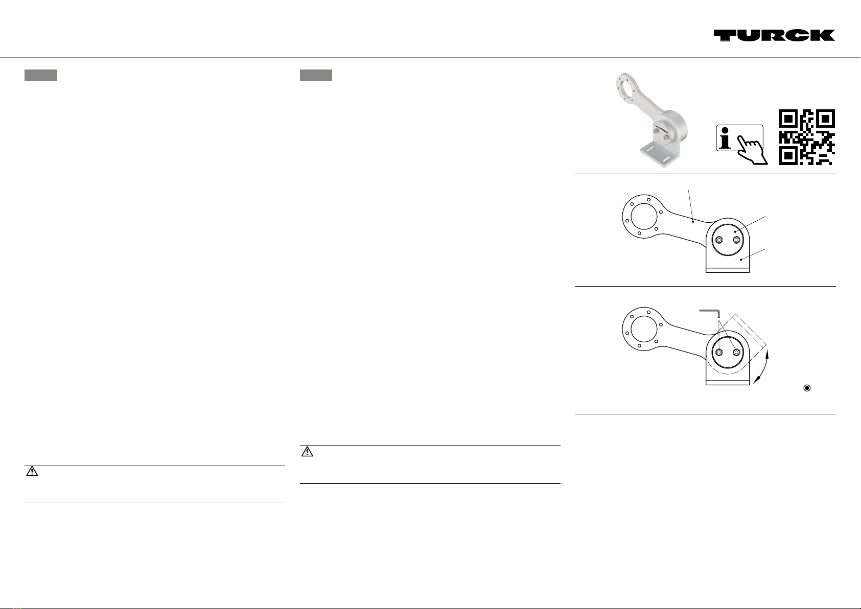
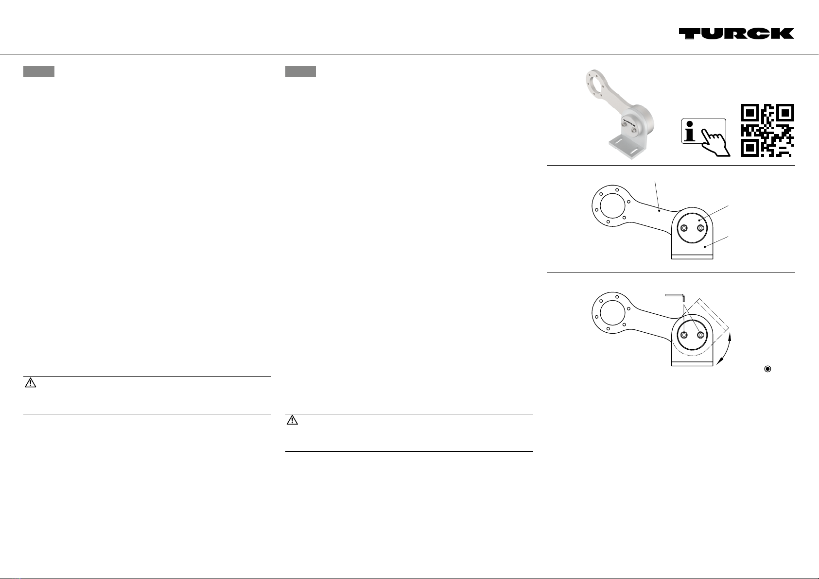
Description du produit
Aperçu de l’appareil
Voir fig.1
Le bras à ressort se compose de trois parties (voir fig.2):
■Support de montage (1)
■Bras à ressort avec unité de ressort (2)
■Capuchon de serrage (3)
Fonctions et modes de fonctionnement
Le bras à ressort est conçu pour fixer des roues mesureuses d’une circonférence de
200à500mm avec des codeurs d’un diamètre de 58mm. L’encodeur et la roue mesu-
reuse peuvent être montés à 360° à l’aide de la fixation à 6trous de chaque côté du bras
à ressort.
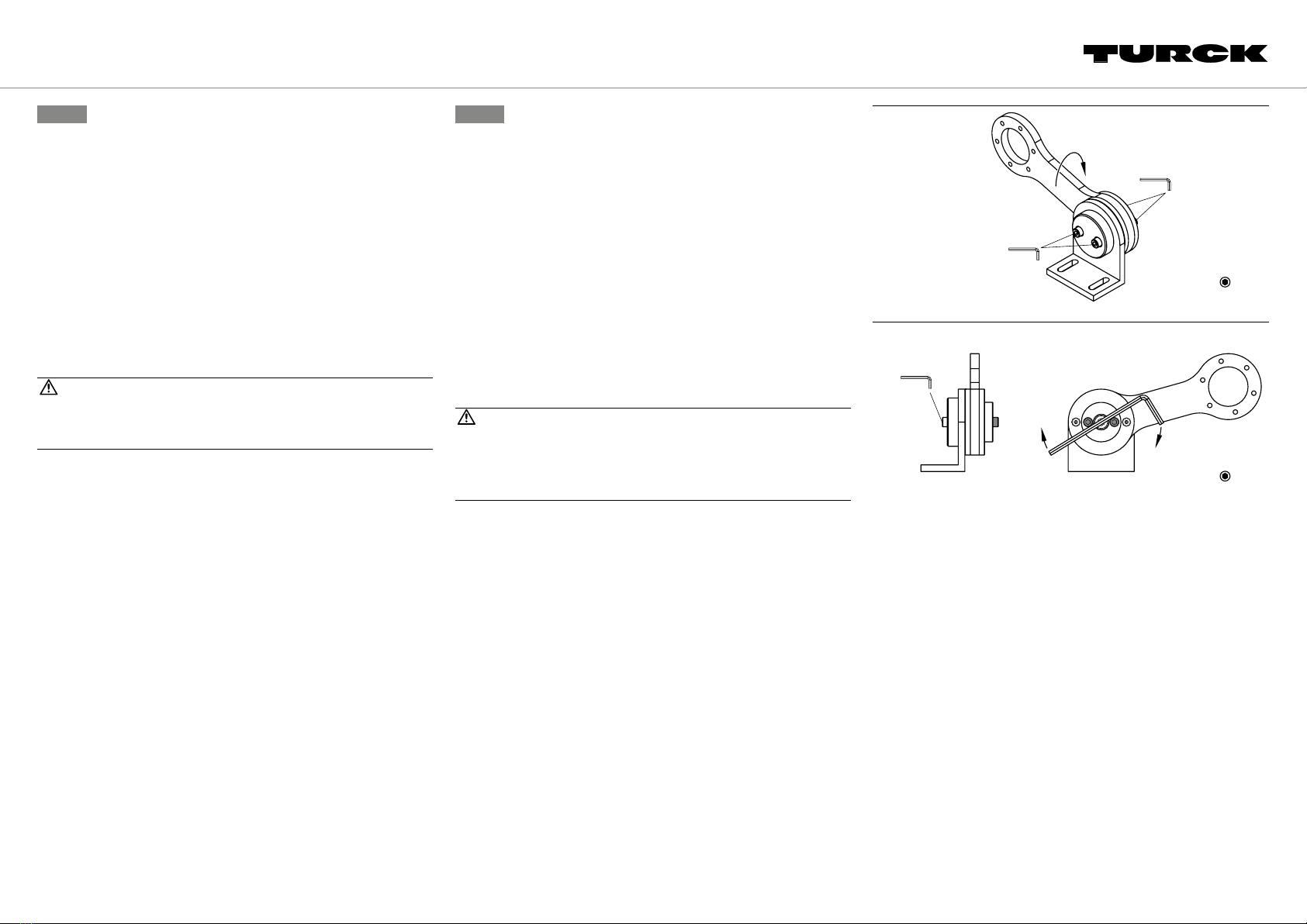
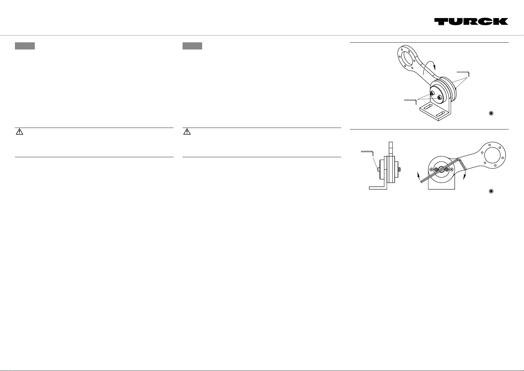
Montage
ATTENTION
Desserrage de la vis centrale
Risque de blessures liées au saut du ressort!
➤Ne desserrez pas la vis centrale.
Le bras à ressort peut être monté depuis le bas ou le haut de la distance mesurée. Le
couple de serrage maximal des vis est de 2Nm.
Réglage de la position de l’équerre de montage (voir g.3)
➤ Desserrez les deux vis cylindriques argentées.
➤ Réglez la position requise de l’équerre de montage entre 0et360°.
➤ Serrez les deux vis cylindriques argentées.
FR Guide d'utilisation rapide ES Guía de inicio rápido
Brazo accionado por resorte RA-SAB-15-36
Documentos adicionales
Además de este documento, se puede encontrar el siguiente material en la Internet en
www.turck.com:
■Hoja de datos
Para su seguridad
Uso correcto
El brazo de resorte está diseñado para fijar ruedas de medición con una circunferencia
de 200…500 mm junto con codificadores de eje macizo con una brida de sujeción y un
diámetro de 58 mm.
Los dispositivos solo se deben usar como se describe en estas instrucciones. Ninguna
otra forma de uso corresponde al uso previsto. Turck no se responsabiliza de los daños
derivados de dichos usos.
Uso indebido evidente
■Los dispositivos no son componentes de seguridad y no se deben utilizar para la
protección de personas y propiedades.
Instrucciones generales de seguridad
■Solo personal capacitado y calificado puede montar, instalar, operar y dar
mantenimiento al dispositivo.
■Solo combine los dispositivos con aquellos que son adecuados para el uso conjunto
según lo descrito en los datos técnicos.
Descripción del producto
Descripción general del dispositivo
Consulte la fig.1
El brazo accionado por resorte consta de tres secciones (consulte la fig.2):
■Soporte para montaje (1)
■Brazo accionado por resorte con unidad de resorte (2)
■Tapa de fijación (3)
Funciones y modos de operación
El brazo accionado por resorte está diseñado para fijar ruedas de medición con una
circunferencia de 200 a 500mm con codificadores de 58mm de diámetro. El codificador
y la rueda de medición pueden montarse en ambos lados del brazo accionado por
resorte y en cualquier posición alrededor de 360°.
Instalación
PRECAUCIÓN
Desatornille el tornillo central.
Evite las lesiones causadas por la liberación de los resortes.
➤No desatornille el tornillo central.
El brazo accionado por resorte se puede instalar por debajo o por encima de la sección
de medición. El par de apriete máximo de los tornillos es de 2Nm.
Ajuste la posición del soporte para montaje (consulte la g.3).
➤ Desatornille los dos tornillos cilíndricos plateados.
➤ Ajuste la posición requerida del soporte para montaje entre 0…360°.
➤ Vuelva a apretar los dos tornillos cilíndricos plateados.
© Hans Turck GmbH & Co. KG | 100038687 2022-05
RA-SAB-15-36
RA-SAB-15-36
Spring Loaded Arm
Quick Start Guide
Doc. no. 100038687
Additional
information see
1
3
2
3
4 mm
2 Nm
360°
turck.com