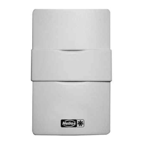
Helios AIR1/KWL-VOC 0-10V User manual

Mischgassensor zur Erfassung der Mischgas-Konzen-
tration in der Raumluft
Mixed gas sensor for measuring mixed gas concentrati-
ons in room air
Sonde de qualité d’air mixte pour détecter la concentra-
tion des composés organiques volatils dans l‘air ambi-
ant
AIR1/KWL-VOC 0-10V
Helios Ventilatoren
MONTAGE UND BETRIEBSVORSCHRIFT
INSTALLATION AND OPERATING INSTRUCTIONS
NOTICE DE MONTAGE ET D‘UTILISATION
EN
DE
FR

1
DEDE
Raumsensor AIR1/KWL-VOC 0-10V
Montage- und Betriebsvorschrift
1.1 Wichtige Informationen
Zur Sicherstellung einer einwandfreien Funktion und zur eigenen Sicherheit sind alle
nachstehenden Vorschriften genau durchzulesen und zu beachten. Nationale einschlägi-
gen Normen, Sicherheitsbestimmungen und Vorschriften (z.B. DIN EN VDE 0100) sowie
die TAB des EVUs sind unbedingt zu beachten und anzuwenden.
Die Bedienungsanleitung als Referenz am Gerät aufbewahren. Nach der Endmontage
muss dem Betreiber (Mieter/Eigentümer) das Dokument ausgehändigt werden.
1.2 Warn- und Sicherheitshinweise
Nebenstehendes Symbol ist ein sicherheitstechnischer Warnhinweis. Alle Sicher-
heitsvorschriften bzw. Symbole müssen unbedingt beachtet werden, damit jeg-
liche Gefahrensituation vermieden wird.
m GEFAHR
Warnung vor Gefahren, die bei Missachtung der Maßnahmen unmittelbar zu Tod oder
schweren Verletzungen führen.
m WARNUNG
Warnung vor Gefahren, die bei Missachtung der Maßnahmen zu Tod oder schweren Ver-
letzungen führen können.
m VORSICHT
Warnung vor Gefahren, die bei Missachtung der Maßnahmen zu Verletzungen führen können.
ACHTUNG
Warnung vor Gefahren, die bei Missachtung der Maßnahmen zu Sachschäden führen können.
1.3 Garantieansprüche – Haftungsausschluss
Wenn die nachfolgenden Ausführungen nicht beachtet werden, entfällt unsere Gewähr-
leistung. Gleiches gilt für Haftungsansprüche an den Hersteller. Der Gebrauch von Zu-
behörteilen, die nicht von Helios empfohlen oder angeboten werden, ist nicht statthaft.
Eventuell auftretende Schäden unterliegen nicht der Gewährleistung.
1.4 Vorschriften – Richtlinien
Bei ordnungsgemäßer Installation und bestimmungsgemäßem Betrieb entspricht das
Produkt den zum Zeitpunkt seiner Herstellung gültigen Vorschriften und EG-Richtlinien.
1.5 Sendungsannahme
Die Lieferung enthält den Raumsensor AIR1/KWL-VOC 0-10 V. Die Sendung ist sofort
bei Anlieferung auf Beschädigungen und Typenrichtigkeit zu prüfen. Falls Schäden vor-
liegen umgehend Schadensmeldung unter Hinzuziehung des Transportunternehmens
veranlassen. Bei nicht fristgerechter Reklamation gehen evtl. Ansprüche verloren.
1.6 Einlagerung
Bei Einlagerung über einen längeren Zeitraum sind zur Verhinderung schädlicher Ein-
wirkungen folgende Maßnahmen zu treffen:
Schutz durch trockene, luft- und staubdichte Verpackung (Kunststoffbeutel mit Trocken-
mittel und Feuchtigkeitsindikatoren). Der Lagerort muss erschütterungsfrei, wasser-
geschützt und frei von übermäßigen Temperaturschwankungen sein. Schäden, deren
Ursprung in unsachgemäßem Transport, unsachgemäßer Einlagerung oder Inbetrieb-
nahme liegen, sind nachweisbar und unterliegen nicht der Gewährleistung.
1.7 Bestimmungsgemäße Verwendung
Wartungsfreier Raumsensor AIR1/KWL-VOC 0-10V mit aktivem/schaltendem Ausgang,
automatischer Kalibrierung, im formschönen Kunststoffgehäuse mit Schnappdeckel, zur
Ermittlung der Luftqualität bzw. Luftgüte. Der Messumformer wandelt die Messgrößen in
ein Normsignal von 0 -10 V. Der Fühler findet Einsatz in Büros, Hotels, Tagungsräumen,
Wohnungen, Geschäften etc. und dient zur Bewertung des Raumklimas. Dies ermöglicht
eine energiesparende, bedarfsgerechte Raumbelüftung und somit eine Senkung der Be-
triebskosten und Steigerung des Wohlbefindens.
KAPITEL 1
ALLGEMEINE
HINWEISE
m
mGEFAHR
mWARNUNG
mVORSICHT
ACHTUNG

2
DEDE
Raumsensor AIR1/KWL-VOC 0-10V
Montage- und Betriebsvorschrift
Ein bestimmungsfremder Einsatz ist nicht zulässig!
1.8 Funktionsweise
Die Luftgüte wird mittels AIR1/KWL-VOC 0-10 V (Mischgassensor für flüchtige organi-
sche Substanzen) erfasst. Dieser ermittelt die Belastung der Raumluft durch verunrei-
nigte Gase wie Zigarettenrauch, Körperausdünstungen, Atemluft, Lösungsmitteldämpfe,
Emissionen etc. Bezüglich der zu erwartenden Luftkontamination ist eine geringe, mittle-
re oder hohe VOC-Empfindlichkeit einstellbar.
2.1 Technische Daten
AIR1/KWL-
VOC 0-10V
Maße (B x H x T) mm 85 x 85 x 27 mm
Spannungsversorgung 24 V AC ⁄ DC (± 10 %)
Leistungsaufnahme 0,6 W ⁄ 24 V DC;
1,2 VA ⁄ 24 V AC;
Peakstrom 200 mA
Sensor VOC-Sensor (Metalloxid) (volatile organic com
pounds = flüchtige organische Substanzen),
mit manueller Kalibrierung (über Zero-Taster),
mit automatischer Kalibrierung (permanent aktiv)
Messbereich VOC 0...2000 ppm, Mehrbereichsumschaltung (über
DIP-Schalter wählbar), VOC-Sensibilitäten (low/
medium/high)
Ausgang (0 V = saubere Luft, 10V = verschmutzte Luft),
0-10 V mit Offset-Potentiometer (±10% vom
Messbereich)
Relais-Ausgang mit potentialfreiem Wechsler (24 V / 1 A) (Schalt-
punkteinstellbar von 0...100% des Ausgangssig-
nals)
Messgenauigkeit ± 20 % EW (bezogen auf das Kalibriergas)
Lebensdauer > 60 Monate (unter Normalbelastung), abhängig
von Belastungsart und Gaskonzentration
Gasaustausch Diffusion
Umgebungstemperatur 0...+ 50 °C
Einlaufzeit ca. 1 Stunde
Ansprechzeit ca. 1 Minute
elektrischer Anschluss 0,14 - 1,5 mm2, über Schraubklemmen
Gehäuse Kunststoff, Werkstoff ABS, Farbe Reinweiß (ähn-
lich RAL 9010)
Montage Wandmontage oder auf UP-Dose, Ø 55 mm,
Unterteil mit 4-Loch, für Befestigung auf senk-
recht oder waagerecht installierten UP-Dosen
für Kabeleinführung hinten, mit Sollbruchstelle für
Kabeleinführung oben ⁄ unten bei AP
Schutzklasse III (nach EN 60 730)
Schutzart IP 30 (nach EN 60 529)
Normen CE-Konformität, elektromagnetische Verträglich-
keit nach EN 61 326, EMV-Richtlinie
2014 ⁄ 30 ⁄ EU, Niederspannungsrichtlinie
2014 ⁄ 35 ⁄ EU
ACHTUNG
KAPITEL 2
DATEN

3
DEDE
Raumsensor AIR1/KWL-VOC 0-10V
Montage- und Betriebsvorschrift
2.2 Maße
3.1 Gehäuse öffnen
Schnapphaken nach innen drücken (s. Abb. 2).
Beim späteren Zusammenbau die Schnapphaken auf einer Seite des Gehäuseunterteils
einhaken und das Gehäuse einrasten.
TK: ø 60
85
85
27.2
Abb. 1
KAPITEL 3
ELEKTRISCHER
ANSCHLUSS Abb. 2

4
DEDE
Raumsensor AIR1/KWL-VOC 0-10V
Montage- und Betriebsvorschrift
3.2 Elektrischer Anschluss
Bei Anschluss an ein Lüftungsgerät oder Ventilator, dessen Anschlussplan beachten,
siehe Montage- und Betriebsvorschrift des Lüftungsgeräts oder Ventilators.
Maximale Leitungslänge zwischen Sensor und Steuerung: 50 m.
Empfohlener Leitungstyp für den Sensoranschluss: Geschirmte Leitung (bauseits) mit
je 0,5 mm² Litzenquerschnitt. Der Schirm ist steuerungsseitig auf den GND aufzulegen.
1
2
3
131112
+UB 24 V AC/DC
Ausgang VOC 0 .. 10 V
-UB GND
Schließer
COM
Öffner
set of fsetzero
ON DIP
12345
85499-221 SS-1408 19.11.2020
DIP-Schalter
DIP 2 DIP 1 VOC-Sensibilität
OFF OFF Gering
OFF ON Medium (default)
ON OFF Hoch
DIP 3 VOC-Nullpunktautomatik
ON aktiviert (default)
OFF deaktiviert
D
DIP 4 Ausgang
ON nicht verwendet
OFF Spannung 0 - 10 V (default)
DIP 5 intern
ON nicht verwendet
OFF default
Abb. 3

5
DEDE
Raumsensor AIR1/KWL-VOC 0-10V
Montage- und Betriebsvorschrift
Der Gasaustausch im Sensorelement erfolgt durch Diffusion. Je nach Konzen-
trationsänderung und Strömungsgeschwindigkeit der Luft in Sensorumgebung
kann die Reaktion des Gerätes auf die Konzentrationsänderung verzögert
auftreten. Die Einbaulage des Gerätes ist zwingend so zu wählen, dass der
Sensor vom Luftstrom umspült wird. Anderenfalls kann der Gasaustausch wesentlich
verlangsamt oder verhindert werden.
4.1 Allgemeine Information zur Luftqualität
Es existiert keine weltweit einheitliche Norm, auf die sich ein VOC-Sensor (Volatile
Organic Compounds = flüchtige, organische Substanzen) beziehen könnte. Da in
der zu überwachenden Luft eine Vielzahl von Stoffen vorkommt, auf welche der
Sensor reagiert und sich Gasgemische einstellen, wirkt dieser Sensor nicht selektiv,
sondern spiegelt die allgemeine Luftqualität wieder. Auch die Aussage, was ist
„schlechte Luft“ oder was ist „gute Luft“ kann nicht prinzipiell getroffen werden, denn
dies ist eine rein subjektive Empfindung.
4.2 Automatische Kalibrierung der Luftqualität (permanent aktiv)
Wir empfehlen eine Spülung des Sensors mit frischer Luft für mindestens
20 Minuten alle 7 Tage als Basis für die automatische Kalibrierung. In einem
Zeitraum von ca. 3 Wochen wird der minimale Ausgangswert für die Luftquali-
tät gespeichert. Während dieses Intervalls wird eine Normierung des Aus-
gangssignals zum Nullpunkt vorgenommen. Die maximale Korrektur pro Inter-
vall ist hierbei begrenzt. Langzeitdriften und die betriebsbedingte Alterung des
Sensorelementes werden somit völlig eliminiert.
Der automatische Kalibrierzyklus wird bei jedem Einschalten des Gerätes neu
gestartet und ein Korrekturwert über die Betriebsdauer ermittelt. Bei
Spannungsunterbrechung kürzer 7 Tage kann der Berechnungsalgorithmus
durch eine manuelle Kalibrierung unterstützt werden, um eine schnellere An-
passung des Korrekturwertes zu erreichen.
4.3 Manuelle Kalibrierung der Luftqualität
Vor und während des Kalibriervorganges ist für ausreichend Frischluft zu
sorgen!
Wir empfehlen eine Frischluftzufuhr von mindestens zwei Stunden bevor
die manuelle Kalibrierung gestartet wird.
Der Kalibriervorgang wird durch das Drücken (ca. fünf Sekunden)
des Tasters „ZERO“ gestartet. Dies wird über die blinkende LED signalisiert.
Anschließend erfolgt die Kalibrierung. Während dieser Phase ist die LED
ständig aktiv und ein 60-Sekunden-Countdown läuft ab.
4.4 Inbetriebnahme
Nach dem Einschalten des Gerätes erfolgen ein Selbsttest und die Temperie-
rung. Dieser Vorgang dauert je nach Umgebungsbedingungen 30 - 50 Minu-
ten.
Anschließend kann optional eine manuelle Kalibrierung durchgeführt werden.
Dabei ist darauf zu achten, dass keine Schadstoffe den Kalibriervorgang be-
einflussen und der Sensor bei Frischluft betrieben wird.
4.5 Schaltpunkteinstellung
Über das Potentiometer SET kann ein Schaltpunkt zwischen 10 % und 95 %
des des Messbereichs gewählt werden. Als Schaltausgang steht ein poten-
tialfreier Wechslerkontakt zur Verfügung.
4.6 Offset
Eine nachträgliche Justage des VOC-Messwertes kann über das Offset-
Potentiometer erfolgen. Der Nachstellbereich liegt bei ± 10 % vom Messbe-
reich.
KAPITEL 4
INBETRIEB
NAHME

6
DEDE
Raumsensor AIR1/KWL-VOC 0-10V
Montage- und Betriebsvorschrift

1
ENEN
Room sensor AIR1/KWL-VOC 0-10V
Installation and operating instructions
1.1 Important information
In order to ensure complete and effective operation and for your own safety, all of the
following instructions should be read carefully and observed. The relevant national stan-
dards, safety regulations and instructions (e.g. DIN EN VDE 0100) as well as the technical
connection conditions of the energy supply company must be observed and applied.
Keep the operating instructions close to the unit for easy reference. After the final assem-
bly, the document must be issued to the operator (tenant/owner).
1.2 Warning and safety instructions
The adjacent symbol is a safety-relevant warning symbol. All safety regulations
and/or symbols must be absolutely adhered to, so that any dangerous situation
is avoided.
mDANGER
Indicates dangers which will directly result in death or serious injury if the safety instruction is
not followed.
m WARNING
Indicates dangers which will result in death or serious injury if the safety instruction is not
followed.
m CAUTION
Indicates dangers which can result in injuries if the safety instruction is not followed.
ATTENTION
Indicates dangers which can result in material damage if the safety instruction is not followed.
1.3 Warranty claims – Exclusion of liability
Our warranty shall not apply if the following instructions are not observed. The same
applies for liability claims against the manufacturer. The use of accessories, which are
not recommended or offered by Helios, is not permitted. Any damage that may occur is
not liable for warranty.
1.4 Regulations - Guidelines
If the product is installed correctly and used to its intended purpose, it conforms to all
applicable regulations and EC guidelines at its date of manufacture.
1.5 Receipt
The delivery contains the room sensor AIR1/KWL-VOC 0-10 V incl. connection cable.
Please check delivery immediately on receipt for accuracy and damage. If damaged,
please notify the carrier immediately. In case of delayed notification, any possible claim
may be void.
1.6 Storage
When storing for a prolonged time, the following steps are to be taken to avoid damaging
influences:
Protection by dry, air-dustproof packing (plastic bags with drying agent and moisture
indicators). The storage place must be waterproof, vibration-free and free of temperature
variations. Damages due to improper transportation, storage or commissioning must be
verified and are not liable for warranty.
1.7 Intended use
Maintenance-free room sensor AIR1/KWL-VOC 0-10 V with active/switching out-
put, automatic calibration in an elegant plastic housing with snap-on lid for deter-
mining the air quality. The measuring transducer converts the measured values
into a standard signal of 0 -10 V.
The sensor is used in offices, hotels, convention centres, apartments, shops, etc.
for the purpose of evaluating the indoor climate. This enables energy-saving room
ventilation on an as-needed basis, thereby reducing operating costs and improv-
ing well-being.
Any use other than the intended use is prohibited!
CHAPTER 1
GENERAL INFORMA-
TION
m
mDANGER
mWARNING
mCAUTION
ATTENTION
ATTENTION

2
ENEN
Room sensor AIR1/KWL-VOC 0-10V
Installation and operating instructions
1.8 Functionality
The air quality is detected by AIR1/KWL-VOC 0-10 V (mixed gas sensor for
volatile organic substances). This sensor determines the loading of the room
air due to contaminated gases such as cigarette smoke, body perspiration,
exhaled breathing air, solvent vapours, emissions, etc. With regard to the ex-
pected air contamination, low, medium or high VOC sensitivity can be select-
ed.
2.1 Technical data
AIR1/KWL-VOC 0-10 V
Dimensions (W x H x D) mm 85 x 85 x 27 mm
Power supply 24 V AC ⁄ DC (± 10 %)
Power consumption 0.6 W ⁄ 24 V DC;
1.2 VA ⁄ 24 V AC;
peak current 200 mA
Sensor VOC sensor (metal oxide) (VOC = volatile
organic compounds), with manual calibration
(via zero button), with automatic calibration
(permanently active)
Measuring range VOC 0...2000 ppm,
multi-range switching
(selectable
via DIP switches) VOC sensitivities
(low/medium/high)
Output (0 V = clean air, 10V = polluted air)
0 -10V with offset potentiometer (± 10 % of
the measuring range)
Relay output potential-free changeover contact (24 V /1 A)
(switchpoint can be adjusted from 0...100% of
the output signal)
Measuring accuracy ±20 % of final value (referred to calibrating
gas)
Service life > 60 months (under normal load conditions),
depending on the type of loading and gas
concentration
Gas exchange by diffusion
Ambient temperature 0...+ 50 °C
Warm up time approx. 1 hour
Response time approx 1minute
Electrical connection 0.14 - 1.5 mm2, via screw terminals
Housing plastic, material ABS, colour pure white (simi
lar to RAL 9010)
Installation wall mounting or on in-wall flusch box, Ø 55
mm, base with 4-hole for
mounting on vertically or horizontally installed
in-wall flush boxes for cable entry from the
back, with predetermined breaking point for
on-wall cable entry from top ⁄ bottom in
case of plain on-wall installation
Protection class III (according to EN 60 730)
Protection type IP 30 (according to EN 60 529)
Standards CE conformity, electromagnetic compatibili
ty according to EN 61 326, EMC Directive
2014 ⁄ 30 ⁄ EU, Low Voltage Directive
2014 ⁄ 35 ⁄ EU
CHAPTER 2
DATA

3
ENEN
Room sensor AIR1/KWL-VOC 0-10V
Installation and operating instructions
2.2 Dimensions
3.1 Open housing
Press snap-in hooks inwards (see Fig.2).
During subsequent assembly, hook in the snap-in hooks on one side of the housing
base and snap in the housing.
TK: ø 60
85
85
27.2
Fig.1
CHAPTER 3
ELECTRICAL CON-
NECTION Fig.2

4
ENEN
Room sensor AIR1/KWL-VOC 0-10V
Installation and operating instructions
3.2 Electrical connection
In case of connection to an ventilation unit or fan, observe the wiring diagram, see the
installation and operating instructions for the ventilation unit or fan.
Maximum cable length between sensor and controls: 50 m.
Recommended cable type for the sensor connection: shielded cable (provided by custo-
mer) with 0.5 mm² strand cross-section. The shield must be applied to the GND on the
control side.
1
2
3
131112
+UB 24 V AC/DC
Output air quality 0...10 V
-UB GND
set of fsetzero
ON DIP
12345
85499-221 SS-1408 19.11.2020
Normally open
contact
COM
Normally closed
contact
E
DIP switch
DIP 2 DIP 1 VOC-Sensitivity
OFF OFF Low
OFF ON Medium (default)
ON OFF High
DIP 3 VOC z ero point autom atic
ON activated (default)
OFF deactivated
DIP 4 Output
ON not us ed
OFF voltage 0 - 10 V (default)
DIP 5 internal
ON not us ed
OFF default
Fig.3

5
ENEN
Room sensor AIR1/KWL-VOC 0-10V
Installation and operating instructions
The gas inter-exchange in the sensor element happens by diffusion. Depending
on
the changes to the concentration and the flow velocity of the air surrounding
the
sensor, the reaction of the device to the change of concentration may take place
with a delay. It is essential to choose an installation location for the device in which
the air stream flows around the sensor. Otherwise the gas exchange may be con-
siderably delayed or prevented.
4.1 General information on air quality
There is no universally uniform standard, which could be applied to a
VOC sensor
(Volatile Organic Compounds). The monitored air contains a large number of sub-
stances to which the sensor responds, and gas mixtures are adjusted. Therefore
this sensor does not act selectively, but rather reflects the overall air quality. In
principle, one also cannot state precisely what is “bad air” or what is “good air”
because this is a purely subjective sensation.
4.2 Automatic air quality calibration (permanently active)
We recommend to rinse the sensor every 7 days for 20 minutes or longer with fresh
air as a basis for automatic calibration. Within a period of approx.
3 weeks, the minimum output value for air quality is saved. During this period, the
output signal is standardised to the zero point. The maximum correction per interval
is limited here. Long-term drifts and the operation-related ageing of the sensor
element are thus completely eliminated.
Every time the device is switched on, the automatic calibration cycle restarts and
calculates a correction value across the operating period. In case of power disrup-
tions of less than 7 days, the calculation algorithm may be
supported with a manual calibration to adjust the correction value more quickly.
4.3 Manual calibration of air quality
Sufficient fresh air must be provided before and after the calibration procedure!
We recommend a fresh air supply of at least two hours before starting manual
calibration.
The calibration procedure is started by pressing the “ZERO” button
(for approx. five seconds). This is signalled via the flashing LED.
Then calibration takes place. During this phase, the LED is continuously active
and a 60 second countdown runs.
4.4 Putting in operation
After switching on the device, a self-test and tempering period follows. This process
takes around 30 - 50 minutes, depending on the ambient conditions. Manual calibra-
tion can then be performed as an option. Make sure that no harmful substances
influence the calibration process and that the sensor is operated in fresh air.
4.5 Switching point setting
A switching point between 10 % and 95 % of the measuring range can be
selected using the SET potentiometer. A potential-free changeover contact is
available as a switch output.
4.6 Offset
The VOC measured value can be adjusted subsequently using the offset
potentiometer. The adjusting range is ± 10% of the measuring range.
CHAPTER 4
OPERATION

6
ENEN
Room sensor AIR1/KWL-VOC 0-10V
Installation and operating instructions

1
FRFR
Sonde d‘ambiance AIR1/KWL-VOC 0-10V
Notice de montage et d‘utilisation
1.1 Informations importantes
Il est important de bien lire et de respecter toutes les consignes suivantes pour le bon
fonctionnement du module et la sécurité des utilisateurs. Les normes et réglementations
nationales sont à respecter. Conserver la notice de montage et d’utilisation comme
référence à proximité de l’appareil. Après le montage final, le document doit être remis à
l’utilisateur (locataire / propriétaire).
1.2 Précautions et consignes de sécurité
Le symbole ci-contre indique une consigne de sécurité. Toutes les consignes et
symboles doivent être impérativement respectés afin d’éviter tout danger.
m DANGER
Dangers pouvant entrainer la mort ou des blessures graves si les mesures ne sont pas res-
pectées.
m AVERTISSEMENT
Dangers pouvant entrainer la mort ou des blessures graves si les mesures ne sont pas res-
pectées.
m ATTENTION
Dangers pouvant entrainer des blessures graves si les mesures ne sont pas respectées.
ATTENTION
Dangers pouvant entrainer des dommages matériels si les mesures ne sont pas respectées.
1.3 Garanties - Réserves constructeur
Toute demande de remplacement ou de réparation à titre gratuit sera déclinée en cas
de non-respect des indications contenues dans la notice. L’utilisation d’accessoires, non
fournis, non conseillés ou non proposés par Helios, est interdite. Si ces consignes ne
sont pas respectées, la garantie s’annule. Idem pour les réserves constructeur.
1.4 Règlementations - Normes
Cet appareil est conforme aux directives CE en vigueur le jour de sa fabrication et sous
ne réserve d’une utilisation appropriée.
1.5 Réception de la marchandise
La livraison comprend la sonde d‘ambiance AIR1/KWL-VOC 0-10 .
Dès réception, vérifier l’état et la conformité du matériel commandé. En cas d’avaries,
des réserves doivent être portées sur le bordereau du transporteur. Elles doivent être
précises, significatives, complètes et confirmées par lettre recommandée au transpor-
teur. Attention, le non-respect de ces procédures peut entraîner le rejet de la réclamation.
1.6 Stockage
Pour un stockage de longue durée et pour éviter toute détérioration préjudiciable, il
convient de se conformer aux instructions suivantes : protéger avec un emballage sec,
étanche à l’air et à la poussière (sac en matière synthétique contenant des sachets déshy-
drateurs et des indicateurs d’humidité). Stocker le matériel à l’abri de l’eau, des vibrations
et des variations de température. Les dommages dus à de mauvaises conditions de
transport ou de stockage ou à une utilisation anormale sont décelables et ne sont pas
couverts par la garantie.
1.7 Domaines d’utilisation
Sonde d’ambiance AIR1/KWL-VOC 0-10 sans entretien avec sortie active/de com-
mutation, calibrage automatique, dans un boîtier plastique
élégant avec couvercle emboîté, pour déterminer la qualité de l’air (0…100 % VOC).
Le convertisseur
de mesure convertit les grandeurs de mesure en un signal nor-
malisé de 0 -10 V.
La sonde est utilisée dans les bureaux, hôtels, salles de conférence, apparte-
ments, magasins, etc. et sert à évaluer le climat ambiant. Cela permet
d’économiser de l’énergie, d’aérer les pièces en fonction des besoins et donc de
réduire les coûts d’exploitation et d’améliorer le bien-être.
Toute autre utilisation n’est pas permise !
CHAPITRE 1
NOTES GÉNÉRALES
m
mDANGER
mAVERTISSEMENT
mATTENTION
ATTENTION
ATTENTION

2
FRFR
Sonde d‘ambiance AIR1/KWL-VOC 0-10V
Notice de montage et d‘utilisation
1.8 Fonctionnement
La qualité de l’air est déterminée à l’aide d’un
capteur COV
(capteur de gaz mixtes
pour substances organiques volatiles). Ce capteur détermine la pollution de l’air
ambiant par des gaz pollués tels que la fumée de cigarette, les odeurs corpo-
relles, l’air respirable, les vapeurs de solvants, les émissions, etc. En ce qui
concerne la contamination prévisible de l’air, une sensibilité aux COV faible,
moyenne ou élevée peut être réglée.
2.1 Données techniques
AIR1/KWL-
VOC 0-10V
Dimensions (L x H x P) mm 85 x 85 x 27 mm
Alimentation en tension 24 V ca / cc (± 10 %)
Puissance absorbée 0,6 W ⁄ 24 V cc;
1,2 VA ⁄ 24 V ca;
Pointe de courant 200 mA
Capteur capteur COV (oxide métallique) (volatile organic
compounds = composés organiques volatils),
avec étalonnage manuel (via touche zéro), avec
étalonnage automatique (actif en permanence)
Plage de mesure VOC 0 2000 ppm, commutation multi-gamme (sé
lectionnable via interrupteur DIP) sensibilités
COV (basse/moyenne/élevée)
Sortie (0 V = air propre, 10 V = air pollué)
0 -10 V avec potentiomètre offset (±10 % de la
plage de mesure)
Sortie relais avec
inverseur
sans potentiel (24 V / 1 A)
(point
de commutation réglable de 0...100% du signal
de sortie)
Précision de mesure ± 20% Vf (se référant au gaz de calibrage)
Durée de vis >60 mois (sous sollicitation normale), dépend
du type de sollicitation et de la concentration
de gaz
Échange de gaz diffusion
Température ambiante 0...+50°C
Temps de démarrage env. 1 heure
Temps de réponse env. 1 minute
Raccordement éléctrique 0,14 - 1,5 mm2, par bornes à vis
Boîtier matière plastique, matériau ABS, couleur blanc
pur (similaire à RAL 9010)
Montage montage mural ou sur boîte d‘encastrement,
Ø55 mm, partie inférieure avec 4 trous, pour
fixation sur boîtes d’encastrement montées ver-
ticalement ou horizontalement pour passage
de câble par l’arrière, avec point de rupture pour
passage de câble par le haut ⁄ bas pour montage
en saillie
Classe de protection III (selon EN 60 730)
Type de protection IP 30 (selon EN 60 529)
Normes conformité CE, compatibilité électromagnétique
selon EN 61 326, Directive « CEM »
2014 ⁄ 30 ⁄ EU, Directive basse tension
2014 ⁄ 35 ⁄ EU
CHAPITRE 2
DONNÉES

3
FRFR
Sonde d‘ambiance AIR1/KWL-VOC 0-10V
Notice de montage et d‘utilisation
2.2 Dimensions
3.1 Ouverture du caisson
Pousser les crochets d‘encliquetage vers l‘intérieur (voir. Fig.2).
Pour le remontage ultérieur, accrocher les crochets d‘encliquetage sur un côté de la
partie inférieure du boîtier et enclencher le boîtier.
TK: ø 60
85
85
27.2
Fig.1
CHAPITRE 3
RACCORDEMENT
ÉLECTRIQUE Fig.2

4
FRFR
Sonde d‘ambiance AIR1/KWL-VOC 0-10V
Notice de montage et d‘utilisation
3.2 Raccordement électrique
Lors du raccordement à un caisson ou à un ventilateur, respectez le schéma de raccor-
dement, consultez les instructions de montage et d‘utilisation du caisson ou du ventila-
teur.
Longueur maximale du câble entre la sonde et la régulation : 50 m.
Type de câble recommandé pour le raccordement de la sonde : Câble blindé (fourni par
le client) avec une section de 0,5 mm² chacun. Le blindage doit être raccordé au GND
du côté de la régulation.
1
2
3
131112
+UB 24 V AC/DC
Qualité de l'air de sortie 0...10 V
-UB GND
set of fsetzero
ON DIP
12345
85499-221 SS-1408 19.11.2020
Contact normalement
ouvert
COM
Ouvreur
F
Interrupteur DIP
DIP 2 DIP 1 Sensibilité aux VOC
OFF OFF Faible
OFF ON Medium (par défaut)
ON OFF Haut
DIP 3 Point zéro VOC automatique
ON activé (par défaut)
OFF désactivé
DIP 4 Sortie
ON non utilisé
OFF Tension 0 - 10 V (par défaut)
DIP 5 interne
ON non utilisé
OFF par défaut
Fig.3

5
FRFR
Sonde d‘ambiance AIR1/KWL-VOC 0-10V
Notice de montage et d‘utilisation
L’échange de gaz dans l’élément capteur s’effectue par diffusion. En fonction
de la variation de la concentration et de la vitesse d’écoulement de l’air dans
l’environnement du capteur, la réaction de l’appareil à la variation de la
concentration peut être retardée. Il est capital de choisir la position de
montage de l’appareil de façon à ce que le capteur soit immergé dans le débit
d’air. Si ce n’est pas le cas, il est possible que l’échange de gaz soit considé-
rablementralenti ou empêché.
4.1 Informations générales sur la qualité de l’air
Il n’existe pas de norme uniforme mondiale pouvant faire référence à un
capteur COV
(Volatile Organic Compounds = composés organiques volatils).
Étant donné que dans l’air à surveiller, de nombreuses substances sont
présentes, auxquelles le capteur réagit et que des mélanges gazeux sont
générés, le capteur n’agit pas de manière sélective, mais reflète la qualité de
l’air générale. Par ailleurs, il n’est pas possible d’affirmer dans l’absolu ce
qu’est un « air de mauvaise qualité » ou un « air de bonne qualité », car cela
relève d’une perception purement objective.
4.2 Étalonnage automatique de la qualité de l’air (actif en permanence)
Nous recommandons de nettoyer le capteur avec de l’air frais pendant au
moins 20 minutes tous les 7 jours avant le démarrage de l’étalonnage
automatique. Pendant une période d’env. 3 semaines, la valeur de départ
minimale pour la qualité de l’air est enregistrée. Pendant cet intervalle, une
mise à l’échelle du signal de sortie pour le point zéro est effectuée. La correction
maximale par intervalle est limitée. Les dérives à long terme et le vieillissement
des éléments de capteurs lié au fonctionnement sont ainsi entièrement éliminés.
Le cycle d’étalonnage automatique est redémarré à chaque mise en marche
de l’appareil et une valeur de correction est calculée pour la durée de
fonctionnement. En cas de coupure de tension inférieure à 7 jours,
l’algorithme de calcul peut être accompagné par une l’étalonnage manuel, afin
que la valeur de correction soit adaptée plus rapidement.
4.3 Étalonnage manuel de la qualité de l’air
Avant et pendant le processus d’étalonnage, assurer une alimentation
en air frais suffisante !
Nous recommandons une alimentation en air frais d’au
moins deux heures avant de lancer l’étalonnage manuel.
Le processus d’étalonnage est lancé avec une pression (env. cinq secondes)
du bouton « ZERO ». Cela est signalé par une LED clignotante.
Ensuite, l’étalonnage est effectué. Pendant cette phase, la LED est active en
continu et un compte à rebours de 60 secondes défile.
4.4 Mise en service
Après la mise en marche de l’appareil, celui-ci effectue un autocontrôle et
l’équilibrage de température. Cette opération dure 30 à 50 minutes en
fonction des conditions ambiantes.
Un calibrage manuel peut ensuite être effectué en option. S’assurer
qu’aucune substance nocive n’influence le processus d’étalonnage et que
le capteur fonctionne à l’air frais. En option, la logique ABC peut ensuite
être activée
4.5 Réglage du point de commutation
Un point de commutation entre 10 % et 95 % de la plage de mesure peut
être sélectionné via le potentiomètre SET. Un contact inverseur sans potentiel
est disponible en tant que sortie de commutation.
4.6 Offset
Un réglage ultérieur de la valeur de mesure du COV peut être effectué via le
potentiomètre offset. La plage de réglage ultérieur est de ± 10 % de la plage
de mesure.
CHAPITRE 4
MISE EN SERICE

6
FRFR
Sonde d‘ambiance AIR1/KWL-VOC 0-10V
Notice de montage et d‘utilisation

Als Referenz am Gerät griffbereit aufbewahren! Druckschrift-Nr.
Please keep this manual for reference with the unit! Print-No.
Conservez cette notice à proximité de l'appareil! No. Réf. 25 422-001/20-0328/V01/0221
Service und Information
DHELIOS Ventilatoren GmbH + Co KG · Lupfenstraße 8 · 78056 VS-Schwenningen F HELIOS Ventilateurs · Le Carré des Aviateurs · 157 av. Charles Floquet ·
CH HELIOS Ventilatoren AG · Tannstrasse 4 · 8112 Otelfingen 93155 Le Blanc Mesnil Cedex
AHELIOS Ventilatoren · Postfach 854 · Siemensstraße 15 · 6023 Innsbruck GB HELIOS Ventilation Systems Ltd. · 5 Crown Gate · Wyncolls Road ·
Severalls Industrial Park · Colchester · Essex · CO4 9HZ
www.heliosventilatoren.de
Table of contents
Languages:
Other Helios Accessories manuals

Helios
Helios KWL-KDF User manual
Helios
Helios KWL-CO2 User manual

Helios
Helios KWL-CO2 User manual
Helios
Helios KWL-FTF User manual
Helios
Helios AIR1-CO2 K User manual
Helios
Helios KWL-CO2 User manual
Helios
Helios LTA 40 User manual

Helios
Helios KWL-VOC User manual
Helios
Helios AIR1-CAP User manual

Helios
Helios AIR1/KWL-CO2 0-10V User manual
